Nigerian Journal of Technology (NIJOTECH) Vol. 35, No. 2, April 2016, pp. 398 – 403 Copyright© Faculty of Engineering, University of Nigeria, Nsukka,
Print ISSN: 0331-8443, Electronic ISSN: 2467-8821 www.nijotech.com
http://dx.doi.org/10.4314/njt.v35i2.22
OPTIMAL LOCATION OF DISTRIBUTED GENERATION ON THE NIGERIAN POWER SYSTEM J. N. Nweke1,*, A. O. Ekwue2 and E. C. Ejiogu3 1 DEPT. OF ELECTRICAL ENGINEERING
TECHNOLOGY, FEDERAL POLYTECHNIC, KAURA NAMODA, ZAMFARA STATE. NIGERIA INC./BRUNEL UNIVERSITY LONDON, LONDON, UNITED KINGDOM 3 DEPARTMENT OF ELECTRICAL ENGINEERING, UNIVERSITY OF NIGERIA, NSUKKA, ENUGU STATE. NIGERIA E-mail addresses: 1
[email protected], 2
[email protected], 3
[email protected] 2 JACOBS ENGINEERING
ABSTRACT
The optimal sizing and location of distributed generators (DG) remain crucial factors in their application for active power loss minimization as well as voltage profile improvement. This paper describes an analytical method for the optimal sizing and placement of DG in the Nigerian power network for active power loss minimization. The effectiveness of the proposed method showed a 6.2% reduction in active power losses on the 33kV Nigerian network (i.e. from 92.7MW to 87.0MW). The results showed an improvement in the voltage profile of that six load buses whose voltages were outside the statutory limit of 0.95 pu≤ Vi ≤ 1.05pu. Keywords: distributed generation; optimal placement of DG; active power loss minimisation and voltage profile improvement. 1. INTRODUCTION It has been stated in [1] that Distributed Generators (DG) are generators that are connected to the distribution network. They have the ability to reduce or postpone the need for investment in the transmission and distribution infrastructure when optimally located; the ability to reduce technical losses within the distribution networks as well as general improvement in power quality and system reliability. The Nigerian power network suffers from poor quality power supply, voltage instability, high transmission and distribution losses and low reliability [2-3]. Distributed generators (DGs) are not centrally planned or dispatched. They are usually connected to the distribution network and are usually sized between 50 to 100MW. The two parameters that have high impact on the integration of DG plants in the network are the selection of the size (rated capacity) as well as their location [4]. Some of the technical issues associated with the integration of DGs to distribution networks include frequency violations, waveform purity, ability to rapidly isolate fault equipment from the rest of the systems and ability to withstand abnormal operating conditions [5].
*Corresponding author Tel: +234-806-742-0582
This paper describes an analytical method for the optimal sizing and placement of DG in the Nigerian power network for system active power loss minimization. Section 2 provides a brief literature review of the subject whereas Section 3 describes the mathematical formulation of the algorithm being put forward. The results of simulations carried out on the 28-bus Nigerian power network are explained in Section 4 with the conclusions and areas of future research in Section 5. 2. LITERATURE REVIEW A brief review of previous work in this area will be presented in this Section to put this paper in context; an in-depth comprehensive review will not be covered due to space restrictions. Acharya, et al [6] calculated the optimal size and location of the DG to minimize active power loss based on an exact loss formula. This method was found to be most applicable for single DG unit placement when only active power is supplied by that DG. Also loss sensitivity factors were employed to select the candidate locations for Single DG placement to reduce the number of busbars considered in the search space. Kim et al [7] presented an approach based on
OPTIMAL LOCATION OF DISTRIBUTED GENERATION ON THE NIGERIAN POWER SYSTEM
Hereford ranch algorithm to optimally allocate DGs in a typical meshed network. The algorithm put forward was used to optimally allocate DGs to achieve maximum benefits by minimizing active power losses in the network. The results were compared with those based on conventional second order and genetic algorithm (GA) techniques. The work of Kim, et al [7] is considered more superior than that of Acharya, et al [6]. A genetic algorithm (GA) based optimal size and placement of DG in distribution network was proposed [8] by Singh et al. Like previous techniques, the GA method was used to find the optimal size and bus location for placing DG using power loss minimization in a network system based on bus admittance, generation information and load distribution of the system. The effectiveness of the proposed method was tested on 16, 37 and 75-bus systems. A differential evolution optimization approach was proposed by Abbagana, et al [9] to find the optimal location and size of DG units. The DG resources were embedded in the network to mainly reduce power losses and improve the voltage profile of the system as in previous developments. However, the optimization technique used a single DG sizing and placement for real power loss minimization but did not take into consideration multiple DG injection. More recently, Ram Singh, et al [10] on optimal placement of DG in radial distribution network for minimization of losses applied exact loss formula in the analytical expression to calculate optimum size and site for DG placement under the objective of system power loss reduction. It is computationally demanding and this involves using the exact loss formula based expression to calculate the optimal size of the DG at various buses and approximate total losses with the DG at different location to identify the best location. An algorithm based on bus-injection to branch- current (BIBC) and branch – current to bus voltage (BCBV) matrices is used to solve the load flow problem for radial distribution network. The proposal is computationally demanding and this may lead to error in the best DG location and sizing for system power loss minimization. 3. MATHEMATICAL FORMULATION The active power loss in the network is given by “exact loss” formula [11] as:
J. N. Nweke, et al
∑ ∑[
(
) (
)]
where
cos(
)
si (
)
Vi δi is the complex voltage at the i-th bus, rij is the resistance of the line bus i and bus j, whereas Vi and Vj are voltage at bus i and bus j . Pi and Pj are the active power injection at i-th and j-th bus respectively, Qi and Qj are the reactive power at ith bus and j-th bus respectively, N is the number of buses. To obtain the maximum power injected at a bus, i, so as to achieve minimum active power loss, we differentiate equation (1) with respect to Pi and set that to zero. ∑(
)
0
This implies that: ∑ ( 1
[
)
∑ (
0
)]
where Pi is the active power injection at node i and is the difference between active power generation and real power demand at that node. 5 PDG is the active power injected from DG placed at the node i and PD is the load demand at that node. Combining equations (4) and (5) gives equation (6)which satisfies the actual optimal size of the DG to achieve minimum active power loss. 1
[
∑ (
)]
These equations are subject to the satisfaction of the following constraints: ∑ [
cos(
)
i (
)
0 1. Load flow equations: ∑ [
i ( os (
Nigerian Journal of Technology
1
) )
0
Vol. 35, No. 2, April 2016
399
OPTIMAL LOCATION OF DISTRIBUTED GENERATION ON THE NIGERIAN POWER SYSTEM
2. Voltage constraints: Voltage constraints (in pu) at each bus ( 5% of rated voltage ) must be ≤ ≤ 9 3. The right-of- way buses (i.e. the buses which are not appropriate for DG allocation due to some restricting considerations should be excluded). 4. DG Capacity: The capacity of each DG unit should be different around its nominal value, so that each DG unit must be maintained with acceptable limit. The DG capacity is given as: ≤ ≤ 10 ≤ ≤ 11 Where and are minimum and maximum real power generation from DG capacity in kW whereas and are minimum and maximum reactive power generation from DG capacity in kVar. The flow chart of the algorithmic development is shown in Figure 1 below. The
J. N. Nweke, et al
summary of the above process considers the following steps: I. Input the load, generator and line data. II. Run Newton Raphson load flow (without DG) and calculate the total real power losses. III. Without the slack bus, find the different sizes of DGs at each bus using equation (6). IV. Place the DG at the corresponding position with optimum size and calculate real power losses using equation (1). V. Add the injection from DG for that bus and use base case values for state variables. VI. Check for constraints violation after placement of DG. VII. Locate the bus at which the active power loss is minimum or else return to step III above. VIII. Run the final Newton – Raphson load flow and find the real power total system loss. IX. End the process.
Figure 1: Flow chart for sizing and placement of DG using the proposed method Nigerian Journal of Technology
Vol. 35, No. 2, April 2016
400
OPTIMAL LOCATION OF DISTRIBUTED GENERATION ON THE NIGERIAN POWER SYSTEM
J. N. Nweke, et al
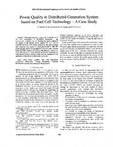
330/33KV, 50MVA transformer. This level of load is taken because major industries are connected at this line which involves complex losses. It will not give good result if the sub-system is a stand-alone case study. This is illustrated below in Figure 2 where jebba bus 330 KV line is transformed through 330/33KV, 50MVA . The total system losses cannot be optimally minimized without considering the transmission buses even though the DGs are practically placed at the distribution level. The Nigerian Power Network is made up of 5523.8km of 330kV transmission lines and thirty two (32) 330/132kV substations with total installed transformation capacity of 7,688 MVA (equivalent to 6,534.8 MW at 0.85 power factor). The Average Available Capacity on 330/132kV is 7,364MVA which is about 95.8% of installed capacity [12]. The load and transmission line data of the 28-bus Nigerian grid network were obtained from Jokojeje et al in [13]. The Nigerian 330kV transmission network was modelled in PSS/E (Power System Software for Engineering) environment as shown in Figure 3. The installed generating capacity is 7,461MW mainly hydro resources and thermal.
Figure 2: One line diagram of 330KV line to 33KV primary distribution line.
4. CASE STUDY The paper aims at optimal placement of distributed generation (DG) on the Nigerian power system for active power loss minimization. The research used the Nigerian grid network as case study on the account that the loading point where major losses are registered share with the transmission level of system network apart from the installed step-down Kano
Kaduna Gombe
Shiroro GS Jos
B/Kebbi
Mambilla Abuja
Makurdi
Kainji G/S Jebba G Ajaokuta Jebba Benin Oshogbo
Sapele GS
Ayede
Onitsha Ikeja-West
Delta GS
Aladja
New-heaven
Akangba
Papalanto GS
Aladja
Aja Egbim GS Papalanto
Figure 3: Nigeria Electric power Network modelled in PSS/E Nigerian Journal of Technology
Vol. 35, No. 2, April 2016
401
OPTIMAL LOCATION OF DISTRIBUTED GENERATION ON THE NIGERIAN POWER SYSTEM
TOTALSYSTEM ACTIVE POWER LOSS WITH AND WITHOUT DG 100 90
Total system active power loss (MW)
After running the base case Newton Raphson load flow in PSS/E environment according to the first procedure above, the result showed that buses 9 (Ayede), 13 (New Heaven), 14 (Onitsha), 16 (Gombe), 19 (Jos) and 22 (Kano) fell outside voltage statutory limit of 0.95pu ≤ Vi ≤ 1.05 pu. The total system active power loss without DG is 92.7MW. The results of the base case load flow providing the active power losses with and without DG are shown in Figure 4.
80 70 60 50 40 30 20 10 0
LOAD BUS LOSSES WITH AND WITHOUT DG With DG Without DG
Voltage profile with DG
1.2
20
1
Voltage Values (PU)
Losses (MW)
With DG
1.4
25
15
10
5
0.8
0.6
0.4
0
2
4
6
8
10 12 Load buses
14
16
18
0.2
20
Figure 4: Total Power Active Losses for all buses without/with DG The sizes of various DGs according to equation (6) using the base case state variables are shown in Figure 5. Also, the system total active power loss at various load buses is shown in Figure 6 whereas the reduction in losses from 92.7 MW to 87 MW is shown in Figure 7. OPTIMUM SIZE OF DG AT ALL THE LOAD BUSES 8 7
0
0
5
10
15 Bus numbers
20
25
30
Figure 8: Total System Voltage profile after DG placement 1
0.95
0.9
Voltage (pu)
0
Without DG
Figure 7: Total system active losses with and without DG
35
30
J. N. Nweke, et al
0.85
0.8
DG Sizes (MW)
6 5
0.75
4 3
0.7
2
0
2
4
6
8
10 12 Load buses
14
16
18
10
15 Bus number
20
25
30
20
Figure 5: Optimal Size of DG TOTAL SYSTEM ACTIVELOSSES FOR THE LOAD BUSES 12
10
8
Losses (MW)
5
Figure 9: Voltage profile without DG
1 0
0
Optimum location of DG corresponding to least loss
6
4
2
0
0
2
4
6
8
10 12 Load buses
14
16
18
20
Figure 6: Total Active Power Losses at all load buses at optimum size. Nigerian Journal of Technology
At bus 17(Abuja) load bus whose size of the DG (0.18MW) corresponds to least active power loss as shown in Figure 6. This is the most optimal position for DG location because this is the place of location of DG corresponding to least active total system power loss. Figure 4 compares the system bus losses before and after application of DG units. The result of the application of optimal size of DG at optimal site was improvement in the active power losses of the system from 92.7MW to 87.0MW as shown in Figure 7. This infers a percentage reduction of 6.2% of active power loss from the network. Also, after running the first base case Newton Raphson load flow in PSS/E Vol. 35, No. 2, April 2016
402
OPTIMAL LOCATION OF DISTRIBUTED GENERATION ON THE NIGERIAN POWER SYSTEM
environment according to the first procedure as stated above, the result showed that buses 9 (Ayede), 13 (New heaven), 14 (Onitsha), 16 (Gombe), 19 (Jos) and 22 Ka o fall outside voltage statutory limit of 0.95 ≤ Vi ≤ 1.05 pu in Figure 9. There is an improved voltages profile of the system buses to normal voltage statutory limits as shown in Figure 10. 5. CONCLUSIONS This paper has shown that, using the Nigerian power system network, the optimal sizing and location of DGs remain crucial factors in the application of DG for system active power loss minimization as well as voltage profile improvement respectively. In this study the base case load flow simulation using PSS/E was carried out and analytical method applied to determine the optimal location and sizing of DGs. The installation of DG unit at non optimal places can result in an increase in system losses which adds to the costs, resulting to low or over voltage in the network contrary to the desired objectives. But by proper siting and sizing of DG at optimal places real power loss is reduced and bus voltage gets improved in the corresponding buses respectively. Future research will address the use of GAs to reduce the computational requirements of this technique described in this paper. 6. ACKNOWLEDGEMENTS The authors are grateful to Siemens Power Technologies Inc. USA for the use of their PSS/E software to carry out the simulations described in this paper. The views expressed in this paper are those of the authors and do not represent those of Jacobs Engineering Inc. or Brunel University, London. 7. REFERENCES [1]
[2]
[3]
Ekwue A O and Akintunde O A, “The Impact of Distributed e eratio o Distributio Networks”, Nigerian Journal of Technology, Vol. 34, no. 4, April 2015, pp 325-331. Nebo C. a d Kuchi H., “Federal Mi istry of Power presentation at the Ministerial Platform for the period of May 2011 to May 2013 and Presented on July 23rd 01 ”, Retrieved from fmi.gov.ng/wpcontent/uploads/2013/07/Power.pdf Nnaji, .,“Power Sector Outlook in Nigeria: Government Renewed Priorities”, Ju e 011 http://www.sec.gov.ng/files/Prof%20Nnaji%20Pre sentation.pdf, accessed on 14th April 2014
Nigerian Journal of Technology
[4]
J. N. Nweke, et al
edighizadehM a d RezazadehA,“Usi g e etic Algorithm for Distributed Generation Allocation to Reduce losses a d Improve Voltage Profile”, World
Academy of Science, Engineering and Technology vol.37, April 2008, pp 55-58. [5]
Ekwue A. O., Nanka-Bruce O., Rao J. and McCool D., “Dy amic tability I vestigatio s of the Fault Ride Through Capabilities of a Wind Farm” Paper ID 99,
Proceedings of the 16th Power Systems Computation Conference, 14 -18 July 2008, Glasgow [6]
Acharya N, Mahat P a d Mithula a tha N, “A Analytical Approach for DG Allocation in Primary Distributio Network”, International Journal of Power and Energy Systems, vol.28, 2006 pp 669678
[7]
Kim J O, Nam W, Park K a d i gh , “Dispersed Generation Planning Using Hereford Rank Algorithm”, Electric Power System Research, Vol. 47, no. 1, Oct.1998, pp 47 – 55.
[8]
i gh D, i gh D a d Verma K , “ A ased Optimal Sizing and Placement of Distributed Generation for Loss Mi imizatio ”, Proceedings of Word Academy of Sciences, Engineering and Technology, vol.26, no.4, December 2007, pp 381– 387.
[9]
Abbagana M, Bakare A a d I. Mustapha I, “Optimal Placement and Sizing of Distributed Generator in a Power Distribution System Using Differential Evolutio ”, International Journal of Research in Engineering, vol.2, no 4, April 2012, pp 26 – 42.
[10] Ram Singh, Gursewalk Singh Brar and Navdeep Kaur, “Optimal Placeme t of D i Radial Distributio Network for Mi imizatio of Losses”,
International Journal of Advanced Research in Electrical, Electronics and Instrumentation Engineering, vol.1, no.2, Aug.2012. pp 84- 90. [11] Abdelaziz A Y, Mekhamer S F, Mohammed F M and adr M A L, “A New I tellige t Optimizatio Technique for Distribution Systems Reco figuratio ”, Proceedings of the Twelfth
International Middle-East Power Systems o fere ce MEP ON’ 00 , South Valley University, Egypt, , March 2008, pp. 397-401. [12] adiq A A, NwohuM N a d Ambifi J , “A Comparative Study on Implementation of Genetic Algorithm (GA) and ATC to Generator Siting in Nigeria 0kV Power Network”, International Journal of Engineering Sciences, vol. 2, no. 8, August 2013, pp 350- 360. [13] Jokojeje R A, Adejumobi I A, Mustapha A O and Adebisi O I, “Applicatio of tatic y chro ous Compensator (STATCOM) in Improving Power System Performance, A Case Study of the Nigeria 0kV Electricity rid”, Nigerian Journal of Technology, vol.34, no. 3, July 2015, pp 564 – 572.
Vol. 35, No. 2, April 2016
403