Feb 21, 2018 - node, in [8]â[10], the authors have proposed two multi-user scheduling schemes and analyzed the system performances for the two-way full-duplex (FD) relay ... In this case, the potentials of the good links could not be fully .... Since we have considered a practical system, the buffer at the relay node has to ...
Optimal Multi-User Scheduling of Buffer-Aided Relay Systems Pihe Hu, Cheng Li, Dingjie Xu, Bin Xia
arXiv:1802.07793v1 [cs.IT] 21 Feb 2018
Department of Electronic Engineering, Shanghai Jiao Tong University, Shanghai, China Emails: {hupihe, lichengg, xudingjie1993, bxia}@sjtu.edu.cn
Abstract Multi-User scheduling is a challenging problem under the relaying scenarios. Traditional schemes, which are based on the instantaneous signal-to-interference-plus-noises ratios (SINRs), cannot solve the inherent disparities of the qualities between different links. Hence, the system performance is always limited by the weaker links. In this paper, from the whole system throughput view, we propose an optimal multi-user scheduling scheme for the multi-user full-duplex (FD) buffer aided relay systems. We first formulate the throughput maximization problem. Then, according to the characteristics of the Karush-Kuhn-Tucker conditions, we obtain the optimal decision functions and the optimal weighted factors of different links of the proposed scheme. Simulation results show that the proposed scheme not only solves the disparities of the qualities between Si -R and R-Di links, but also that between different Si -R or Di -R links, which can be used as guidance in the design of the practical systems.
I. I NTRODUCTION Relaying communication, which is an efficient way to improve the quality of service of wireless communication systems, has been investigated extensively. Practical field tests under the long term evolution (LTE) systems have shown that the relay nodes can eliminate the coverage holes of the macro base stations [1], as well as enhance the outdoor to indoor signal strengths [2]. However, most of the existing works about the relaying communication only considered the single user scenarios [3], [4], i.e., a source node communicate with a destination node via a relay. However, in the design of the fifth generation (5G) wireless communication systems, the This work was supported in part by the the Huawei HIRP Project under Grant YB2015040062, the National Nature Science Foundation of China under Grants 61771307, 61531009 and 61521062.
February 23, 2018
DRAFT
1
volume of users is envisioned to improve 100 times compared to that of LTE systems [5], [6]. Hence, it is urgent to investigate the multi-user relay systems. In the multi-user systems, the user scheduling schemes are crucial to the system performances. For this topic, in [7], the authors proposed the Max-link selection scheme and analyzed the average achievable rate with the consideration of the independent and identically distributed (i.i.d.) fading channels. To model the distance disparities between different users to the relay node, in [8]–[10], the authors have proposed two multi-user scheduling schemes and analyzed the system performances for the two-way full-duplex (FD) relay systems under the independent but not identically distributed (i.ni.d.) fading environment. However, the results revealed that the system performances were limited by the worse one of the S-R and R-D links of the selected users. In this case, the potentials of the good links could not be fully exploited. In addition, these works did not consider the buffer at the relay node [11], which led to the fixed transmission mode, i.e., the source transmission phase was always followed by the relay transmission phase. Thereafter, the buffer was considered in the multi-user relay systems [12], [13]. However, the multiple access channels were considered rather than the multi-user scheduling schemes. In [14], the authors have proposed a multi-user scheduling scheme for the buffer aided multi-user relay system, in which the relay node could achieve the adaptive link selection. In [15], the authors have investigated the system performance of three different multi-user scheduling schemes, i.e., Max-Min, Max-Max and Max link selection schemes, for the multi-relay systems. However, even equipped with buffers, the disparities of the qualities of different links have not been solved. As a consequence, the system performance was always restricted by the weaker links. From the existing works about the multi-user relay systems, we observe that how to solve the disparities between different links remains unsolved. In this paper, we are dedicated to design an optimal multi-user scheduling scheme from the system throughput view for the FD multi-user relay systems. To solve this problem, we first formulate the throughput maximization problem as a binary integer optimization problem, which is known as an NP-hard problem. By relaxing the binary variables, we obtain the Karush-Kuhn-Tucker (KKT) optimal conditions, based on which, we further obtain the optimal decision functions and optimal weighted factors of different links. To verify the proposed scheme, numerical simulations are conducted. The results indicate that the proposed scheme not only solve the disparities between the Si -R and R-Di links, but also that between different Si -R(Di -R) links. In addition, the superiorities of the proposed scheme over the traditional schemes are revealed.
February 23, 2018
DRAFT
2
II. S YSTEM M ODEL In this section, we elaborate on the physical-layer channel mode, specific CSI requirements and basic transmission scheme, respectively. hRR
S1 Si
D1
. . .
data
. . .
R
Di
DN
SN B1 Data i
Si
Data j
Dj
...
. . .
BN
Fig. 1. The multi-user buffer aided relay system, where the source Si sends messages to Di via the relay node. The relay node is equipped with N buffers from B1 to BN . The messages from the source Si are temporarily stored in the buffer Bi , where i ∈ {1, ..., N }.
A. Channel Model As shown in the Fig.1, we consider a multi-user buffer aided FD relay system. The multiple users are pre-paired, i.e., Si exclusively sends messages to Di . We assume that the direct link between Si and Di does not exist due to the strong fading caused by the large separation, penetration loss of buildings and strong shadowing effects. The relay node R has the capability to work in the FD mode and is equipped with a large buffer, which is divided into N sub-buffers from B1 to BN . The bit messages from the source Si are first stored in the buffer Bi , and then forwarded to the destination Di in the subsequential time slots. We denote the channel coefficients of the Si -R link and R-Di link in the t-th time slot as h1i (t) and h2i (t), respectively. We assume that h1i (t) and h2i (t) are subject to the i.ni.d., stationary and ergodic stochastic distributions. In addition, we consider the block fading channels, i.e., the channel coefficients keep constant within one time slot but change independently between
February 23, 2018
DRAFT
3
different time slots. We denote the transmit powers of the sources and the relay as Ps and Pr , respectively. Hence, the instantaneous signal-to-noise-ratios (SNRs) of the Si -R and R-Di links in the t-th time slot are given by si (t) , γs g1i (t) and ri (t) , γr g2i (t), with probability density functions (pdfs) fsi (s) and fri (r), respectively. Here, g1i (t) = |h1i (t)|2 and g2i (t) = |h2i (t)|2 denote the channel gains of the Si -R and R-Di links, respectively. γs = Ps /σr2 and γr = Pr /σd2 denote the variances of the transmit SNRs of the source Si and the relay R, respectively. σr2 and σd2 denote variances the Gaussian noises at the relay node and the destination nodes, respectively. In addition, we denote the average SNRs as Ωsi , E{si (t)} and Ωri , E{ri (t)}. At this point, we can give the capacity expressions of the Si -R and R-Di links as Csi (t) = log2 (1 + si (t)), Cri (t) = log2 (1 + ri (t)).
(1)
B. CSI Requirements To perform the optimal multi-user scheduling scheme, the knowledge of the global CSI is needed at the relay node. The global CSI can be obtained by the following steps. First, at the beginning of each time slot, all the source nodes transmit the pilot signals to the relay node R, and R estimates h1i (t). Second, the relay node broadcasts the pilot signals to all the destinations, and each destination estimates h2i (t). Finally, all the destination nodes feed back the quantized version of h2i (t) to the relay node. In addition, according to the system parameters, including Ps , Pr , σr2 and σd2 , the relay node can obtain the instantaneous channel capacities of all the links. C. Basic Transmission Scheme In the traditional multi-user relay systems with or without buffers, there are two scheduling schemes. First, for the system without buffer, in each time slot the relay node has to select one pair of users simultaneously. For instance, S1 is selected to send messages and D1 is selected to receive messages in the same time slot. Second, for the system with buffer, in each time slot, the relay node always chooses the source node with maximum Csi (t) and the destination node with maximum Cri (t). However, in this paper, we abandon these two schemes and propose an optimal user scheduling scheme. In the proposed scheme, the source node and the destination node are selected independently according to the selection criteria, which will be elaborated on in the Section III. Next, we briefly explain the basic transmission scheme.
February 23, 2018
DRAFT
4
If the source node Si is selected to send messages in the t-th time slot, it transmits with the instantaneous rate Rsi (t) = Csi (t).
(2)
The messages will be first stored in the buffer Bi . We use Qi (t) to denote the buffer state, which will change to Qi (t) = Qi (t − 1) + Rsi (t).
(3)
If the destination node Di is selected to receive message in the t-th time slot, the relay node transmits with the instantaneous rate Rri (t) = min{Qi (t − 1), Cri (t)}.
(4)
The messages stored in the buffer Bi will be sent to the destination Di and the buffer state will change to Qi (t) = Qi (t − 1) − Rri (t).
(5)
III. O PTIMAL U SER S CHEDULING S CHEME In this section, we will first formulate the throughput maximization problem and then propose the optimal user scheduling scheme. A. Problem Formulation In this paper, we are dedicated to design an optimal user scheduling scheme for the buffer aided relay system under the i.ni.d. fading environment. Before that, we use the binary variables pi (t) and qi (t) to denote the indicator of which Si and Di are selected in the t-th time slot. We have the following definition: Definition 1. For the source nodes pi (t) =
1, the node Si is selected
(6)
1, the node Di is selected
(7)
0, otherwise
For the destination nodes qi (t) =
0, otherwise
February 23, 2018
DRAFT
5
It is clear that N X
pi (t) = 1,
N X
qi (t) = 1,
i=1
(8)
i=1
which guarantees that only one source node and one destination node are selected simultaneously in each time slot. In addition, we assume that all the source nodes have enough backlogged messages to transmit. Thus the average transmission rate of the source Si is given by T 1X pi (t)Rsi (t), Rsi = lim T →∞ T t=0
(9)
and the maximum average reception rate at the destination node Di is given by T 1X qi (t)Rri (t), Rri = lim T →∞ T t=0
(10)
The system throughput can be explained as the sum of the average reception rates of all the destination nodes. It is given by T =
N X i=1
N T 1 XX Rri = lim qi (t)Rri (t). T →∞ T i=1 t=0
(11)
Since we have considered a practical system, the buffer at the relay node has to satisfy the stationary conditions, which is given by Lemma 1. For a stationary buffer aided relay system, the average arrival rate and the departure rate have to satisfy Rsi ≤ Rri , i ∈ {1, ..., N}
(12)
Proof. In order to be stationary, the length of the queue in the buffer cannot increase infinitely. However, according to the queueing theory, if Rsi > Rri , the length of the queue will approach to infinity. Hence, we have Lemma 1. In addition to the stationary condition, in order to maximize the system throughput, we have the following lemma Lemma 2. To maximize the throughput, the buffer at the relay node have to be at the edge of non-absorbing state, i.e., Rsi = Rri , i ∈ {1, ..., N}
February 23, 2018
(13)
DRAFT
6
Proof. If the buffer is at the non-absorbing state, i.e., Rsi < Rri , the system throughput is limited by Rsi . Intuitively, we have two methods to improve the system throughput. One is that we can choose Si in more time slots to increase Rsi . The other is that we can choose other node except Di in more time slots to decrease Rri . Once Rsi = Rri , Rsi cannot be increased further more according to the Lemma 1. With this lemma, we can observe that the minimal limitation in (4) can be neglected. Because according to the queuing theory, when the average arrival rate equals to the average departure rate, the average queue length can be large enough. This means the relay node always have enough messages stored in the buffer, which can also be explained as that over the infinite time horizon, there are only accountable time slots that the buffer has insufficient messages to transmit. Hence, we can simplify the system throughput as N T 1 XX qi (t)Cri (t), T = lim T →∞ T i=1 t=0
(14)
Now, we are ready to present the throughput maximization problem P1 max
T
s.t. C1 :
Rsi = Rri ,
pi (t),qi (t)
C2 :
(15) ∀i
N X
pi (t) = 1,
∀t
N X
qi (t) = 1,
∀t
i=1
C3 :
i=1
C4 :
pi (t) ∈ {0, 1},
∀ i, t
C5 :
qi (t) ∈ {0, 1},
∀ i, t
(16)
where C1 ensures that every sub-buffer is at the edge of non-absorbing state. C2 and C3 guarantee that only one source and one destination node are selected during one time slot. C4 and C5 ensure that there are only two states of a source node and a destination node, i.e., selected or not selected. We note that the original problem P1 is a binary integer programming problem, which is NP-hard. To solve this problem, we relax the binary decision variables pi (t) and qi (t) to be continuous ones varying between 0 and 1, i.e., pi (t), qi (t) ∈ [0, 1]. The problem after relaxation is denoted by P2 , February 23, 2018
DRAFT
7
T
max
pi (t),qi (t)
(17)
s.t. C1 : Rsi = Rri , C2 :
∀i
N X
pi (t) = 1,
∀t
N X
qi (t) = 1,
∀t
i=1
C3 :
i=1
C4 : 1 − pi (t) ≥ 0,
∀i, t
C5 : pi (t) ≥ 0, C6 : 1 − qi (t) ≥ 0,
∀i, t ∀i, t
C7 : qi (t) ≥ 0,
∀i, t
(18)
B. Optimal Multi-User Scheduling Scheme Here we present the optimal multi-user scheduling scheme. Theorem 1. The optimal multi-user scheduling scheme maximizing the system throughput is given by For the source nodes: pk (t) = For the destination nodes: qk (t) =
1,
k = arg max Γi (t)
0,
otherwise
1,
k = arg max Λi (t)
0,
i=1,··· ,N
i=1,··· ,N
(19)
(20)
otherwise
where the optimal decision functions are given by Γi (t) = −λi F (si (t))
(21)
Λi (t) = (1 + λi )F (ri (t))
(22)
F (x) = log2 (1 + x)
(23)
in which
February 23, 2018
DRAFT
8
denotes the optimal metric function and λi ∈ (−1, 0) denotes the weighted factors of the link Si − R, which satisfy E{pi (t)Csi (t)} = E{qi (t)Cri (t)}
(24)
Proof. Please see Appendix A. Remark 1. We note that after relaxation, the original problem converts to a 2N-dimensional linear programming problem over an infinite time horizon. For this problem, the optimal solution always locates at the boundary of the feasible set, i.e., pi (t), qi (t) = 0 or 1, which coincides with the original problem. Hence, the optimal solution of the problem P2 is also the optimal solution of the original problem. Remark 2. It is noted that this scheme is particularly suitable for the i.ni.d. fading environment. Unlike the traditional multi-user scheduling scheme, in which the system performance is limited by the worse one of the S-R and R-D links, the proposed scheme can balance the quality of the Si -R and R-Di links by introducing the weighted factor λi . For instance, we assume that the expectation of the channel gain of the first pair are Ωs1 = 10 and Ωr1 = 1. We may set λ1 = −0.1 and 1 + λ1 = 0.9, which is equivalent to that the S-R link is weakened with factor 0.1 but the R-D link is weakened with factor 0.9. The source node S1 will be selected in less time slots and the destination node D1 will be selected in more time slots. By this way, the average arrival rate and the average departure rate of the buffer B1 can be balanced. IV. M AXIMUM S YSTEM T HROUGHPUT To obtain the maximum system throughput, we need to first obtain the λi , which is given by the following corollary Corollary 1. For the proposed optimal scheduling scheme in theorem 1, the optimal weighted factors are the solutions of the following equations Z His Z ∞h Y N i j fsj (sj )dt log2 (1 + si )fsi (si )dsi 0
=
Z
j=1,j6=i
∞ 0
0
Z N h Y j=1,j6=i
0
Hirj
i
(25)
λi F (si )) λj
(26)
frj (rj )drj log2 (1 + ri )fri (ri )dri
where Hsi j = F −1(
February 23, 2018
DRAFT
9
Hri j = F −1(
1 + λi F (ri )) 1 + λj
(27)
Proof. Please see Appendix B. We can obtain the optimal weighted factor λi using the built-in functions of the software packages such as Matlab or Mathmetica. Then the system throughput is given by the following Theorem. Theorem 2. Based on the theorem 1 and the corollary 1, the system throughput can be easily obtained as T =
N Z X i=1
0
∞h
N Z Y
j=1,j6=i 0
Hirj
i
frj (rj )drj log2 (1 + ri )fri (ri )dri
(28)
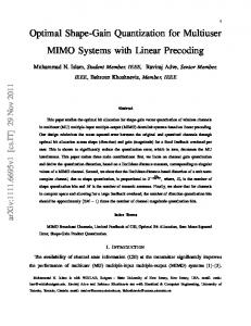
Proof. The system throughput can be easily obtained using the Total Probability Theorem, the details of the proof are omitted here. V. S IMULATION R ESULTS In this section, we present the simulation results to verify the proposed multi-user scheduling scheme. For simplicity and without loss of generality, we consider two pairs of users in the system. In the simulation, we adopt the Rayleigh fading environment with SNR expectations E{si (t)} = Ωsi , E{ri (t)} = Ωri , i ∈ {1, 2}. In addition, we also present the sub-optimal method, in which we use F ′ (x) = x to approximate F (x) = log2 (1 + x) to reduce the complexity in the simulation. As a results, the sub-optimal weighted factors will be obtained. In the Fig. 2, we plot the optimal and sub-optimal weighted factors λi versus the channel variation. We set Ωs2 = 4, Ωr2 = 6 and Ωs1 + Ωr1 = 10, and change the ratio of Ωs1 /Ωr1 . The simulation results verify that the value of λi varies between -1 and 0. In addition, we note that with the increase of the ratio Ωs1 /Ωr1 , λ1 increases from -1 to 0. Actually, this is consistent with our intuition, the larger λ1 represents that the S1 will be selected in less time slots. Furthermore, the variation of Ωs1 /Ωr1 will also affects the value of λ2 . When Ωs1 /Ωr1 is very large, λ2 will approach to -1, which implies that when S1 is selected in less time slots, then S2 will be selected in more time slots. This insight reveals the advantages of our proposed multi-user scheduling scheme. By multiplying different weighted factors, we can adjust the selection probabilities of different nodes, and by this way, to balance the disparities of the channel qualities between different Si -R links.
February 23, 2018
DRAFT
10
0
Weighted factors λi
−0.2 Opt λ1 Opt λ2 Subopt λ1
−0.4
Subopt λ2 −0.6
−0.8
−1 0
0.5
1
1.5
2
2.5
lg(Ωs1 /Ωr1 )
Fig. 2. System throughput vs. channel variation.
0
Weighted factor λi
−0.2 Opt λ1 Opt λ2 Subopt λ1 Subopt λ2
−0.4
−0.6
−0.8
−1 −2
−1.5
−1
−0.5
0
0.5
1
1.5
2
lg(Ωs1 /Ωs2 )
Fig. 3. system throughput T vs. channel variation.
Fig. 3 plots the optimal and sub-optimal weighted factor λi with the variation of the ratio Ωs1 /Ωs2 . We set Ωr1 = 4, Ωr2 = 6 and Ωs1 + Ωs2 = 10. This figure shows the relationship between the variation of the weighted factor λ1 and λ2 . The results reveals that in the low Ωs1 /Ωs2 regime, i.e., the S1 -R link is weaker than the S2 -R link, λ1 is close to -1, but λ2 is close to 0. This will lead to that S1 will be selected in more time slots than S2 . This insights reveals another advantage of the proposed scheme, i.e., the ability to balance the disparities of the channel qualities between Si -R and Sj -R, i 6= j. In addition, we note that when Ωs1 /Ωs2 ≈ 2/3, i.e., Ωs1 = 4 and Ωs2 = 6, λ1 and λ2 almost have the same value and the curves are almost completely vertical, which means any value of λ1 = λ2 is optimal. In this case, Si -R and R-Di
February 23, 2018
DRAFT
11
links have the same quality. The proposed scheme will convert to the traditional Max-Max user scheduling scheme.
0.75 0.7
System Throughput T
0.65 0.6 0.55 0.5 0.45 0.4
Pro_Opt_Sel Pro_Subopt_Sel Tra_Max−Max_Sel
0.35 0.3 0.25 −2
−1.5
−1
−0.5
0
0.5
1
1.5
2
lg(ΩS1 /ΩS2 )
Fig. 4. system throughput T vs. channel variation.
Fig. 4 plots the system throughput versus the variation of the ratio Ωs1 /Ωs2 . The figure shows that the proposed user scheduling scheme achieves considerable performance gain over the traditional Max-Max user scheduling scheme. The reason is that under the traditional Max-Max scheme, the system has no ability to balance the disparities of the qualities between different links. Hence, the throughput of each user pair is limited by the weaker one of the Si -R and R-Di links. However, the proposed scheme can schedule more time slots to the weaker links and less time slots to the stronger links. In this way, the system throughput can be improved. In addition, we note that when Ωs1 /Ωs2 ≈ 2/3, i.e., Ωs1 = 4 and Ωs2 = 6, the three different schemes have the same system throughput. This is consistent with the results in the Fig. 3. In this case, the proposed scheme converts to the traditional Max-Max scheme, which leads to the same performance. VI. C ONCLUSION In this paper, we proposed an optimal multi-user scheduling scheme for the FD multi-user buffer aided relay system. The proposed scheme could solve the disparities of the qualities between different links and maximize the system throughput. To obtain this scheme, we formulated the throughput maximization problem as an binary integer optimization problem. By relaxing the binary variables and based on the KKT optimal conditions, we obtained the optimal decision
February 23, 2018
DRAFT
12
functions and optimal weighted factors of different links. Simulations were conducted and the results verified the effectiveness and advantages of the proposed scheme over the traditional schemes. A PPENDIX A P ROOF
OF
T HEOREM 1
We note that the problem P2 is a 2N-dimensional linear programming problem over infinite time horizon. For this problem, the optimal solution satisfies the KKT optimal conditions. Hence, the lagrangian function can be expressed as L(pi (t), qi (t), λi , α(t), β(t), µi(t), νi (t), ζi (t), ηi (t)) N T 1 XX qi (t)Cri (t) = T i=1 t=0
−
T � 1 X � λi pi (t)Csi (t) − qi (t)Cri (t) N t=0
N N X X � � � � − α(t) 1 − pi (t) − β(t) 1 − qi (t) i=1
i=1
+ µi (t)[1 − pi (t)] + νi (t)pi (t) + ζi (t)[1 − qi (t)] + ηi (t)qi (t)
(29)
where λi , α(t), β(t), µi (t), νi (t), ζi (t) and ηi (t) are the Lagrange multipliers. Differentiate the L(·) function with regard to pi (t) and qi (t), and set them to zero, i.e., ∂L ∂L = 0, = 0, ∂pi (t) ∂qi (t)
(30)
we get 1 Cs (t) + α(t) − µi (t) + νi (t) = 0, N i 1 (1 + λi ) Cri (t) + β(t) − ζi (t) + ηi (t) = 0, N − λi
(31)
respectively. If we let pk (t) = 1, we obtain that νk (t) = 0, µi (t) = 0, i 6= k, according to the complementary slackness theorem. Substituting them into (31), we have N[−α(t) + µk (t)] = −λk Csk (t) , Γk (t) N[−α(t) − νi (t)] = −λi Csi (t) , Γi (t), i 6= k February 23, 2018
(32)
DRAFT
13
Since µk (t) ≥ 0, νi (t) ≥ 0, we have Γk (t) ≥ Γi (t), i 6= k, where Γi (t) denotes the optimal decision function for the source nodes. Here, we can conclude that if pk (t) = 1, Γk (t) ≥ max{Γi (t)}. Hitherto, we obtain the optimal scheduling scheme for the source nodes. In the similar way, if we set qk (t) = 1, we have N[−β(t) + ζk (t)] = (1 + λk )Crk (t) = Λk N[−β(t) − ηi (t)] = (1 + λi )Cri (t) = Λi
(33)
where ζk (t) ≥ 0, ηi (t) ≥ 0, we have Λk (t) ≥ Λi (t), i 6= k, which denotes the optimal decision function for the destination nodes. Hitherto, we have the necessary conditions of the optimal scheduling scheme for the destination nodes. Next, we need to specify the range of the optimal weighted factors λi . First, in order to make the buffers at the edge of non-absorb state, the average arrival rate should equal to the average departure rate, we have E{pi (t)Csi (t)} = E{qi (t)Cri (t)}.
(34)
Second, if λi = 0 and (1 + λi ) = 0, the corresponding source node Si and Di will never be selected. Hence, we have λi ∈ / {−1, 0}. Finally, we consider a special case, i.e., i.i.d. fading environment, which means all the links have the same link quality, i.e., completely symmetric. In this case, λ1 = λ2 = · · · = λN = c0 , where c0 is a constant. In order to maximize the system throughput, the source with the maximum Csi (t), say Sk1 and the destination with maximum Crj (t), say Dk2 will be selected. Thus, we have that −λk1 > 0 and −(1 + λk2 ) > 0. Hence, we can conclude that λi ∈ (−1, 0). A PPENDIX B P ROOF
OF
C OROLLARY 1
First, we define 2N-dimensional random variables, s(t) = {s1 (t), s2 (t), · · · , sN (t)} and r(t) = {r1 (t), r2 (t), · · · , rN (t)}, of which the pdfs are fs (s) =
N Y
fsi (si ),
(35)
N Y
fri (ri ).
(36)
i=1
fr (r) =
i=1
February 23, 2018
DRAFT
14
Hence, for i = 1, 2, · · · , N, we have Z
E{pi (t)Csi (t)} =
fs (s) log2 (1 + si )ds
−λj F (sj )