IIr,.jI
"
Journal of Intelligent and Robotic Systems 33: 187-207, 2002. © 2002 Kluwer Academic Publishers. Printed in the Netherlands.
187
Optimal Robot Speed Trajectory by Minimization of the Actuator Motor Electromechanical Losses ELEFTHERlA S. SERGAKI and GEORGE S. STAVRAKAKIS Electronic & Computer Engineering Dept., Technical University of Crete, 73100 Rania, Greece
ANASTASIOS D. POULIEZOS* Production and Management Engineering Dept., Technical University of Crete, 73100 Rania, Greece; e-mail:
[email protected] (Received: 28 July 2000; in final form: 13 February 200 1) Abstract. Tills paper considers the control problem of a robotic manipulator with separately excited dc motor drives as actuators. An innovative method is proposed willch achieves robot speed-control requirements, with simultaneous minimization of total electromechanical losses, while the drives fol low the desired speed profiles of the robot joints under various loads and random load disturbances. If there is no demand for a specific speed profile, the optimal speed trajectory is determined by minimiz ing an electromechanical losses criterion. Controllable energy losses, suc h as armature copper losses, armature iron losses, field copper losses, stray load losses, brush load losses, friction and windage losses, can be expressed proportionally to the squares of the armature and the field (exciting) currents, the angular velocity and the magnetic field flu x. The controllable energy loss term is also included in the optimal control integral quadratic performance index, defined for the whole operation period. Thus the appropriate control signals required for following the desired trajectory by simultaneous energy loss minimization for the whole operation interval are achieved. Two case studies of optimal robot control with and without minimization of actuator energy losses are presented and compared, showing the energy savings that can be achieved by the proposed methodology. Key words: industtial robots, electric actuators, dc motor actuators, direct drive rotary actuators, robotic manipulators, electromechanical losses, loss minimi zation, optimal speed trajectory.
Nomenclature, type symbols, abbreviations and robot de motor drive parameters i, w, etc.
small letters: instantaneous values
J, Q, etc.
capital letters: normalized values
f
function
io, wo, etc. ia ie
zero subscript: nominal values exciting current
Ua
armature voltage
armature current
* Corresponding author.
188
ELEFTHERIA s. SERGAKl ET AL.
Ue
stator (field) voltage
Ra
rotor resistance
La
rotor inductance
Re
field resistance
Le
field inductance
iV, -'6.2%
30o/~ notnin~1
Load
for a 3K\lV de motor
1.4.---------.----------.----------.---------.----------. 1 .2
0 .8 0 .6
~
(
0.4 0.2 0.8 time
s
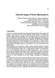
Figure 2a. The optimal excitation of a robot dc motor actuator as derived by the proposed control scheme "Test1" (Minimal effort control, with Electromechanical losses minimization, . with simultaneous Speed control, while it is following a desired speed profile under a 30% nominal load).
as many local mlruma as possible. To compare the implemented speed control approaches the reference speed was Q = 1300 rpm, generating a rectangular waveform. For the three dc motor drives used the speed response (Figure 1) showed no overshoot and it has approximated closely the reference value. Figure 2(a) shows the optimal excitation of a 3 kW dc motor actuator with min imal control effort and simultaneous minimisation of its electromechanical losses while it is following a desired speed profile of 1300 rpm (control scheme "Test1"), under a 30% nominal load. Figure 2(b) shows the optimal excitation of the same 3 kW dc drive without minimization of its electromechanical losses, which is the control scheme "Test2". In Figures 2(a), 2(b) it is noticed that the speed response excitation (Q) tends slowly to its optimum after steady state has been reached. An energy saving of 6.2%, compared with "Test2", is observed for the whole operation period. Moreover, smooth excitation signals without fluctuations and peaks are provided, which are very important in practical implementations . Figures 3, 4 and
ELEFTHERIA S. SERGAKl ET AL.
201
.",JECTORY tor a 3k:\.Al cic motor
3 0 ':'4 nominal Load
r
f.'
0 .8
1.0
~J
by the proposed control scheme "Test I" __110 es minimization). -
L oad
0 .2
for a 3KV\l' de motor
0.4
0.8
0.6
time
~
,
s
The optimal excitation of a robot dc motor actuator as derived by the control '''Ie- '" ('vlinimal effort control, without minimization of Electromechanical losses, :~.:i1e us Speed control, while it is following a desired speed profile under a 30% . : .. d) .
'0·2000 rpm
-~- 1500
rpm -.-1000 rpm
-+-500 rpm
nopt=optimal efficiency n= efficiency vy'ithout energy rninimization
:'. 6
0.8 time
s;
---
5 ,
o
r actuator as derived by tbe proposed .ih Electromechanical losses minimization, . ing a desired speed profile under a 30%
_ _ 'lKI 1
o
*' -0 2
0 .4 load (%)
~' ''-Ire
the implemented speed control = ~ 3.00 rpm, generating a rectangular .:: 2 :h peed response (Figure 1) showed : e reference value. kW dc motor actuator with min ,~: i n of its electromechanical losses ~ ~ 300 rpm (control scheme "Test! "), the optimal excitation of the same ': ~ _ tromechanical losses, which is the - I is noticed that the speed response -:zf -teady state has been reached. An - ~", i:; observed for the whole operation .\ ilhout fluctuations and peaks are __1 implementations. Figures 3, 4 and
-· 0 . -"
-:
e
- -_.
::+..
0 .5 0.6 0 .7 ior a 1 h,"VV dc motor
0.8
0 .9
Experimental study for a 1 kW robot dc motor drive: 2%- 8% efficiency im ~.. the proposed control scheme 'Testl " compared with the control scheme
- .r -'0 of the optimal efficiency that is achieved by the proposed control c - - .:"~ ' l " ompared with the control scheme "Test2", for the 1 kW, 3 kW '.\ :n' e respectively. The resulted improvement is up to 2% for heavy c( for jjght loads.
getEnrrmra -on of the Optimal Speed Trajectory ' - mlat ion an 1 kW robot dc motor drive is used. The optimization prob
l\'ed using the proposed control scheme "Test1", described previ
,__, ' l' ing different displacement times T, it was found that the optimum speed
202
ELEFTHERIA S. SERGAKl ET AL.
'---'\""'---'--o--2-0-0-0-rp-m--'~- 1-5-0-0-rp-m---){~-1-0-0-0-rp-r-n---+-'5-0-0-r-pm-----,
45 40
\
\
30 co
nopt=optimal efficiency "
35
25
li
g 20 15
n= efficiency without energy minimization
\~ -~
10
.-~----
5
--....0'-'--_'-;::1-'--r-, (:J-~~
O~~~~~~~~~~--~--~~ o
0.1
0.2 0.3 load (%) for a 3KvV dc motor
0.4
0.5
Figure 4. Experimental sUldy for a 3 kW robot dc motor drive: 2%-8% efficiency im provement by the proposed control scheme "Test!" compared with the control scheme "Test2".
7~--.---._--._--,---._--.---._--~--,
constant speed: 2000 rpm
2 1 L-_~~-~~-~~-~~--~--~--'C~====~====~ 0 .1 0.2 0 .3 0 .4 0.5 0 .6 0 .7 0 .8 0.9 load (~/o) for a GOKVV dc motor
Figure 5. Experimental study for a 60 kW robot dc motor drive: 2%-8% efficiency im provement by the proposed control scheme 'Test!" compared with the control sc heme 'Test2".
profile depended on k = Tn", / T . The optimal speed profiles are plotted in Figures 6 and 7, as speed per unit versus time per unit, where the per unit speed is taken as the ratio W / WOrn and the per unit time as the ratio r = t / T. What these plots show is that if k > 0.1 the speed profiles are parabolic instead of the widely used trapezoidal, while for values of k < 0.01 our experiments suggest the trapezoidal profile.
ELE FlHERlA S. SERGAKI ET AL.
""'-£.1. -:.........
203
ROBOT SPEED TRAJECTORY
1 6
p rn - +-500 rpm
1-4 ~iml z ation
1 2
1 ;]8
,
_
~C
:: It _
0.5
0.4
3
k=rnechanical tirne constant/displacement tirne __________ ________ __________ __________ -, 0 .«. 0.4 0.8 0 .6 time p . u .
_ _ _ __ _ _ _ _ _
n "l o tor
-:-::--: j "
· .-iork=10 - }( - for k=0.5 - *- ior k=0.1
motor drive: 2%-8% efficiency im compared with the control scheme
~,
~,L-
~,
~,
Opti mal speed trajectories of incremental motion robot dc drives for high
~
(~
0.1)
.cal rime constant.
-
-slap l speed : 2000 rpm
- . - for k=O . 02 -+ for k=O . 05
time p. u.
0 .7 0 .8 c mo tor
- Or>·ull. 1 speed trajectories of incremental motion robot dc drives for low « 0.01) C;:ne c nstant.
0 .9
d, motor drive : 2%-8% efficiency im I" compared with the control scheme
e If.em d for optimally efficient dc motor drive speed regulation is theory and is -:-.: . e~~ in the Matlab® environment. The control signals derived by nITOI scheme can be implemented through lookup table techniques. Ia",es of the proposed control scheme are:
-- -=:- ;, method is derived using concepts of optimal control - d profiles are plotted in Figures 6 b r [he per unit speed is taken as -~-..:- -o r = tiT. What these plots lie instead of the widely used _- _ - t"riments suggest the trapezoidal
• • •
:"'"'......".. method does not alter the motor drive dynamics. in implementation. '!ll.
method may be applied to different categories of motor actuators.
204
ELEFrHERlA S. SERGAKl ET AL.
The speed trajectory is shown to depend on the motor mechanical constanUdis placement time and does not necessarily follow the widely used trapezoidal profile. As a result of the optimum speed profile utilization, significant energy savings of the order of 3%-8% can be achieved in industrial robot dc motor drives. This in tum results in less operational cost but also in an overall environmental profit due to the decrease in the amount of required energy. Appendix Table I. dc motor constants (see [22]) Parameters
Nominal prices I kW motor
3 kW motor
60 kW motor
2000 rpm
2000 rpm
2000 rpm
WO
no-load speed (base speed) (rad Is)
209.2
209.2
209.2
UOa
armature voltage (CCPOEWO), (V)
400
400
500
iOa
extrapolated stalled rotor current
29.85
62.5
62.5 120
(uao / Ra) (A) ia
rotor ClUTent (A)
2.85
8.2
HOe
stator (field) voltage (ReiO£), (V)
180
180
180
iOe
stator (field) current (A)
0.7
1.1
4.3
mOL
extrapolated stalled rotor torque (Nm)
55.7
117.5
271.7
Ra
rotor resistance (Q)
13.4
6.4
0.217
La
rotor inductance (H)
0.09
0.03
0.03
Re
field resistance (Q)
257
163
116
Le
field inductance (H)
42.11
70
70
C
constant (V s rad- I ) or (NmA -I)
1.84
1.88
1m
motor mass inertia (kg m 2 )
6.199.10- 3
1.88 1.711 . 10- 3
1
motor mass and load inertia (kg m2 )
28.46.10- 3
1.711 . 10- 3 28.46 . 10- 3
mLI
distmbance term
±0.2m OL
±0.2m OL
±0.2m OL
P
poles of the machine
2
4
4
m
weight of the steel core
4.959
8.760
8.76
M
the total mass of rotor
3.732
6.648
6.648
k
the percentage of steel in the gross core
0.75
0.75
0.75
p
density of the steel (Kg/m3)
7600
7600
7600
I
length of the core [mrnl
80
90.5
90.5
ratio of stator contact surface to the
2/3 to 3/4
2/3 to 3/4
2/3 to 3/4
)..
28.46. 10- 3
rotor surface
Ne
winding (turns)
5740
1350
1350
Ks
saturation factor
1.8
1.8
1.8
C3
coefficient of stray losses
0.15
0.15
1.7
ELE FfHERIA S. SERGAKJ ET AL.
•.-: ~ ::n t r mechanical constant/dis
Table l. (Continued)
:::.>!
',.idely used trapezoidal profile, ~ : n, . ·gnificant energy savings of - _ ~ '-"'....J. robot dc motor drives, This in - 0 \ raIl environmental profit due
i:jllIl
:- -
~
.. .-
part of the magneti zation curve 2
-
part of the magnetization curve
ks
=
C1
(see Table III),
. : = l / Tmn = mo / lwo,
k9 = C2
(see Table III),
": = KL = kLWo/mOL,
klO
=
'_ = In LI/mOL ,
kll
= a = L e/ Ne, = iOa/iOe = {3,
209,2
. - = B = {3i oe,
kl4
400 62,S
500 62,S
8,2
120
180
180
1.1
4.3
70
, I -3
1.88 1.711 ,10- 3
_- . 10 - 3
28.46, 10- 3
1.88 1.711 ' 10- 3 28.46 , 10- 3
0.03
JC
= II TOe = uOa / Ne