INTERNATIONAL JOURNAL ON SMART SENSING AND INTELLIGENT SYSTEMS VOL. 6, NO. 4, SEPTEMBER 2013
OPTIMAL SINK NODE ALLOCATION FOR BALANCING COMMUNICATION LOAD IN A WIRELESS SENSOR NETWORK Masato Noto and Seiji Yoneda
Department of Electrical, Electronics and Information Engineering, Kanagawa University, 3–27–1 Rokkakubashi, Kanagawa-ku, Yokohama, 221–8686 Japan Emails:
[email protected],
[email protected]
Submitted: Aug. 1, 2013
Accepted: Aug. 11, 2013
Published: Sep. 05, 2013
Abstract- Wireless sensor networks are attracting attention as network technology that is essential to the expansion of the ICT society. One of the challenges facing the implementation of wireless sensor networks is the problem of load concentrations at local sensor nodes. Sink node allocation methods have recently been proposed to resolve this problem, but they do not solve the problem of the dramatic deterioration in operating times caused by an increase in the sensor nodes. This paper proposes a drivecontrol type of sink node allocation method to distribute the load on sensor nodes. By using an improved sequential activation method and the artificial bee colony algorithm, which is a type of swarm intelligence algorithm, we assign sensor nodes that should be driven on the network and perform appropriate control of their communications radii. The results of evaluation experiments done by
1533
Masato Noto and Seiji Yoneda, OPTIMAL SINK NODE ALLOCATION FOR BALANCING COMMUNICATION LOAD IN A WIRELESS SENSOR NETWORK
computer simulation have confirmed that the proposed method provides sink node allocation candidates within a large-scale sensor network environment that can implement greater power saving performances and extended operating times in comparison with conventional methods. Index terms: sensor networks, power saving, load balancing, sink node allocation problem
I.
INTRODUCTION
Advances in network technology have recently led to ongoing research into wireless sensor networks (WSNs) that are utilized by various different applications to gather and analyze observation data using small sensors [1, 2, 3, 4]. A WSN can detect changes in status and inform surrounding devices of such changes, by using a large number of sensor nodes to sense a wide range. We can expect that the implementation of such a WSN will be utilized in various different systems such as environment monitoring and object tracking [5, 6, 7, 8]. One important challenge facing WSN implementation is power-saving performance. Since sensor nodes are battery driven, their limited resources must be utilized efficiently. With a WSN, each sensor node gathers observation data and utilizes wireless multi-hop communications to transmit the data that it has observed towards a base station, which is called a sink node. During this process, the nearer the sensor node is to the sink node, the more packets it relays from other sensor nodes and the more power it consumes. This means that the batteries of sensor nodes in the vicinity of the sink node run out earlier than the batteries of other sensor nodes, so the observation data cannot reach the sink node. Previous research has proposed communications methods based on behavior algorithms of living organisms [9, 10] and methods of distributing the numbers of times that sensor nodes relay data in the vicinity of the sink node [11, 12, 13]. However, these methods assume that it is a comparatively small-scale WSN, and it becomes difficult to maintain load distribution performance as sensor nodes are added. For that reason, they are unable to cope with the loadconcentration node problem where loads concentrate at specific sensor nodes. An optimal sink node allocation method has recently been proposed as a solution to this problem [14]. However, since existing sink node allocation methods consider only the number of hops in
1534
INTERNATIONAL JOURNAL ON SMART SENSING AND INTELLIGENT SYSTEMS VOL. 6, NO. 4, SEPTEMBER 2013
the network, load distribution control becomes difficult as the granularity of each sensor node increases in a large-scale WSN. In addition, these are methods in which all of the sensor nodes are obliged to participate constantly in the field sensing, without any consideration of overlapping of observation regions due to the allocation of a large number of sensor nodes in the field, so a large margin of improvement still remains in order to distribute the loads of individual sensor nodes and provide power saving performance. With this research, we propose a drive-control type of sink node allocation method that considers coverage of the sensing region, in order to determine ideal sink node allocation candidates. Since the proposed method necessitates requests for a large number of sink node allocation candidates and a large quantity of transmission power values of the sensor nodes, it is anticipated the solution space will be large and the solution will be NP-hard. That is why we focused on the artificial bee colony (ABC) algorithm [15], which is a type of swarm intelligence algorithm for efficiently solving this problem. The ABC algorithm uses optimization of multivariable functions and multimodal functions and is characterized in having an extremely small number of control parameters. In this paper, we propose an improved ABC algorithm in which the ABC algorithm has been improved to enable the efficient provision of a number of suboptimal solutions. A number of sink node allocation candidates chosen from consideration of coverage and a large number of sensor node transmission power value groupings make it possible to assign the sensor nodes that should be driven on the network and perform appropriate control of their communications radii, while continuing to satisfy the requested sensing requirements. We implement balancing of the communications loads of the sensor nodes by reducing the volume of communications associated with data collection, while maintaining the data arrival rate, and forming a number of suboptimal routings. During evaluation, we performed computer simulation experiments with the objective of evaluating performance from the viewpoints of data arrival rate and total network energy consumption, and we discuss the validity of the proposed method. The structure of this paper is as follows: Section II deals with related research into wireless sensor networks. Section III deals with the problems with conventional methods and gives an outline of the proposed method. Section IV describes the simulation environments of the conventional method and the proposed method, and discusses the results. Section V summarizes this paper and talks of future challenges.
1535
Masato Noto and Seiji Yoneda, OPTIMAL SINK NODE ALLOCATION FOR BALANCING COMMUNICATION LOAD IN A WIRELESS SENSOR NETWORK
II.
RELATED RESEARCH
Types of WSN application include: (1) event detection type, (2) query type, and (3) data collection type [16, 17]. This paper focuses on type (3), since we assume a WSN that is required to observe continuously over a wide range, such as in environment monitoring. In this section, we give an overview of the coverage algorithm, the ABC algorithm, and the sink node allocation method that is the conventional method. a. Field Coverage Problem A WSN that is assumed to operate for a long time has a field coverage problem in that it has two conflicting objectives of making the system robust and minimizing operating costs [18]. This coverage problem is a type of sensor node allocation problem. This problem involves determining at what positions should the sensor nodes be allocated in order to sense (cover) all of the locations within the field that is the sensing target more economically. In order to satisfy such a requirement, research is under way into introducing a constraint condition called k-coverage of the field to resolve the sensor node allocation problem. The term k-coverage means that every site on the field is covered by at least k sensor nodes. However, even if it is possible to determine the optimal sensor node allocation positions with respect to the k-coverage problem of sensor nodes, constraints such as allocation costs make it difficult to allocate the sensor nodes accurately. For that reason, there is ongoing research into initially allocating sensor nodes at random under a constraint condition for satisfying at least 1-coverage, as the generally assumed environment, and assigning sensor nodes that satisfy k-coverage at minimum cost. Document [18] proposes an algorithm that is called a sequential activation method (wakeup method). Since this can designate routing for the participation of each sensor node, while continuing to satisfy the sensing requirements that are demanded of the network, it can also be applied to the problem of scheduling the sleeping of sensor nodes, which is effective for extended operation of the network. However, since this method does not focus on the load distributions of the sensor nodes, it is difficult to use it to handle the problem of load-concentration nodes generated at specific nodes, and it must be improved in order to adapt it to the conventional WSN load-concentration node problem.
1536
INTERNATIONAL JOURNAL ON SMART SENSING AND INTELLIGENT SYSTEMS VOL. 6, NO. 4, SEPTEMBER 2013
b. Outline of ABC Algorithm The ABC algorithm is attracting attention as a method that can be applied to the problem of optimizing high-dimensional multimodal functions without constraint conditions, and also as a method that can enable the discovery of suboptimal solutions within a practicable computing time. This is a swarm intelligence algorithm inspired by the foraging behavior of a swarm of honey bees, where the fundamental elements are food sources and swarms of three types of honey bee. The search protocol is given below. (1) Employed Bees: Each employed bee is associated with a certain search point and attempts to update the associated search point by various processes of a solution search. (2) Onlooker Bees: These compute a best fit for each search point, and calculate a selection probability from the computed best fit. Each onlooker bee selects one search point by a roulette selection based on the selection probability of each search point, and attempts to update the selected search point. (3) Scout Bees: Each scout bee searches at random to discover new food sources. In this case, the position of a food source denotes a solution candidate and the quantity of the food source denotes the best fit of that solution candidate. Note that there are only three control parameters: the number of food sources, the number of iterations-to-discard for the employed bee to abandon the search for the food source it is in charge of, and the maximum number of iterations for ending the search. We use random numbers for the other parameters. In addition, the number of food sources is equal to the number of employed bees, and the numbers of employed bees and onlooker bees are the same. We describe the optimal solution search method with respect to the target function of the ABC algorithm below. Step 1 [initialization]: Select solution candidates xi = [xij] for the target function at random, initialize triali to 0, and perform processing to calculate the best fit fit(xi) on all the solution candidates. Note that i ∈1, 2, . . . , NS and j ∈1, 2, . . . , D, where NS is the number of food sources, D is the number of dimensions of the target function, and triali is the number of times the solution candidate xi has not been updated.
1537
Masato Noto and Seiji Yoneda, OPTIMAL SINK NODE ALLOCATION FOR BALANCING COMMUNICATION LOAD IN A WIRELESS SENSOR NETWORK
Step 2 [search by employed bees]: Each employed bee generates a new solution candidate vi = [vij], based on a specific solution candidate xi that it is responsible for, and calculates the best fit fit(vi). We define the generation of the new solution candidate vi by Equation (1): vij = xij + φij (xij − xhj )
(1)
Note that h ∈1, 2, . . . , NS, where h is a value that differs from i and is determined at random. In addition, φij denotes a uniform random number [0, 1]. Next, we compare fit(xi) and fit(vi). If fit(xi) < fit(vi), xi is updated by vi and triali = 0. If not, triali is incremented by 1. Note that this update processing is called a greedy selection. After this processing has been performed for all of the employed bees, we obtain the selection probability pi as defined by Equation (2):
pi = fit ( xi )
NS
∑ fit (x ) n =1
n
(2)
Step 3 [search by onlooker bees]: Each onlooker bee selects a solution candidate xi by a roulette selection based on the selection probability pi. It then generates a new solution candidate vi based on the thus-selected solution candidate xi, in accordance with Equation (1), and calculates fit(vi). In a similar manner to employed bees, it then performs a greedy selection. Step 4 [search by scout bees]: If max{triali} is greater than or equal to the number of iterations-to-discard limit, the search based on solution candidate xa (where a = arg maxi{triali}) is discarded at that point. The employed bee that was in charge of the solution candidate xa becomes a scout bee and a new solution candidate xi is generated at random instead of xa. Step 5 [completion determination]: The best solution that has been found so far is recorded. If the number of iterations of the algorithm has reached the maximum Tm, the search ends. Otherwise, the flow returns to Step 2. c. Sink Node Allocation Problem Document [14] provides Equation (3), which is an evaluation function that minimizes the total number of hops within the network, to order to determine the sink node allocation positions, and
1538
INTERNATIONAL JOURNAL ON SMART SENSING AND INTELLIGENT SYSTEMS VOL. 6, NO. 4, SEPTEMBER 2013
we optimize that evaluation function by using improved particle swarm optimization (PSO) which is a swarm intelligence algorithm.
sn1 T x = , sni (i =1,, s ) = ( x1 , x2 ) sns s
f ( x ) = ∑ hops(sni )
(3)
i =1
In Equation (3), the allocation coordinates (x1- and x2-axis components) of the group of sink nodes act as determination variables, x is the position vector of each grain, s is the number of sink nodes, and sni (where i = 1, . . . , s) denotes the allocation coordinates (x1- and x2-axis components) of sink node i. In addition, hops(sni) is the total number of hops until data packets transmitted from all the sensor nodes that are the closest sink nodes to sink node i arrive at sink node i. We have improved the load distribution performance of each sensor node by proposing sink node allocation candidates. However, since this cannot solve the specific load-concentration node problem that is created by an expansion of the network, there remains room for improvement in the evaluation function for determining the sink node allocations. In addition, this does not consider the coverage of observation regions of the sensor nodes, regardless of the assumption of a large-scale WSN in which a large quantity of sensor nodes are allocated at random. For that reason, all of the sensor nodes allocated to the field are obliged to participate in the network, and there are also redundant communications above and beyond the requested sensing requirements. It is also desirable to use algorithms that have been adapted to high-dimensional optimization problems, for problems where it is necessary to design for higher-dimensional optimization problems. We must therefore have a data forwarding method in which specific loadconcentration nodes are not generated, an evaluation function where the load distribution performance of each sensor node has been further improved, and also a new optimization algorithm that enables more efficient seeking of those solutions.
1539
Masato Noto and Seiji Yoneda, OPTIMAL SINK NODE ALLOCATION FOR BALANCING COMMUNICATION LOAD IN A WIRELESS SENSOR NETWORK
III.
PROPOSED METHOD
We will now describe the assumed WSN conditions and the proposed method of this paper. a. Assumed Conditions of Target WSN We assume a wide-area, data-collection type of WSN in which a large number of sensor nodes are allocated densely, with the target domain of the WSN being the observation of a vast area. In each sensor node is installed a sensor, a wireless communications device, a calculation device, a battery, and also a position specifying device such as GPS, with all of the homogeneous sensor nodes being allocated fixedly and gathering information. The range within which each sensor node can sense and the range within which it can communicate are circles of constant radius centered on that sensor node. The communications radius can also be freely varied in a region up to a maximum communications radius. Each sensor node has three operation modes (sleeping, relaying, and sensing) and can switch freely between them. In sleep mode, the supply of current to most of the interior of the device is halted so standby power is reduced in comparison to the other modes. We assume that related sink nodes configure a reliable network and information can be shared readily between sink nodes. b. Outline of Proposed Method In general, in an environment in which a large quantity of sensor nodes are allocated densely, the sensing requirements of the observation region are often fully satisfied, even when not all of the sensor nodes are sensing simultaneously. If it were possible to have only the necessary minimum of sensor nodes operating, with the remaining sensor nodes in sleep mode, we can expect that the network will operate for longer. The objective of this paper is to implement load balancing of all the sensor nodes in order to avoid the load-concentration node problem that occurs when a large quantity of sensor nodes are allocated. This method proposes the formation of a number of 1coverage routings depending on the degree of load concentration, to provide the optimal sink node allocation without generating any load-concentration nodes and implement transmission energy consumption control-type routing, by replacing the load-concentration node problem with a problem of selecting a number of 1-coverage sensor node groups for distributing the load.
1540
INTERNATIONAL JOURNAL ON SMART SENSING AND INTELLIGENT SYSTEMS VOL. 6, NO. 4, SEPTEMBER 2013
In this problem, it is difficult to obtain an optimal global solution in a larger solution space by selecting a group of a number of 1-coverage sensor nodes from the initial allocation and determining both sink node allocation candidates and also transmission energy consumption groupings at the same time. The proposed method therefore takes the approach of dividing the target problem into a number of stages and solving a number of suboptimal solutions in sequence in each stage. We propose an improved ABC algorithm and improved sequential activation method to efficiently solve a number of problems. The proposed algorithm is executed at the initial allocation. c. Improved ABC Algorithm We propose an improved ABC algorithm with the aim of refining the method that uses the improved PSO [14] to create a method that is more suited to a WSN, and requesting a number of suboptimal solutions, as a method for efficiently solving a large number of problems in a WSN. We will now describe three improvements and the solution search protocol we have introduced in order to search for a number of suboptimal solutions. c.i Search Region Specialization Method We first determine the number of suboptimal solutions (m) to be obtained. When a suboptimal solution has been discovered by the search of a honey-bee swarm, the honey-bee swarm becomes a specialist bee swarm that searches the surroundings of that suboptimal solution in a specialized way, and the bees become specialist employed bees, specialist onlooker bees, and specialist scout bees, respectively. The specialist bee swarm is then bound to within a specialization region that surrounds the suboptimal solution they have discovered. When updating the search point or referencing a reference point (a search point that is selected at random from points other than those with the search point number (i) presented by Equation (1) is called a reference point), the selection is done from only the bees that have specialized in the same region, and their specialities are augmented. The specialist employed bees that had originally searched around a suboptimal solution continue to search for those solution candidates, and employed bees that did not belong in the suboptimal solution region are converted and reallocated to search points generated by random numbers. During this time, the system generates colony data Bl for utilization in the search by a new honey-bee swarm that is generated next, with respect to the
1541
Masato Noto and Seiji Yoneda, OPTIMAL SINK NODE ALLOCATION FOR BALANCING COMMUNICATION LOAD IN A WIRELESS SENSOR NETWORK
search points with high best fits (the top α points), and leaves a log relating to the search so far. In this case, l = (1, 2, . . . , α). If in the course of the food source searching by the honey-bee swarms, the overall best solution (best) of a honey-bee swarm that does not belong to a specialization region becomes a solution that is superior to a requested suboptimal solution x∗, and there is no large change between the
number of times the setting is repeated (ecomp > 0), we determine that the specialization region converges on one requested suboptimal solution and designate the surroundings of that suboptimal solution (Tspec > 0) as the specialization region for the specialist bee swarm. It should be noted, however, that since x∗ is often an unknown value, it is generally set to an appropriate value by means such as investigative experiments in such a case.
After the specialist bee swarm is generated, a new honey-bee swarm is generated to search a region that excludes the specialization region, to search for the next suboptimal solution. With the new honey-bee swarm, employed bees are first allocated to a search point where the rest of the previous colony data Bl is confirmed, in other words, to a search point having the best solution that should continue the search, and the remaining employed bees are allocated at random in a similar manner to the initial allocation. Note that if, during the course of the solution search, the update candidate point of the search point belonging to a certain honey-bee swarm is positioned within the specialization region of another specialist bee swarm that has previously been set to that specialization region, updating of the solution (search point) is not done, even if the solution has improved. This process is then repeated until the number of suboptimal solutions m−1 that called for specialization is reached. c.ii Improvements in Selection Methods of Search and Reference Points of Onlooker Bees During the search by onlooker bees, the selection of search points is done by a roulette selection depending on the best fit calculated from the employed bees, and the selection of the reference point is determined by using one search point selected at random from among all the search points. However, if there is a search point that has a local solution which has been evaluated significantly highly during the opening stages of the search, this search point selection method concentrates the search on that search point and blocks the selection of other search points. The reference point selection method also has a problem in that convergence slows down due to the solution that was selected at random from among all the search points not being updated as hoped.
1542
INTERNATIONAL JOURNAL ON SMART SENSING AND INTELLIGENT SYSTEMS VOL. 6, NO. 4, SEPTEMBER 2013
We have introduced the following improvement strategies to remedy these problems. First of all, as the first part of the search stage, in a search performed by onlooker bees in an ordinary honeybee swarm before search region specialization is imposed, the search points with the highest best fits (the top β points) from the best fit values of each search point are taken as search candidates, and similarly for reference points, the search points with the highest best fits (the top β points) are taken as reference candidates. The onlooker bees then select search and reference points at random from among the top β points, and attempt to update the selected search points. In the second half of the stage after search region specialization, the specialist onlooker bees select search and reference points in accordance with selection probabilities based on the best fit, and attempt to update the selected search points. With this improvement strategy, the timing at which stages are switched is at the moment of search region specialization, and the new honey-bee swarm that is generated after the search region specialization starts again from the first half. c.iii Improved Scout Bee Selection Method With the existing ABC algorithm, a scout bee that has a search point where the solution cannot be updated consecutively is transferred at random to a new search point. However, basing the change of search point only on the number of times the solution cannot be updated raises the worry that a good-quality solution could be destroyed, so an improvement that is necessary to this research is to obtain a number of suboptimal solutions. In this case, we have improved it by setting constraints on the search points targeted by the scout bees. If there exists a solution candidate where max{triali} is greater than or equal to the number of iterations-to-discard limit, between the searches by the employed bees and the onlooker bees, and also if the priority of the selection probability pi of that solution ranks lower than that of the number of suboptimal solutions m that are obtained, that solution candidate is determined to be the new solution candidate that the scout bee changes to. This processing can be expected to improve the diversity of the search region while continuing to preserve good-quality solutions. d. Coverage Algorithm: Improved Sequential Activation Method We propose an improved sequential activation method that discovers a number of sub-minimum groupings of sensor nodes that satisfy 1-coverage of the field from among the sensor nodes allocated to the field, and puts the other, redundant sensor nodes in sleep mode. This places the
1543
Masato Noto and Seiji Yoneda, OPTIMAL SINK NODE ALLOCATION FOR BALANCING COMMUNICATION LOAD IN A WIRELESS SENSOR NETWORK
highest priority on putting the sensor nodes that are essential to coverage of the observation region into sensing mode, then puts the nodes that contribute to the coverage into sensing mode on a preferential basis. We demonstrate the coverage algorithm of the improved sequential activation method for determining the sensing nodes below. Step 0 [initial setting]: Acquire position information for all of the sensor nodes and determine the number C of 1-coverage sensor node groups to obtain. In addition, set the coverage node counter r of all of the sensor nodes to 0. Step 1 [search for obligatory drive sensor node]: Search for a sensor node that is essential for sensing the field (called an obligatory drive sensor node in this paper). With this method, the field is divided into a fine grid, and we search for a number of sensor nodes a that are capable of sensing within each section of the grid. In this case, if the value of a is 1, this is a sensing region with only one sensor node corresponding to that grid section, and that node becomes an obligatory drive sensor node. The obligatory drive sensor node is a sensor node that satisfies the 1-coverage condition for the field so it always participates, and a failure in the battery of that sensor node will be directly connected to a deterioration in data arrival rate. For that reason, load distribution is performed with the highest priority for that sensor node, similar to that of a loadconcentration node in the vicinity of a sink node. Step 2 [search for overlapping sensor nodes]: Excluding the obligatory drive sensor node, investigate areas where sensing regions overlap each other from the sensing radii of the sensors, and rank the sensor nodes by overlap region. This method searches for any sensor node that is within the radius of another sensor node and ranks it based on the distance from the discovered sensor node to itself. Step 3 [coverage start]: Set the obligatory drive sensor node to be the coverage sensor node. Step 4 [computation of coverage evaluation value]: Compute the area of the portion that is not covered within the sensing region of each sensor node, for the rest of the field, excluding the sensing region of the sensor node that has been set to coverage sensor node (evaluation value). Select a node where the coverage node counter r is a minimum and also the evaluation value is a maximum (if there is a number of such node, determine in accordance by overlap region ranking), and set that to be the coverage node. Increment the coverage node counter r of the node that has been selected by 1.
1544
INTERNATIONAL JOURNAL ON SMART SENSING AND INTELLIGENT SYSTEMS VOL. 6, NO. 4, SEPTEMBER 2013
Step 5 [1-coverage determination]: Confirm that the maximum coverage evaluation value of all sensor nodes is 0. If it is 0, go to Step 6; otherwise return to Step 4. Step 6 [completion determination]: If the coverage node counters of all the sensor nodes are r ≥ 1 and also max{r} is greater than or equal to the number of required 1-coverage sensor node groups C, coverage is complete, otherwise the flow returns to Step 3. When there is a number of 1-coverage structures, the coverage node counter r is a parameter for ensuring that the same sensor node has been selected as far as possible. The introduction of the coverage node counter r makes it possible to know the bias of loads on the sensor nodes and their contribution to 1-coverage. In this paper, we enable drive control with the objective of balancing the loads of all of the sensor nodes and derive the optimal sink node allocation positions, by assembling the above-described method in stages. IV.
SIMULATION EXPERIMENTS
To implement extended operation of a WSN, we adapt the proposed method to the problem of selecting a number of sensor node groups for 1-coverage, the sink node allocation problem, and also the transmission power control problem. In this section, we describe the simulation conditions and the adaptive procedure of the proposed method, evaluate the experiments from the viewpoint of extended operation of the network, and discuss the results. a. Simulation Conditions and Adaptive Procedure of Proposed Method With these experiments, we assume that GPS is installed in each sensor node so accurate position information is known. We also assume that this is an ideal communications environment where radio waves are attenuated and radio interference between sensor nodes can be ignored. The adaptive procedure for the proposed method in these simulation experiments is described below. Step 1: Acquire position information for all of the sensor nodes. Step 2: Adapt the improved sequential activation method of a number of 1-coverage sensor node groups that can cover the network with sub-minimum groupings, and search. Step 3: Obtain sink node group allocation candidates from the thus-obtained number of 1coverage sensor node groups, by adapting the improved ABC algorithm to Equation (3). In this
1545
Masato Noto and Seiji Yoneda, OPTIMAL SINK NODE ALLOCATION FOR BALANCING COMMUNICATION LOAD IN A WIRELESS SENSOR NETWORK
case, we add the condition “the obligatory drive sensor node is a network terminal” as a constraint condition that differs from those of the conventional method. More specifically, since sensor nodes where a coverage node counter k is at a maximum in the improved sequential activation method become sensor nodes that are all participating in the 1-coverage, those sensor nodes act as network terminals and the generation of further forwarding paths is inhibited during the search to optimize the number of hops. By this processing, we can expect a load distribution effect of obligatory drive sensor nodes, in the sink node allocation candidates obtained by the numbers of hops. Step 4: Attempt control of the transmission power of each sensor node, from the thus-obtained number of sink node allocation candidates and the number of 1-coverage sensor node groups. Control of transmission power is required for optimization of the power control target function. We give an overview of the design variables and power control target function below. First of all, we use Equation (4) to define the transmission power value of each sensor as a design variable.
xc = (ET (1), ET (2 ), , ET (nt ))
T
(4)
In this case, ET (i) is the transmission power of sensor node i (where i = 1, . . . , nt), nt is the total number of sensor nodes configuring the 1-coverage sensor node group, and c is an identifier of the several 1-coverage sensor node groups that are present. We assume information propagation to all the sensor nodes configuring the 1-coverage by the setting of Equation (5) that gives the target function, and aim to balance the communications loads of the sensor nodes based on that assumption.
f (x ) =
s − (nt − nr )
∑i =1 (ET (i )× r (i )) n
(5)
In this case, nr denotes the number of sensor nodes that were able to receive information from the sink. The introduced geometric reduction function plays the role of searching for a solution that inhibits the transmission power of each sensor node, while making sure to continue adding all the sensor nodes that configure the 1-coverage to the routings. We also added r(i) as a parameter for
1546
INTERNATIONAL JOURNAL ON SMART SENSING AND INTELLIGENT SYSTEMS VOL. 6, NO. 4, SEPTEMBER 2013
the proposed method. r(i) was set by the improved sequential activation method and gives the coverage node counter for each sensor node, with the design being such that higher numerical values are given to sensor nodes that are utilized repeatedly in the 1-coverage. This implements load balancing of the load-concentration nodes and the other nodes. Note that the energy consumption relating to the transmission and reception of packets by each sensor in this study was calculated with reference to Document [19]. The transmission power (ET) when q (bits) of information is broadcast in a range of d (meters) and the reception power (ER) when the q (bits) of information is received are calculated by Equation (6): ET = Ee × q + ε a × q × d 2
E R = Ee × q
(6)
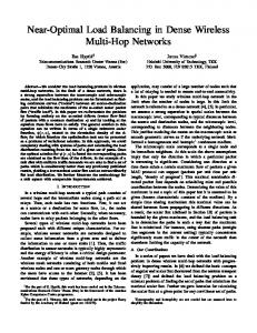
In this case, Ee is the sensor node operating energy consumption and εa is a sensor node signal amplification coefficient. Step 5: Compare the ranks of the thus-obtained number of transmission power value groupings, and settle on the sink node allocation candidate that has many 1-coverage sensor node groups that can perform efficient communications as the sink node allocation position. Subsequently, gather data and detect a number of sensor nodes where the decrease in residual power is relatively large, in order to balance the energy consumptions. Load balancing is done by appropriate selections of the 1-coverage sensor node groups that enable power saving of the sensor nodes and also the transmission power value groupings. b. Experimental Settings The settings for the virtual WSN of this paper are listed in Table 1. We set each energy consumption coefficient in Table 1 with reference to Document [20] and MICA2. MICA2 is a platform for sensor networks that is distributed by the US company Crossbow Technology, Inc., which provides nodes that are generally utilized as sensor nodes. We also set the parameters for the sensor nodes from consideration of comparisons between previous WSN research and a conventional method [14]. The parameter settings in the experiments on the improved ABC algorithm are listed in Table 2. We set the values for the parameter ec that determines convergence on the suboptimal solution and the parameter Ts that determines the specialist search
1547
Masato Noto and Seiji Yoneda, OPTIMAL SINK NODE ALLOCATION FOR BALANCING COMMUNICATION LOAD IN A WIRELESS SENSOR NETWORK
region with reference to Document [14]. We performed each experiment 50 times. The distribution after random allocation of the sensor node group has ended is shown in Figure 1. Table 1: Simulation parameters Sensor node allocation method Field size [m] Number of sensor nodes Number of sink nodes Communication radius [m] Sensing radius [m] E e [nJ/bit]
Random 1000 × 1000 1000, 1500, 2000 10 0 to 100 0, 25, 50 50
ε a [pJ/bit/m2] Packet size [bit]
100 128
Table 2: Simulation parameters for ABC algorithm Each colony size [N S ] Employed bees Onlooker bees α Tm ec Ts
1548
100 50% of colony size 50% of colony size 10 (0.1 × N S ) 3000 20 30.0
INTERNATIONAL JOURNAL ON SMART SENSING AND INTELLIGENT SYSTEMS VOL. 6, NO. 4, SEPTEMBER 2013
Figure 1. Sensor node allocation diagram c. Experimental Results and Discussion The 1-coverage sensor node group obtained by using the improved sequential activation method is shown in Figure 2. Originally, there are 1500 sensor nodes operating in sensing mode in the field, but that number has been reduced to approximately 1100 in Figure 2. With the improved sequential activation method, a number of sensor node groups of this type can be detected.
1549
Masato Noto and Seiji Yoneda, OPTIMAL SINK NODE ALLOCATION FOR BALANCING COMMUNICATION LOAD IN A WIRELESS SENSOR NETWORK
Figure 2. Example of 1-coverage sensor node group An example of ten sink node allocation candidates that were derived on the basis of the number of hops and constraint conditions, using a 1-coverage sensor node group, is shown in Figure 3. The circles in the figure denote sensor nodes, the squares show the sink node allocation candidates that were allocated regularly, and the stars show the sink node allocation candidates derived by the proposed method. Next, we attempt to use the proposed method to derive transmission power value groupings from the sink node allocation candidates, and determine that a sink node allocation candidate having a favorable transmission power value grouping is the final sink node allocation position. The results of comparing allocations by the conventional method, using only a regular sink node allocation and the number of hops, and those by the proposed method are demonstrated below from the viewpoints of data arrival rate and total network (NW) energy consumption. Note that the data arrival rate is given by Equation (7): Da = Dr / Dg
(7)
Dg is the number of data points generated by sensor nodes in sensing mode per unit time and Dr is the sum of the number of data points received by each sink node per unit time.
1550
INTERNATIONAL JOURNAL ON SMART SENSING AND INTELLIGENT SYSTEMS VOL. 6, NO. 4, SEPTEMBER 2013
Figure 3. Sink node allocation status Shifts in the arrival rates of data arriving at each sink node are shown in Figure 4. RA denotes the results for a regular allocation of nodes, CM denotes those for the conventional method, and PM denotes those for the proposed method, where the sensing radius of each sensor node in accordance with the proposed method is set to 25 m. With the regular allocation, a bias in communications load is generated towards sensor nodes in the vicinity of the sink nodes, resulting in sensor nodes dropping out of the NW at an early stage. With the conventional method, a constant load distribution and extended operation effect are seen, but we can confirm that leads to a gradual deterioration in the data arrival rate, regardless whether high-granularity control is enabled for the sensor nodes. With the proposed method, on the other hand, bias in the communications loading can be suppressed and efficient communications are implemented up to the point just before the residual power in load-concentration nodes disappears, by allocating sink nodes at appropriate positions, making some of the sensor nodes go into sleep mode as appropriate, and also retaining a number of transmission power value groupings for the sensor nodes.
1551
Masato Noto and Seiji Yoneda, OPTIMAL SINK NODE ALLOCATION FOR BALANCING COMMUNICATION LOAD IN A WIRELESS SENSOR NETWORK
Figure 4. Shifts in data arrival rate Changes in data arrival rate caused by changing the number of sensor nodes allocated in the field to 1000, 1500, and 2000, which changes the sensor node density, are shown in Figure 5. With a WSN, since any increase in the number of sensor nodes allocated to the field is linked to an increase in the relay node candidates, a large number of sensor nodes has the benefit of a load distribution effect. With the conventional method, however, since the objective is to minimize the number of hops, the communications radius of most of the sensor nodes is set in the vicinity of the maximum of 100 meters. For that reason, any increase in the number of sensor loads will cause an increase in the communications load applied to a specific relay node and a drop in the load distribution effect. With the proposed method, on the other hand, only sensor nodes that satisfy the WSN sensing requirements change their sensing mode, even if the number of sensor nodes allocated to the field increases, so it is difficult for redundant communications to be generated. In addition, since there is a number of routings with high load distribution capabilities, it is clear that an increase in the number of sensor nodes will not have a large effect. When the number of nodes has decreased, however, a deterioration in load distribution performance is seen. This is considered to be linked to the increase in load imparted to each sensor node and the deterioration in the load distribution capabilities, because a large number of sensor nodes must go into sensing mode in order to satisfy the WSN sensing requirement.
1552
INTERNATIONAL JOURNAL ON SMART SENSING AND INTELLIGENT SYSTEMS VOL. 6, NO. 4, SEPTEMBER 2013
Figure 5. Effects of node density on data arrival rate Table 3 shows a summary of the total energy consumptions of the entire NW for a single data collection in an environment in which 1500 sensor nodes are allocated. BEST in the table is the best value in 50 runs, and AVE is the average value. The alphabetic characters (A, B, C) are identifiers of the 1-coverage sensor node groups that were obtained. From consideration of the results, we see that the regular allocation involves a large communications load throughout the NW. With the conventional method, a constant communications load decrease effect is seen, but since all of the sensor nodes are driven, the total NW energy consumption remains large. With the proposed method, we succeed in restraining the total NW energy consumption to below that of the regular allocation and the conventional method. The proposed method enables searching of a number of 1-coverage sensor node groups and also enables searching of a number of transmission power value groupings linked to one of those 1-coverage sensor node groups. The problem of the possibility of requiring a number of highly similar suboptimal solutions in a search of number of transmission power value groupings, which was an issue with conventional transmission power control methods, can be greatly improved by implementing 1-coverage.
1553
Masato Noto and Seiji Yoneda, OPTIMAL SINK NODE ALLOCATION FOR BALANCING COMMUNICATION LOAD IN A WIRELESS SENSOR NETWORK
Table 3: Total NW energy consumptions Method RA CM Solution 1 PM A Solution 2 Solution 3 Solution 1 PM B Solution 2 Solution 3 Solution 1 Solution 2 PM C Solution 3
Total energy consumption BEST [mJ] AVE [mJ] 45.259 53.04 25.877 26.427 12.813 12.835 12.848 12.862 12.864 12.886 12.844 12.867 12.859 12.871 12.872 12.897 12.847 12.873 12.869 12.896 12.884 12.924
The results of the proposed method when the sensing radius is changed from 0, to 25, and to 50 meters are shown in Figure 6 and Table 4, as seen from the viewpoints of data arrival rate and total NW energy consumption. A sensing radius of 0 meters assumes a sensor that can only acquire data at close range. It is clear from these results that as the sensing radius becomes tighter, the period during which the data arrival rate is kept high is shortened and also the total NW energy consumption increases. This is because, when the sensing radius is 0 meters, all of the sensor nodes must participate in the 1-coverage, so there are no sensor nodes that can be set to sleep mode. Thus the communications load on relay nodes increases, which has an adverse effect on the load balancing of the sensor nodes. When the sensing radius expands, on the other hand, the number of sensor nodes that can be set to sleep mode increases and the total NW energy consumption decreases. There are a number of load distribution techniques in accordance with this proposed method, but it is thought that the results of changing the sensing radius have a large effect.
1554
INTERNATIONAL JOURNAL ON SMART SENSING AND INTELLIGENT SYSTEMS VOL. 6, NO. 4, SEPTEMBER 2013
Figure 6. Effects of sensing radius on data arrival rate Table 4: Effects of sensing radius on total NW energy consumption Sensing radius 0 [m] Solution 1 25 [m] Solution 2 Solution 3 Solution 1 Solution 2 50 [m] Solution 3
Total energy consumption BEST [mJ] AVE [mJ] 23.128 24.493 12.813 12.835 12.862 12.848 12.864 12.886 7.997 8.026 8.042 8.073 8.126 8.096
From the above results, we can say that the proposed method is more effective than the conventional method from the viewpoint of implementing extended operation and power saving performance in an environment in which a large number of sensor nodes are allocated in a field. In addition, increases in the total NW energy consumption can be restrained since sensor nodes can be efficiently selected for setting into sleep mode by performing a 1-coverage sensor node group search, even when there is a dramatic increase in the number of sensor nodes allocated to the field. Furthermore, extremely detailed drive control of the sensor nodes can be done by creating a number of routings to enable processing for load balancing and designing transmission power value groupings from consideration of the degree of contribution to the 1-coverage routing of each sensor node. Since the assigning of 1-coverage sensor node groups that is central to the
1555
Masato Noto and Seiji Yoneda, OPTIMAL SINK NODE ALLOCATION FOR BALANCING COMMUNICATION LOAD IN A WIRELESS SENSOR NETWORK
proposed method largely depends on the sensing radius that each sensor node has as an intrinsic parameter, it is possible that the utility of the proposed method cannot be sufficiently exhibited, depending on the application used and the sensor node allocation. However, since it is possible to perform suboptimal allocation of sink nodes and derive transmission power value groupings, even in such an environment, the proposed method can be said to have flexibility, largely independent of the design environment. V.
CONCLUSIONS
In this paper, we have proposed a method of deriving the optimal allocation positions of a number of sink nodes, by using an improved sequential activation method and an improved ABC algorithm, in order to implement extended operation of a WSN in an environment in which sensor nodes are allocated at random in the WSN which has a number of sinks. We used computer simulation to compare the method with the conventional method that determines sink node allocation position by using only the number of hops, and have confirmed that the proposed method maintains the data arrival rate at a higher level and reduces the total NW energy consumption. From this, we find that the proposed method makes it possible to distribute the loads of each sensor node, particularly those of load-concentration nodes that exist in the vicinity of sink nodes. In addition, the assigning of 1-coverage sensor node groups is linked to ensuring diversity of a number of transmission power value groupings obtained by the improved ABC algorithm, with the objective of efficiently implementing sleep control, so this method is also said to be extremely applicable to this problem. A future challenge is to investigate whether the proposed method can cope with a huge variety of requirements, since a large-scale, complex WSN designed for the use of a number of different sensor nodes would be required to handle differences in generated data volumes and the reception of only specific data. We also intend to improve the search and specialization performances of the improved ABC algorithm, organize it so it can solve a number of designed problems at the same time in the WSN assumed for this paper, and obtain Pareto optimality perceived as a multiobjective optimization problem. Furthermore, we will consider the robustness, flexibility, and expandability of the proposed method by evaluating items other than those evaluated by this study, to increase the feasibility of the proposed method.
1556
INTERNATIONAL JOURNAL ON SMART SENSING AND INTELLIGENT SYSTEMS VOL. 6, NO. 4, SEPTEMBER 2013
REFERENCES [1] T. Wada, I-Te Lin, and I. Sasase, “Asynchronous receiver-initiated MAC protocol exploiting stair-like sleep in wireless sensor networks”, IEICE Transactions on Communications, vol. E96– B, no. 1, pp. 119–126, Jan. 2013. [2] H. Yueshun and Z. Wei, “The research on wireless sensor network for landslide monitoring”, International Journal on Smart Sensing and Intelligent Systems, vol. 6, no. 3, pp. 867–887, Jun. 2013. [3] C. Chunling, W. Hao, Y. Zhihu, Z. Dengyin, and X. Xiaolong, “Outer detection based on similar flocking model in wireless sensor networks”, International Journal on Smart Sensing and Intelligent Systems, vol. 6, no. 1, pp. 18–37, Feb. 2013. [4] A. F. Salami, H. Bello-Salau, F. Anwar, and A. M. Aibinu, “A novel Biased Energy Distribution (BED) technique for cluster-based routing in wireless sensor networks”, International Journal on Smart Sensing and Intelligent Systems, vol. 4, no. 2, pp. 161–173, Jun. 2011. [5] S. Madden, M. J. Franklin, J. M. Hellerstein, and W. Hong, “The design of an acquisitional query processor for sensor networks”, Proc. 2003 ACM SIGMOD International Conference on Management of Data, pp. 491–502, Jun. 2003. [6] Q. Huang, C. Lu, and G. Roman, “Spatiotemporal multicast in sensor networks”, Proc. First ACM SenSys Conference, pp. 218–229, Nov. 2003. [7] A. Woo, T. Tong, and D. Culler, “Taming the underlying challenges of reliable multihop routing in sensor networks”, Proc. First ACM SenSys Conference, pp. 14–27, Nov. 2003. [8] A. Rajgarhia, F. Stann, and J. Heidemann, “Privacy sensitive monitoring with a mix of IR sensors and cameras”, Proc. Second International Workshop on Sensor and Actor Network Protocols and Applications, pp. 21–29, Aug. 2004. [9] Y. Ohtaki, N. Wakamiya, M. Murata, and M. Imasa, ”Scalable and efficient ant-based routing algorithm for ad-hoc networks”, IEICE Transactions on Communications, vol. E89-B, no. 4, pp. 1231–1238, Apr. 2006.
1557
Masato Noto and Seiji Yoneda, OPTIMAL SINK NODE ALLOCATION FOR BALANCING COMMUNICATION LOAD IN A WIRELESS SENSOR NETWORK
[10] S. Okdem, D. Karaboga, and C. Ozturk, “An application of wireless sensor network routing based on artificial bee colony algorithm”, Proc. 2011 IEEE Congress on Evolutionary Computation, pp. 326–330, Jun. 2011. [11] S. R. Gandham, M. Dawande, R. Prakash, and S. Venkatesan, “Energy efficient schemes for wireless sensor networks with multiple mobile base stations”, Proc. IEEE 2003 Global Communications Conference, vol. 1, pp. 377–381, Dec. 2003. [12] E. I. Oyman and C. Ersoy, “Multiple sink network design problem in large scale wireless sensor networks”, Proc. 2004 IEEE International Conference on Communications, vol. 6, pp. 3663–3667, Jun. 2004. [13] H. Dubois-Ferriere, D. Estrin, and T. Stathopoulos, “Efficient and practical query scoping in sensor networks”, Proc. IEEE International Conference on Mobile Ad-hoc and Sensor Systems, pp. 564–566, Oct. 2004. [14] A. Utani and H. Yamamoto, “Particle swarm optimization for computing plural acceptable solutions and its application to sink node allocation problem in wireless sensor network with multiple sinks”, IEICE Trans. D, vol. J93–D, no. 5, pp. 555–567, May 2010. (in Japanese) [15] D. Karaboga and B. Basturk, “On the performance of Artificial Bee Colony (ABC) algorithm”, Applied Soft Computing, vol. 8, no. 1, pp. 687–697, Jan. 2008. [16] A. Keshavarzian, H. Lee, and L. Venkatraman, “Wakeup scheduling in wireless sensor networks”, Proc. 7th ACM International Symposium on Mobile Ad Hoc Networking and Computing, pp. 322–333, May 2006. [17] J. Ma, W. Lou, Y. Wu, X.-Y. Li, and G. Chen, “Energy efficient TDMA sleep scheduling in wireless sensor networks”, Proc. IEEE INFOCOM 2009, pp. 630–638, Apr. 2009. [18] R. Katsuma, Y. Murata, N. Shibata, K. Yasumoto, and M. Ito, “Extending k-coverage lifetime of wireless sensor networks with surplus nodes”, Proc. 5th International Conference on Mobile Computing and Ubiquitous Networking, pp. 9–16, Apr. 2010. [19] W. R. Heinzelman, A. Chandrakasan, and H. Balakrishnan, “Energy-efficient communication protocol for wireless micro sensor networks”, Proc. 33rd Hawaii International Conference on System Sciences, pp. 3005–3014, Jan. 2000. [20] G. Wang, G. Cao, T. La Porta, and W. Zhang, “Sensor relocation in mobile sensor networks”, Proc. IEEE INFOCOM 2005, vol. 4, pp. 2302–2312, Mar. 2005.
1558