International Journal of Thermal Sciences 136 (2019) 267–277
Contents lists available at ScienceDirect
International Journal of Thermal Sciences journal homepage: www.elsevier.com/locate/ijts
Optimal spacing in heat generating parallel plate channel: A conjugate approach
T
A.D. Mohamme Samee, Asif Afzal, M.K. Ramis∗, R.K. Abdul Razak Department of Mechanical Engineering, P. A. College of Engineering, Mangaluru, (Affiliated to Visvesvaraya Technological University, Belagavi), India
A R T I C LE I N FO
A B S T R A C T
Keywords: Conjugate heat transfer Optimal spacing Forced convection Coolants2010 MSC: 00-01 99-00
The prime objective of this investigation is to address the problem of optimum spacing of channels formed by parallel plates having volumetric heat generation, subjected to conjugate forced convection-conduction cooling. Assuming non uniform volumetric heat generation in the plate, the two dimensional equation governing the temperature distribution in the solid domain are solved simultaneously with stream function, vorticity transport, and energy equation for the flow and thermal fields of the fluid domain, using appropriate finite difference method. Keeping aspect ratio ( Ar ) of the plate constant, results are presented in the form of effect of conductionconvection parameter (Ncc ), total heat generation parameter (Qt ), Reynolds number (ReH ) on the optimum spacing of the plates, for various Prandtl number (Pr ) representing the coolants liquid Sodium, SodiumePotassium, Lead and Helium. It is concluded that the optimum spacing between the plates (Bopt ) is independent of Qt and Ncc , whereas decreases with increase in ReH , and Pr . It is also concluded that, Helium acts as the best among all the coolants considered in this study, whereas Lead serves to be the best among all liquid metal coolants.
1. Introduction Obtaining the optimal spacing in parallel plate channel has become a topic of interest for many investigators from few decades, as it plays a vital role in the field of electronics industries, solar power applications, heat exchanger, fins and nuclear power industries. Optimal spacing also leads to miniaturization of devices, reduction in manufacturing cost and increase the life of materials with maximal and efficient rate of heat transfer. In recent past a rapid growth in nuclear and electronics industries has put forth a question in front of engineers to achieve the most efficient, optimal and safe design. Many investigators have paid their attention towards problem of optimal spacing between parallel plates pertaining to conjugate and non-conjugate heat transfer and few such studies are enumerated below. Bar-Cohen and Rohsenow [1] conducted a study on free convection between vertical parallel plates array subjected to uniform heat flux and uniform wall temperature condition by considering symmetric and asymmetric heating of plates. Anand et al. [2], presented a problem of optimal spacing with natural convection flow between single channel having uniform heat flux and uniform wall temperature imposed condition along with asymmetric channel heating. Bejan and Sciubba [3] reported the problem of spacing in parallel plates with forced convection cooling, and found that optimal spacing is dependent on length of ∗
plate, pressure head across the plates and coolant properties like viscosity and thermal diffusivity. They also stated that conditions over the surface do not have much impact on heat transfer rate and optimal spacing. Kim and Anand [4] investigated the effect of conduction in a wall exposed to laminar free convection flow between asymmetrically heated plates with constant heat flux. Bello-Ochende and Bejan [5] investigated the problem of optimization of stack of parallel plates with mixed convection cooling effects. A correlation for optimal spacing is proposed which fill the gap between free and forced convection. In another study Bejan and Ledezma [6] studied the optimizing techniques for electric devices generating heat and concluded that the pumping power required for cooling can be reduced to minimum value by obtaining the most optimized contact area. It was also stated that optimal contact area is independent of flow condition (mixed or unmixed). Fowler et al. [7], studied experimentally and numerically the optimal arrangement of staggered parallel plates subjected to forced convection flow with volume constraints. He reported that there exists an optimal way to place the plates and a correlation for optimal spacing having maximum heat transfer was proposed. Morrone et al. [8], investigated numerically the problem of optimization in case of symmetrically heated parallel plates with uniform heat flux subjected to free convection flow of air. From the obtained results it was concluded that the spacing between the plates is a function of Grashoff number and mass flow rate.
Corresponding author. E-mail address:
[email protected] (M.K. Ramis).
https://doi.org/10.1016/j.ijthermalsci.2018.10.025 Received 15 June 2017; Received in revised form 10 October 2018; Accepted 18 October 2018 1290-0729/ © 2018 Elsevier Masson SAS. All rights reserved.
International Journal of Thermal Sciences 136 (2019) 267–277
A.D. Mohamme Samee et al.
Morega et al. [9], presented a study on optimal arrangement of stack of parallel plates subjected to forced convection. The arrangement is made in such a way that the resistance to thermal field in stack of plates and flow of fluid is least. Chen et al. [10], carried out an experimental investigation to determine the most optimal arrangement of electrically heated obstacles placed in a channel subjected to forced convection flow. It was suggested that the conventional equi-spaced arrangement is not convenient for maximum heat transfer. Silva et al. [11], used constructal theory to place optimally the heat sources on wall with forced convection flow and stated that by increasing the conductivity between wall and heat sources the temperature of hot spots on the wall can be decreased. Sun et al. [12], numerically addressed the problem of optimal spacing in an array of isothermal plates subjected to flow of air under mixed, laminar, incompressible flow condition. The study concluded that the optimal spacing value reduces in mixed convection compare to forced convection. Hotta [13] demonstrated steady state experimental study for a horizontal channel fixed with discrete heat sources of different sizes subjected to mixed convection flow regime. A correlation is developed for optimal configuration of heat sources by considering the effect of surface radiations. Turkoglu et al. [14], reported a numerical heat transfer analysis for mixed convection laminar flow in a vertical channel with discrete heat source fitted in one of the wall with isothermal condition on another wall. A more realistic approach by considering the heat transfer in the wall was adopted by several researchers, employing a conjugate approach and a few such studies are mentioned below. Watson et al. [15], presented a conjugate mixed convection laminar heat transfer analysis for a set of vertical channel with planar heat source on one surface of each plate. Wilson et al. [16], addressed a conjugate mixed convection heat transfer analysis for two dimensional steady laminar flow of air in a heated horizontal channel both experimentally and numerically. It was shown that consideration of conjugate condition greatly influence the temperature distribution as well as heat transfer rate. Rao et al. [17], presented a numerical study on conjugate mixed convection with two-dimensional steady laminar, incompressible flow of air in a vertical channel with flush mounted heat generating heat sources in each wall by considering the effect of radiation. A correlation is developed for maximum temperature in left and right walls of the channel. Londhe et al. [18], numerically addressed a problem of conjugate heat transfer in a discretely heated vertical channel under laminar mixed convection flow with consideration of radiation effects. It is revealed that radiation cannot be ignored in all regimes of mixed convection. Bautista [19] used an analytical and numerical approach to address the problem of rectangular channel with internal heat generating source under laminar fully developed forced flow condition. Barletta et al. [20], carried out conjugate forced convection laminar heat transfer investigation numerically for a parallel plate channel whose external surface is subjected to longitudinally sinusoidal temperature variation. Complex temperature analytical method and finite element method was used and the temperature field and local Nu were determined. Alves et al. [21], investigated conjugate cooling of a single block heater mounted on a conductive wall of a parallel plate channel under laminar forced convection with distinct air flow constraints: fixed flow rate, fixed channel flow pressure drop, and fixed pumping power. Sucec [22] presented a numerical study on a transient heat transfer in a parallel plate duct subjected to flowing fluid when there is sinusoidal heat generation with axial position in the wall. Other few numerical studies pertinent to conjugate conduction-convection regimes in which optimal configuration, with or without the effect of radiation was reported in Refs. [23–29]. The above literature survey reveals that, not a single study pertinent to optimal spacing of parallel plate channel under conjugate forced convection-conduction regimes having volumetric energy generation in the plate is reported. The numerical investigation pertinent to conjugate optimum spacing studies reported in Refs. [17,18and19] has considered the effect of internal heat generation but limited to flush
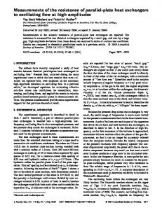
Fig. 1. Physical model.
mounted and protruding heat source in the wall. Though Sucec [22], has considered volumetric energy generation within the plates forming the channel, the study is based on the assumption of negligible transverse temperature gradient within the plate and a highly idealized flow and thermal fields over it. Also the study is limited to a single channel without any optimum spacing investigation. Therefore owing to the importance of application in stack of fuel plates in a research reactor [30] and the inadequacies reported above is the motivation behind this work. The objective of present investigation is to study the effect of various parameters- ReH , Ncc , Qt and keeping constant Ar , on optimum spacing of channel formed by parallel plates having volumetric energy generation cooled with different coolants (Liquid Sodium, Sodium-potassium, Lead and Helium) under laminar conjugate forced convection conduction regime. 2. Mathematical modelling Fig. 1 depicts the physical model of the conjugate heat transfer problem which mainly consists of an array of vertical parallel plates with volumetric energy generation. The height and the thickness of each plate are H and 2W, respectively while the plate-to-plate spacing is 2b as shown in the figure. The coolant enters the channels formed by 268
International Journal of Thermal Sciences 136 (2019) 267–277
A.D. Mohamme Samee et al.
the successive plates at temperature T∞ and velocity U∞ . Under steady state conditions, the energy generated in each plate is initially conducted in it and then dissipated from its lateral surface to the upward moving stream of coolant by forced convection so as to maintain the maximum temperature in the plate below the allowable limit. While the leading edge of the plate is assumed to be maintained at free stream temperature of the coolant T∞ , and at the trailing edge of the plate zero Neumann boundary condition is assumed. In order to reduce the complexity of the above conjugate heat transfer problem the following assumptions are made.
• The plate material is isotropic and homogeneous. • The flow and thermal fields are steady and two dimensional. • A Newtonian, laminar, viscous and incompressible flow regime is considered in the channel. • The thermo-physical properties of coolant and plate are constant. Since the intermediate plates in the array and the channels formed by them are identical, the temperature distribution in each plate and the flow and thermal fields within each channel are expected to be symmetric about respective vertical axis. Thus, for the present study of the conjugate conduction-forced convection problem as described above, it is sufficient that one considers the solution domain comprising of half of the plate and its adjacent half of the fluid domain within a particular channel, which is shown in detail in Fig. 2. The equivalent mathematical model of the physical problem mentioned above is obtained by superimposing the Cartesian coordinate system on the plate in such a way that the origin is at the bottom right corner of the plate with X as vertical and Y as horizontal axis. Taking into consideration the assumptions stated above, the steady state temperature distribution governing equation in a plate having non-uniform volumetric energy generation can be obtained in its non-dimensional form as
∂2θs ∂ 2θ + C 2s + CQ (X ) = 0 ∂X 2 ∂Ys
(1)
where θs represents the temperature in the plate and C is a constant related to aspect ratio of the plate. The function Q (X ) in the source term is a cosine function of the vertical coordinate X and can be expressed as [31].
1 Q (X ) = Qmax cosπ ⎛ − X ⎞ ⎠ ⎝2
(2)
Since the volumetric energy generation in the plate is non-uniform, an appropriate parameter based on total energy generated within each plate is defined, which is termed as ‘total energy generation parameter’ Qt . The value of Qt is essentially obtained by integrating the volumetric energy generation function Q (X ) over the entire volume of each plate which yields an expression in terms of maximum value of volumetric energy generation function Qmax . The parameter Qt is expressed as
Qt =
2 Qmax π
Fig. 2. Computational domain.
the flow and thermal fields in the channel formed by two adjacent parallel plates can be obtained in their dimensionless form as
Streamfunction:
(3)
∂ 2Ψ ∂ 2Ψ + = −Ω 2 ∂X ∂Y f2
Keeping in mind the plate part of the solution domain as mentioned earlier in this section, the solution of equation (1) can be obtained by imposing the following most appropriate boundary conditions:
Ys = −1; 0 ≤ X ≤ 1,
∂θs =0 ∂Ys
Vorticity − Transport: U
(4)
Ys = 0; 0 ≤ X ≤ 1, θs = θf
(5)
X = 0; −1 ≤ Ys ≤ 0, θs = 0
(6)
∂θs =0 ∂X
∂ 2Ω ⎞ ∂Ω ∂Ω 1 ⎛ ∂ 2Ω + +V = ∂X ∂Yf ReH ⎜⎝ ∂X 2 ∂Y f2 ⎟⎠
(9)
Energy: U
X = 1; −1 ≤ Ys ≤ 0,
(8)
(7)
∂θf ∂X
+V
∂θf ∂Yf
=
2 ∂2θf ⎞ ⎛ ∂ θf + ⎜ 2 ReH Pr ⎝ ∂X ∂Y f2 ⎟⎠
1
(10)
Equations (8)–(10) can be solved by imposing physical conditions all along the boundaries of the flow and thermal fields in the channel. However, in the present study, in order to impose physically
Implementing stream function-vorticity formulation and invoking appropriate approximations and assumptions, the equations governing 269
International Journal of Thermal Sciences 136 (2019) 267–277
A.D. Mohamme Samee et al.
flow domain governing equations 8 and 9 in the coolant, along with the thermal domain governing equation 10 in the coolant, the equations being coupled are solved simultaneously by using finite difference method in conjunction with an iterative solution procedure and by fulfilling the continuity conditions of temperature and heat flux at the solid-fluid interface. Accordingly, equation (1) together with its boundary conditions given in equations (4)–(7) and equation (8) along with its boundary conditions specified in equations (11)–(15) are discretized using second-order accurate finite difference schemes and the resulting system of linear algebraic equations are solved using ‘Thomas Algorithm’ and by employing ‘Line-by-Line Gauss-Seidel’ iterative solution procedure. On other side, the pseudo-transient form of equations (9) and (10) along with their boundary conditions presented in equations (11)–(15) are discretized using Alternating direction implicit (ADI) scheme and the resulting system of finite difference equations are solved using ‘Thomas Algorithm’.
meaningful conditions at the boundary corresponding to the outlet of the channel, the actual outflow boundary of the flow and thermal fields are located further downstream at a distance lo from the trailing edge of the plate and the height of this extended domain is determined by numerical experimentations. As the flow and thermal fields in the channel is expected to be symmetric about its vertical central line, the computational fluid domain considered in the present study is also corresponding to the half of the channel and thus, the conditions of symmetry of flow and thermal fields can be imposed on this line of symmetry. The boundary conditions suitable for the present conjugate heat transfer study can be presented in dimensionless form as.
Yf = 0; 0 ≤ X ≤ 1, Ψ= 0, Ω= −
1 ∂θs ∂2Ψ ∂θf , = Ncc ∂Ys ∂Y f2 ∂Yf
Yf = 0; 1 ≤ X ≤ (1 + Lo), Ψ= 0, Ω= 0,
∂θf ∂Yf
Yf = B; 0 ≤ X ≤ (1 + Lo), Ψ= Ψb, Ω= 0,
(11)
=0
∂θf ∂Yf
(12)
3.1. Validation of computer code
=0
(13)
∂Ψ X = 0; 0 ≤ Yf ≤ B, = 0, Ω= 0, θf = 0 ∂X
X = (1 + Lo); 0 ≤ Yf ≤ B,
The mathematical formulation of the conjugate conduction forced convection heat transfer problem in a channel formed by two adjacent heat generating parallel plates is identical with that of a single heat generating plate washed by upward moving stream of coolant with the exception that for a given set of parameters, the value of plate-to-plate spacing has to be suitably chosen. Thus, the numerical results presented and discussed in this paper have been computed using a code developed in a stage wise manner and can take care of conjugate/non conjugate natural, forced and mixed convective heat transfer problems in rectangular geometry having different boundary conditions, merely by manipulating the choice of certain flag variables. Therefore this indigenous code is validated at different stages of its development with various benchmark problems. Initially the code is validated with the results of popular differentially heated square cavity problem reported by Vahl Davis [33]. The results shown in Table 1 are in excellent agreement with that of Vahl Davis [33]. Further the validity of the coupled code of solid and fluid domain is checked by comparing the temperature profile at solid fluid interface with that of Vynnycky et al., [32]. The comparative results are in excellent agreement, as shown in Fig. 3, which well establishes the validity for the entire code of the present study.
(14)
∂θf ∂Ψ ∂Ω = 0, = 0, =0 ∂X ∂X ∂X
(15)
The non-dimensional variables and parameters used in equations (1)–(15) are defined as
X=
y y x Ys = Yf = H W H
(16)
U=
u v T − T∞ V= θ= U∞ U∞ To − T∞
(17)
Ar =
H b l B = Lo = o 2W H H
Q (X ) =
ReH =
(18)
qmax W 2 q‴ (x ) W 2 Qmax = ks (To − T∞) ks (To − T∞)
(19)
Kf W U∞ H ⎛ ⎞ Ncc = ν Ks ⎝ H ⎠
(20)
It is worth mentioning here that the boundary conditions at the downstream region of the computational domain at Yf = 0 are essentially based on the assumption of no heat flux, no normal outflow and no shear stress which are commonly employed in the literature [32]. Although, the condition of zero shear stress at the down stream of the plate appears to be somewhat unrealistic, it should have negligible effect on the heat dissipation rate from the plate for convection dominated flows. Equation (1) used for the temperature distribution in the plate and Equations 8–10 for the flow and thermal fields in the coolant flowing through the channel are coupled and therefore, the solutions of these equations have to be obtained simultaneously by employing appropriate numerical schemes and an iterative solution procedure.
3.2. Mesh independence test In the thermal and flow field of both plate and channel part of computational domain, the steep gradients of dependent variables are resolved by superimposing with a finite difference mesh having variable grid size in its transverse direction while keeping the grid size uniform in its longitudinal direction. Accordingly, denser grids are chosen towards the solid-fluid interface while keeping the grids coarser away from it. However, this grid model will strongly depend on the channel width and the flow ReH . Thus, for every set of these parameters, a series of grid independence tests are conducted numerically to arrive at an optimum grid model to be chosen for further computation. Figs. 4 and 5 illustrate one such mesh independence test performed for B = 0.4 and ReH = 1000 while keeping the values of Ar , Ncc , Pr , and Qt constant at 10, 0.40, 0.005, and 0.40 respectively. Fig. 4 depicts the transverse temperature profiles at the axial location X = 0.50 in the plate for three
3. Solution method The heat conduction governing equation 1 in the fuel element, the Table 1 Validation of average NuH with that of Vahl Davis [33]. NuH at Ra = 103
NuH atRa = 105
NuH at Ra = 10 4
Presentstudy
VahlDavis [33]
Presentstudy
VahlDavis [33]
Presentstudy
VahlDavis [33]
1.1517
1.1160
2.3158
2.2420
4.7860
4.5560
270
International Journal of Thermal Sciences 136 (2019) 267–277
A.D. Mohamme Samee et al.
Table 2 Grid independence test at ReH = 1000, Ncc = 0.4, Ar = 10, Pr = 0.005. Grid Size
Qt in put
Qt from surface
Qt from bottom of the plate
Qt from plate
21 × 101 41 × 201 81 × 401
0.4 0.4 0.4
0.382112 0.385167 0.396089
0.002500 0.003100 0.003900
0.384612 0.385477 0.399988
different mesh sizes, i.e., 21 × 101, 41 × 201, and 81 × 401, while Fig. 5 shows the transverse temperature profiles at the same axial location X = 0.50 in the channel for three different grid sizes 61 × 121, 121 × 241, and 241 × 481. It is abundantly clear from these two figures that irrespective of the grid sizes used in both plate as well as channel parts of the computational domain, the respective profiles superimpose each other. Thus, keeping in view of a better resolution of the zero Neumann boundary conditions, grid sizes of 81 × 401 in the plate part of the computational domain and grid sizes of 121 × 241 in the channel part of computational domain is selected. In order to further establish the validity of grid sizes selected for the above said parameters the total heat generation parameter which is given as the input is compared with total heat carried away by upward moving coolant and heat lost by the leading edge of the plate. It is very apparent from Table 2 that almost total heat generated in the plate is convected away and the remaining lost is at the leading edge of the plate. The total matching of the input parameter indicates the grid size efficiency, where the truncation error and other errors are reduced to bear minimum.
Fig. 3. Validation of solid-fluid interface temperature profile with that of Vynnchky [32] for different conductivity ratio.
4. Results and discussion The prime objective of present numerical investigation is to study the effect of various parameters on the optimum spacing (Bopt ) of channel formed between vertical parallel plates having volumetric energy generation. Accordingly a steady state two dimensional laminar conjugate conduction forced convection flow problem with different coolants namely, liquid Sodium (Pr =0.00500), SodiumePotassium (Pr =0.00753), Lead (Pr =0.02252) and Helium (Pr =0.66600) is considered. The effects of parameters ReH , Pr , Ncc , and Qt on optimum spacing are analysed and discussed in this section.
Fig. 4. Transverse temperature profiles at X = 0.5 in the plate for different grid sizes.
4.1. Effect of Qt on Bopt Fig. 6 depicts the effect of total heat generation parameter Qt on
Fig. 5. Transverse temperature profiles at X = 0.5 in the coolant for different grid sizes. Fig. 6. Effect of Qt on Bopt for liquid Sodium. 271
International Journal of Thermal Sciences 136 (2019) 267–277
A.D. Mohamme Samee et al.
for different fluids, namely SodiumePotassium (Pr =0.00753), Lead (Pr =0.02252) and Helium (Pr =0.66600) respectively. Aspect ratio ( Ar ), Reynolds number (ReH ) and conduction convection parameter (Ncc ) are kept constant at values 10, 1000, and 0.4 respectively, while Qt is taken as 0.4, 0.45, 0.5, and 0.55 in all these studies. It is evident from these figures that Bopt is independent of total heat generation parameter (Qt ), as the NuH profile exactly overlap on each other. This effect can be attributed to the fact that ReH and Pr of the fluid being constant, velocity and total heat carrying capacity of fluid remains same, as a result of which thermal dissipation from the lateral surface of the plate to the coolant remains unchanged for all the values of Qt . Therefore a maximum NuH is noticed at that spacing of channel, where convective heat transfer dominance over conductive heat transfer reaches its maximum value, and this spacing is unaffected by Qt . However the optimum spacing is decreased with increased value of Pr , with Helium having minimum optimum spacing. This is very obvious from the physics of the problem that higher Pr indicates lower thermal diffusivity leading to decreased thermal boundary layer thickness and thus decreased optimum spacing. Another important observation from these figures is that, at higher Pr , the maximum NuH increases and reaches maximum for Helium. This is due to high ReH and decrease in flow passage area [34]. This decrease in flow passage area results in accumulation of heat, which further appears in the form of increased NuH . It is also evident that rate of increase in NuH corresponding to same increment in spacing, increases with increase in Pr .
Fig. 7. Effect of Qt on Bopt for liquid Sodium Potassium.
4.2. Effect of Ncc on Bopt Figs. 10–13 shows the effect of conduction convection parameter (Ncc ) on optimum spacing between the plates while Ar = 10, ReH = 1000, Qt = 0.4 for different coolants under consideration. It is quite clear that Figs. 10–13 are identical to Figs. 6–9 which leads to the conclusion that conduction-convection parameter have no effect on optimum spacing between the plates. It is also evident that for different coolants, the range and variation of NuH follows exactly the same pattern as that of Figs. 6–9. The physics explained in Figs. 6–9 holds good in these results too and therefore omitted for the sake of brevity. 4.3. Effect of ReH on Bopt Fig. 8. Effect of Qt on Bopt for liquid Lead.
Fig. 14 illustrates the variation of NuH with B while ReH = 500, Qt = 0.4, Ncc = 0.4, Ar = 10 for channel coolant Sodium (Pr =0.005). Figs. 15–17 shows the same as that of Fig. 14 but for different ReH i.e.
Fig. 9. Effect of Qt on Bopt for Helium.
optimum spacing between the plates (Bopt ), which is the spacing where Nusselt number (NuH ) is maximum, for liquid Sodium (Pr =0.00500) as the channel fluid. Figs. 7–9 illustrate the same as in that for Fig. 6 but
Fig. 10. Effect of Ncc on Bopt for liquid Sodium. 272
International Journal of Thermal Sciences 136 (2019) 267–277
A.D. Mohamme Samee et al.
Fig. 14. Effect of ReH on Bopt for liquid Sodium.
Fig. 11. Effect of Ncc on Bopt for liquid Sodium Potassium.
Fig. 15. Effect of ReH on Bopt for liquid Sodium.
Fig. 12. Effect of Ncc on Bopt for liquid Lead.
Fig. 16. Effect of ReH on Bopt for liquid Sodium.
Fig. 13. Effect of Ncc on Bopt for Helium. 273
International Journal of Thermal Sciences 136 (2019) 267–277
A.D. Mohamme Samee et al.
Fig. 17. Effect of ReH on Bopt for liquid Sodium.
Fig. 19. Effect of ReH on Bopt for liquid Sodium Potassium.
1000, 1500, and 2000 respectively. In contradiction to the effect of Qt and Ncc as observed in Figs. 6–13, the optimum spacing between the plates is influenced by ReH . It is important to note here that increase in ReH leads to decrease the optimum spacing but increases the corresponding NuH . The trait of increase in NuH with increase in ReH is due to increase in velocity of flow, whereas increase of ReH results in decreasing both momentum and thermal boundary layer thickness which is reflected in the form of decreased Bopt . Another important observation to be noted here is that at higher ReH the NuH is highly influenced by small variation in spacing between the plates. The range of parameters on abscissa and ordinate for Figs. 14–17 is an apparent evidence for this. However the decrease in NuH with an increase in plate spacing beyond Bopt becomes less predominant at all ReH . The influence of ReH on optimum spacing is depicted in Figs. 18–21 where all the parameters remains same as that of Figs. 14–17 except that the coolant considered is SodiumePotassium (Pr =0.00753). The influence of ReH is characterized by the same trend as observed in Figs. 14–17. However the effect of increase in Pr is apparent in the form of increased NuH and decreased optimum spacing as compared to Figs. 14–17. The influence of ReH on Bopt for same set of parameters, as mentioned in Figs. 14–21, except that the coolant taken is Lead (Pr =0.02252) is depicted in Figs. 22–25. As mentioned in the discussion of influence of Qt and Ncc on Bopt , Lead as a coolant gives an increased NuH and decreased optimum spacing. Figs. 26–29 depicts the effect of ReH on Bopt for Helium as the
Fig. 20. Effect of ReH on Bopt for liquid Sodium Potassium.
Fig. 21. Effect of ReH on Bopt for liquid Sodium Potassium.
coolant, keeping the other parameters Qt = 0.4, Ncc = 0.4, Ar = 10 and Pr = 0.66600 constant. A few observations from these figures are summarized below
Fig. 18. Effect of ReH on Bopt for liquid Sodium Potassium. 274
International Journal of Thermal Sciences 136 (2019) 267–277
A.D. Mohamme Samee et al.
Fig. 22. Effect of ReH on Bopt for liquid Lead.
Fig. 25. Effect of ReH on Bopt for liquid Lead.
Fig. 23. Effect of ReH on Bopt for liquid Lead.
Fig. 26. Effect of ReH on Bopt for Helium.
Fig. 24. Effect of ReH on Bopt for liquid Lead. Fig. 27. Effect of ReH on Bopt for Helium.
275
International Journal of Thermal Sciences 136 (2019) 267–277
A.D. Mohamme Samee et al.
increases the convective heat transfer coefficient. Another reason may be the steeper velocity gradient in transverse direction arising out of decreased boundary layer thickness. This velocity gradient results in release of kinetic energy into Helium gas molecules which will create the viscous shear force and this shear force increases the temperature of Helium gas. This rise in temperature of gas affects the NuH [34–37]. The effect of ReH and Pr on optimum spacing between the heat generating vertical parallel plates which is already discussed in above sections 4.1 to 4.3 is summarized briefly in Table 3. 5. Conclusion A numerical study on optimum spacing of channels formed by parallel plates having non uniform volumetric energy generation subjected to conjugate forced convection-conduction cooling by various coolants (Liquid Sodium, SodiumePotassium, Lead and Helium) has been presented in this paper. A full Navier stoke equation employing stream function vorticity formulation is solved by using appropriate finite difference schemes. Results are presented in detail for a wide range of parameters- ReH , Qt , Ncc keeping Ar constant for different coolants under study. From detail discussion of these results the following conclusions are drawn.
Fig. 28. Effect of ReH on Bopt for Helium.
• The optimum spacing (B • • • •
opt ) between heat generating parallel plate channel is strongly dependent on ReH and Pr , and it is independent of Qt and Ncc . Helium as coolant shows a maximum range of average NuH compared to other coolants considered in the present conjugate numerical investigation. The thermal boundary layer thickness is affected by coolants and for Helium this thickness is minimum compared to other coolants. Among the liquid metal coolants Lead gives higher range of average NuH compared to Sodium and Sodium-potassium with less value of optimum spacing between plates (Bopt ). Optimum spacing (Bopt ) between the plates decreases with increase in ReH and Pr with corresponding increase in the NuH .
Nomenclature
Fig. 29. Effect of ReH on Bopt for Helium.
• The influence of spacing is quite apparent on Nu • The optimum spacing stays very close to the solid fluid interface at high Re • The Nu corresponding to all Re is maximum for Helium, among H
H
H
H
the coolants considered.
The above observation of increased NuH for Helium is due to the decreased flow passage area which affects the total mass flow rate and thus causing the heating of fluid. This results in sudden increase in the temperature of Helium gas molecules and hence correspondingly
Symbol
Abbreviation
Ar b B H K lo Lo Ncc NuH Pr q‴ (x ) q‴ (x )max Q (X ) Qmax Qt ReH
Solid domain aspect ratio Half of the spacing between plates Half of the dimensionless spacing between plates Plate height Thermal conductivity Length of extended flow field after trailing edge Dimensionless length of extended flow field after trailing edge Conduction-convection parameter Average Nusselt number Prandtl number Volumetric energy generation function Maximum volumetric energy generation Dimensionless volumetric energy generation function Maximum volumetric energy generation parameter Total energy generation parameter Flow Reynolds number
Table 3 Effect of ReH and Pr on optimum spacing. Reynolds Number (ReH )
500 1000 1500 2000
Liquid-Sodium (Pr =0.00500)
SodiumePotassium (Pr =0.00753)
Lead (Pr =0.02252)
Helium (Pr =0.66600)
Bopt
NuH
Bopt
NuH
Bopt
NuH
Bopt
NuH
1.75 1.02 0.82 0.57
2.614 3.328 4.032 4.697
1.20 0.70 0.50 0.40
2.941 3.978 4.945 5.827
0.50 0.30 0.22 0.17
4.684 6.969 8.832 10.429
0.04 0.03 0.02 0.02
27.410 39.5610 48.352 56.432
276
International Journal of Thermal Sciences 136 (2019) 267–277
A.D. Mohamme Samee et al.
Ra T To u U U∞ v V x X y Y W θ ν Ψ Ω f opt s sf ∞
Rayleigh number Temperature Maximum temperature limit in plate Velocity component in vertical direction Dimensionless velocity component in vertical direction Free stream velocity Velocity component in horizontal direction Dimensionless velocity component in horizontal direction Vertical co-ordinate Dimensionless vertical co-ordinate Horizontal co-ordinate Dimensionless horizontal co-ordinate Half of the thickness of the plate Dimensionless temperature Kinematic viscosity of the coolant Dimensionless stream function Dimensionless vorticity Fluid domain Optimum Solid domain Solid-fluid interface Free stream
[14] H. Turkoglu, N. Yucel, Mixed convection in vertical channels with discrete heat source, Heat Mass Tran. 30 (1995) 159–166. [15] J.C. Watson, N.K. Anand, L.S. Fletcher, Mixed convective heat transfer between a series of vertical parallel plates with planar heat sources, ASME J. Heat Tran. 118 (1996) 984–990. [16] Wilson K.S. Chiu, Cristy J. Richards, Yogesh Jaluria, Experimental and numerical study of conjugate heat transfer in a horizontal channel heated from below, ASME J. Heat Trans. 123 (2001) 688–697. [17] C. Gururaj Rao, C. Balaji, S.P. Venkateshan, Effect of surface radiation on conjugate mixed convection in a vertical channel with discrete heat source in each wall, Int. J. Heat Mass Tran. 45 (2002) 3331–3347. [18] S.D. Londhe, C.G. Rao, Mixed convection with conduction and surface radiation in vertical channel with discrete heating, J. Inst. Eng. India Ser. C 94 (2013) 213–223. [19] O. Bautista, F. Mendez, Internal heat generation in a discrete heat source: conjugate heat transfer analysis, Appl. Therm. Eng. 26 (2006) 2201–2208. [20] A. Barletta, E. Rosi di Schio, G. Comini, P.D. Agaro, Conjugate forced convection heat transfer in plane channel:longitudinally periodic regime, Int J. Thermal Sci. 47 (2008) 43–51. [21] Thiago Antonini, A. Carlos, C. Altemani, Conjugate cooling of protruding Heater in a channel with distinct flow constraints, Global J. Res. Eng. Mech. Mech. Eng. 13 (2013). [22] J. Sucec, Unsteady forced convection with sinusoidal duct wall generation: the conjugate heat transfer problem, Int. J. Heat Mass Tran. 45 (2002) 16311642. [23] S.D. Londhe, C.G. Rao, Interaction of surface radiation with conjugate mixed convection from a vertical channel with multiple discrete heat sources, Heat Mass Tran. 50 (2014) 1275–1290. [24] Roy N. Mathews, C. Balaji, Numerical simulation of conjugate, turbulent mixed convection heat transfer in a vertical channel with discrete heat sources, Int. Commun. Heat ans Mass Tran. 33 (2006) 908–916. [25] B. Premchandran, C. Balaji, Conjugate mixed convection with surface radiation from a vertical channel with protruding heat sources, Numer. Heat Tran. A 60 (2011) 171–196. [26] T.V.V. Sudhakar, C. Balaji, S.P. Venkateshan, Optimal configuration of heat sources in a vertical duct under conjugate mixed convection using artificial neural network, Int J. Thermal Sci. 48 (2009) 881–890. [27] Premchandran, C. Balaji, Conjugate mixed convection with surface radiation from horizontal channel with protruding heat sources, Int. J. Heat Mass Tran. 49 (2006) 3568–3582. [28] Biagio Morrone, Natural convection between parallel plates with conjugate conductive effects, Numer. Heat Tran. A 40 (2001) 873–886. [29] T.V.V. Sudhakar, C. Balaji, S.P. Venkateshan, A heuristic approach to optimal arrangement of multiple heat sources under conjugate natural convection, Int. J. Heat Mass Tran. 53 (2010) 431–444. [30] R.H.S. Winterton, Thermal Design of Nuclear Reactors, Pergamon Press Ltd,Headington Hill Hall, Oxford, U.K, 1981, pp. 53–54. [31] M.M. El-Wakil, Nuclear Power Engineering, McGraw- Hill Book Company, New York, 1962, pp. 203–204. [32] M. Vynnycky, S. Kimura, K. Kanev, I. Pop, Forced convection heat transfer from flat plate: the conjugate problem, Int. J. Heat Mass Tran. 41 (1998) 45–59. [33] G.D. Vahl Davis, Natural convection of air in a square cavity: a bench mark numerical solution, Int. J. Numer. Methods Fluid. 3 (1983) 249–264. [34] M.M. El-Wakil, Nuclear Heat Transport, International Text Book Company, An Intext Publisher, 1971, p. 254. [35] A.D.M. Samee, A. Afzal, R.K. Abdul Razak, M.K. Ramis, Effect of Prandtl number on the average exit temperature of coolant in a heat-generating vertical parallel plate channel: a conjugate analysis, Heat Tran. Asian Res. 47 (4) (2018) 603619 https:// doi.org/10.1002/htj.21330. [36] R.K. Abdul Razak, A. Afzal, A.D. Mohammed Samee, M.K. Ramis, Investigation of dimensionless parameters and geometry effects on heat transfer characteristics of Liquid sodium flowing over a vertical flat plate, Heat Tran. Asian Res. (2018) 1–18 https://doi.org/10.1002/htj.21368. [37] A. Afzal, A.D. Mohammed Samee, R.K. Abdul Razak, M.K. Ramis, Effect of spacing on thermal performance characteristics of Li-ion battery cells, J. Therm. Anal. Calorim. (2018) 1–15 https://doi.org/10.1007/s10973-018-7664-2.
Acknowledgments This study was funded by AICTE New Delhi, INDIA (2015-16) scheme letter number 20/AICTE/RIFD/RPS(Policy-1)53/2013-14. References [1] A. Bar-Cohen, W.M. Rohsenow, Thermally optimum spacing of vertical, natural convection cooled, parallel plates, ASME J. Heat Tran. 106 (1984) 116–123. [2] N.K. Anand, S.H. Kim, L.S. Fletcher, The effect of plate spacing on free convection between heated parallel plates, ASME J. Heat Tran. 114 (1992) 515–518. [3] Adrain Bejan, Enrico Sciubba, The optimal spacing of parallel plates cooled by forced convection, Int. J. Heat Mass Tran. 35 (1992) 3259–3264. [4] S.H. Kim, N.K. Anand, Effect of wall conduction on free convection between asymmetrically heated vertical plates: uniform wall heat flux, Int. J. Heat Mass Tran. 33 (1990) 1013–1023. [5] T. Bello-Ochende, A. Bejan, Optimal spacing for mixed convection, ASME J. Heat Transfer 126 (2004) 956–962. [6] A. Bejan, G.A. Ledezma, Thermodynamic optimization of cooling techniques for electronic packages, Int. J. Heat Mass Tran. 39 (1996) 1213–1221. [7] A.J. Fowler, G.A. ledezma, A. Bejan, Optimal geometric arrangement of staggered plates in forced convection, Int. J. Heat Mass Tran. 40 (1997) 1795–1805. [8] Biagio Morrone, Antonio Campo, Oronzio Manca, Optimum plate separation in vertical parallel plate channels for natural convective flows: incorporation of large spaces at the channel extremes, Int. J. Heat Mass Tran. 40 (1997) 993–1000. [9] A.M. Morega, A. Bejan, S.W. Lee, Free stream cooling of a stack of parallel plates, Int. J. Heat Mass Tran. 38 (1995) 519–531. [10] S. Chen, Y. Liu, S.F. Chan, C.W. Liung, T.L. Chan, Experimental study of optimum spacing problem in the cooling of simulated electronic package, Heat Mass Tran. 37 (2001) 251–257. [11] A.K. da Silva, S. Lorente, A. Bejan, Optimal distribution of discrete heat sources on a plate with laminar forced convection, Int. J. Heat Mass Tran. 47 (2004) 2139–2148. [12] H. Sun, R. Li, E. Chenier, G. Lauriat, J. Padet, Optimal plate spacing for mixed convection from an array of vertical isothermal plates, Int J. Thermal Sci. 55 (2012) 16–30. [13] Tapano Kumar Hotta, C. Balaji, S.P. Venkateshan, Optimal distribution of discrete heat sources under mixed ConvectionA heuristic approach, ASME J. Heat Tran. 136 (2014) 104503-1, 104503-7.
277