control first- and second-order surfaces are selected to achieve an optimal performance ... underactuated Unmanned Surface Vessel (USV) system is developed by .... simulation or on-line tuning to achieve the desired control performance.
2009 American Control Conference Hyatt Regency Riverfront, St. Louis, MO, USA June 10-12, 2009
ThA11.6
Optimal Specification of Sliding Mode Control Parameters for Unmanned Surface Vessel Systems Lucas C. McNinch, Hashem Ashrafiuon, and Kenneth R. Muske Center for Nonlinear Dynamics and Control Villanova University, Villanova, PA 19085 USA
Abstract— This paper introduces a method based on nonlinear predictive control to design optimal surfaces for sliding mode tracking control of underactuated unmanned surface vessel systems. The time-invariant parameters of the sliding mode control first- and second-order surfaces are selected to achieve an optimal performance objective, such as minimum tracking error or minimum energy. The method is demonstrated using simulations based on an experimental USV system.
I. I NTRODUCTION Sliding mode control [1] has been shown to be a robust and effective control approach for underactuated nonlinear systems. In an effort to avoid excessive control action and/or achieve faster reaching times to the sliding surface, previous research has focused on methods to optimally redefine the sliding surfaces. Salamci, et al. [2] approximate the nonlinear system by a LTV (linear time varying) system and design LTV optimal sliding surfaces to minimize the desired objective function based on a weighted combination of the system states and controls. Eksin, et al. [3] present an approach for designing time-varying nonlinear sliding surfaces for second-order systems in order to minimize the settling time. In this method, the proposed sliding surface is the combination of the classical linear sliding surface and an adaptive time-varying nonlinear part. Kim and Park [4] present a method for designing a sliding mode control law to minimize quadratic cost functions. The method is based on manipulation of the linear matrix inequalities (LMIs) imposed by the design objective. The optimal design of sliding surfaces for underactuated nonlinear systems has received less attention. Nikkhah, et al. [5] proposed an optimization based approach for set-point control of underactuated systems with isolated equilibrium points. Optimal design can be a critical aspect for the implementation of sliding mode control to underactuated systems because the influence of the controls in these nonlinear systems is, in general, limited. Because of this limitation, it may require long reaching times and/or undesirable state trajectories to reach the final state target [6]. In this paper, an optimal sliding surface design methodology for a nonlinear underactuated Unmanned Surface Vessel (USV) system is developed by incorporating principles from nonlinear predictive control that have been widely applied to nonlinear systems [7]. Although we consider an underactuated USV system in this work, the proposed approach is also applicable to fully actuated systems without modification.
978-1-4244-4524-0/09/$25.00 ©2009 AACC
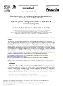
We determine the time-invariant parameters of the sliding mode controller developed in [8] by minimizing a specified performance objective under sliding mode control. Constraints in this minimization include satisfying limits on the control, restrictions on the parameters, and any dynamic restrictions on the state trajectory. The result is a nonlinear optimization problem similar to that posed in nonlinear predictive control except that the decision variables are the sliding mode control parameters as opposed to the actual control trajectory. There are a number of advantages to the proposed approach. Common performance objectives, such as minimum energy and minimum time, can easily be incorporated into the sliding mode control framework for underactuated systems. Physical constraints such as actuator saturation limits are easily implemented. Undesirable state trajectories can be eliminated through the use of dynamic state constraints in the optimization problem. If the resulting nonlinear optimization problem is feasible, the sliding mode controller will avoid these trajectories. If the optimization problem is infeasible, then the system is over specified and it is not possible to avoid the specified state trajectories. In this case, either the constraints on the control actuation, the constraints on the dynamic state trajectory, or both must be relaxed in order to obtain a feasible optimization problem. II. M ODEL USV S YSTEM In this work, the three degree of freedom (DOF) planar model of a surface vessel shown in Fig. 1 is considered. This model consists of surge, sway, and yaw motion with two propeller force inputs f 1 and f2 . The geometrical relationship between the inertial reference frame and the vessel-based body-fixed frame is defined in terms of velocities as x˙ = y˙ = θ˙ =
vx cos θ − vy sin θ vx sin θ + vy cos θ ω
(1)
where (x, y) denote the position of the center of mass, θ is the orientation angle of the vessel in the inertial reference frame, (vx , vy ) are the surge and sway velocity, respectively, and ω is the angular velocity of the vessel. In the body-fixed frame, the nonlinear equations of motion for a simplified model of the dynamics of a surface vessel, where motion in heave, roll, and pitch are neglected, are
2350
y
In this work, the controller is designed to track a target that may follow an arbitrary trajectory. In order to achieve tracking control, the desired state trajectory is defined by the nonlinear dynamic system
vx vy
x˙ i = −ai xi , ai > 0, i = 1, 2
where x1 = x − xt and x2 = y − yt are the state variables of the desired system trajectory, and x t and yt are the instantaneous target position. The result is a desired system trajectory that is exponentially stable, because of the constraint on a i , and that does not require knowledge of the future path of the target. The constants a i specify the speed of convergence in the respective coordinate directions. The desired state trajectories in the inertial reference frame are related to the corresponding surge and lateral velocities and accelerations as follows:
θ f1 f2 B x Fig. 1.
vxd vyd v˙ xd v˙ yd
Planar USV model schematic.
given by m11 v˙x − m22 vy ω + d1 vxα1 α m22 v˙y + m11 vx ω + d2 sgn(vy ) |vy | 2 m33 ω˙ + md vx vy + d3 sgn(ω) |ω|α3
= f = 0 = T
(2)
where mii are the mass and inertial parameters and m d = m22 − m11 > 0. The mii parameters include added mass contributions that represent hydraulic pressure forces and torque due to forced harmonic motion of the vessel which are proportional to acceleration. The hydrodynamic damping is modeled using a power law expression in Eq. (2). A more detailed discussion of the general spatial equations for surface vessels can be found in [9]. In this work, only forward vessel motion is considered, v x > 0, because the reverse motion dynamics are quite different. The surge control force f and the yaw control moment T are given in terms of the two propeller forces as f = f1 + f2 , T = (f2 − f1 )B/2
(5)
(3)
where B is the lateral distance between the propellers. III. S LIDING C ONTROL F ORMULATION In the sliding mode control approach, a set of asymptotically stable surfaces (S) are defined as functions of the tracking errors such that all system trajectories converge to these surfaces in finite time and slide along them until they reach the desired destination at their intersection. The reaching conditions are normally established by defining 1 T 2 S S as the Lyapunov function and ensuring that for surface i Si S˙i ≤ −ηi |Si | , ηi > 0, i = 1, 2 (4) where the value of the effort parameter η i determines how fast the trajectory will reach surface i. In the case of underactuated surface vessels, two surfaces are defined in terms of the surge and lateral velocities to determine the two control inputs.
= = = =
x˙ 1 cos θ + x˙ 2 sin θ −x˙ 1 sin θ + x˙ 2 cos θ x ¨1 cos θ + x¨2 sin θ − vyd ω −¨ x1 sin θ + x ¨2 cos θ − vxd ω
(6)
A. Surge Control Law The first sliding surface is a first-order exponentially stable surface defined in terms of the vessel’s surge motion tracking errors � t S1 = v˜x + λ1 v˜x (τ )dτ, λ1 > 0 (7) 0
where “ ˜ ” denotes the difference between the actual and desired values; i.e. v˜x = vx − vxd . Note that vxd is expressed in terms of x˙ 1 and x˙ 2 as shown in Eq. (6). A nominal surge control law for zero dynamics is determined by taking the time derivative of the surface and using the first equation of motion in Eq. (2) S˙ 1 = v˙ x + S˙ r1 = 0, S˙ r1 = −v˙ xd + λ1 v˜x fˆ = −m ˆ 22 vy ω +
dˆ1 vxα1
−m ˆ 11 S˙ r1
(8) (9)
where “ ˆ ” is used to indicate the estimated model parameters. The sliding mode control law is derived by subtracting a high-slope saturation function from the nominal control as in [10] f = fˆ − k1 sat(S1 /φ1 ) (10) � S1 /φ1 if |S1 | ≤ φ1 (11) sat(S1 /φ1 ) = sgn(S1 ) if |S1 | > φ1 where φ1 is a positive constant which defines a small boundary layer around the surface. The coefficient k1 is selected by first defining a Lyapunov candidate function similar to Eq. (4) that guarantees reaching the set {|S1 | ≤ φ1 } in finite time and remain inside this set thereafter: 1 (12) V1 = m11 S12 2 The time derivative of Eq. (12) can be derived as presented in [8] where the following reaching condition is achieved
2351
ˆ 11 η1 |S1 | V˙ 1 = m11 S1 S˙ 1 ≤ −m
(13)
if k1 is selected as
C. Stability Analysis
ˆ 11 η1 k1 = M22 |vy ω| + D1 vxα1 + M11 |S˙ r1 | + m
(14)
with the bounds for the model parameters, M ii and Di , defined as: |mii − m ˆ ii | ≤ Mii , |di − dˆi | ≤ Di , i = 1, 2, 3
(15)
B. Lateral Motion Control Law
The surge force and yaw moment control laws in Eqs. (10) and (17) are derived based on the reaching conditions in Eqs. (13) and (21), respectively. Integration of these reaching conditions verifies that the trajectory reaches the two �corresponding surfaces � � in �a finite time of less than S1 (0) S2 (0) m22 m33 m11 and respectively. Furthermore, m ˆ 11 η1 m ˆ 11 m ˆ 33 η2 the two surfaces in Eqs. (7) and (16) are asymptotically stable. Therefore the trajectory exponentially slides to the origin at the intersection of the two surfaces
The second sliding surface is a second-order exponentially stable surface defined in terms of the vessel’s lateral motion tracking errors S2 = v˜˙ y + 2λ2 v˜y + λ22
�
2
v˜y (τ )dτ, λ2 > 0
(16)
0
where v˜y = vy − vyd and v˜˙ y = v˙ y − v˙ yd . The yaw moment control law is derived for zero dynamics of the lateral motion using a high-slope saturation function in the same manner as the surge control law in Eq. (10) ˆ − k2 sat(S2 /φ2 )]/ˆb T = [h
(17)
�t v˜x → 0, 0 v˜x (τ )dτ → 0 �t v˜y → 0, 0 v˜y (τ )dτ → 0
and the kinematic relations in Eq. (1) guarantee trajectory tracking in the inertial reference frame. It can be shown that ω is BIBO (Bounded-Input-BoundedOutput) stable as follows. Define the Lyapunov candidate function 1 (25) V3 = m33 ω 2 2 and, using Eq. (2), the time derivative of V 3 may be written as:
where the nominal values of b and h are computed as: b = m22 vxd − m11 vx α h = b(md vx vy + d3 sgn(ω) |ω| 3 ) − (m11 vx ω + d2 sgn(vy ) |vy |
(19)
(26)
V˙ 3 < 0 if d3 |ω|α3 > |T − md vx vy |
(27)
In order to determine k 2 , another Lyapunov candidate function is defined 1 V2 = m22 m33 S22 2
(20)
(21)
if k2 is selected as ˆ k2 = β(H + m ˆ 22 m ˆ 33 η2 ) + (β − 1)|h|
1 α
3 d x y which determines an decreasing when |ω| > d3 upper bound for |ω|. Since T ,v x , and vy are bounded, the upper bound for ω remains bounded.
IV. O PTIMAL S LIDING M ODE PARAMETER S ELECTION
that guarantees reaching the set {|S 2 | ≤ φ2 } in finite time. This Lyapunov function yields the following reaching condition V˙ 2 = m22 m33 S2 S˙ 2 ≤ −m ˆ 22 m ˆ 33 η2 |S2 |
It follows from Eq. (25) that if V 3 is a decreasing function, then |ω| is also a decreasing function. From Eq. (27), V 3 is |T −m v v |
λ22 v˜y )
(22)
The closed-loop dynamic performance of the USV system under sliding mode control is a complex function of the effort (4), desired trajectory (5), and sliding surface (7,16) parameters. The effect of each of these parameters on the closed-loop response is often non-intuitive requiring either simulation or on-line tuning to achieve the desired control performance. In this work, a closed-loop optimal performance objective is used to determine these control parameter values. A general performance objective is constructed following the Bolza cost function in optimal control [11] without a terminal state penalty
with the bound for the uncertainty in h defined based on the parameter uncertainties defined in Eq. (15) |h − ˆ h| ≤ H
1+α3
= ω(T − md vx vy ) − d3 |ω|
)
+ m33 ω(f − d1 vxα1 + 2λ2 m11 vx + m22 vy ) α + 2λ2 m33 d2 sgn(vy ) + |vy | 2 + m22 m33 (vr + 2λ2 v˙ yd −
α V˙ 3 = ω [T − md vx vy − d3 sgn(ω) |ω| 3 ]
(18) α2 −1
(24)
(23)
and β is the bound based on the geometric mean of b [8].
min J =
{a,λ}
�
tf
L(x, u, t) dt
(28)
to
where x is the state of the system and u is the propeller forces determined by the sliding mode controller. This objective is minimized over the surface and trajectory parameters
2352
Path
Path 2.6
2.6 USV Target
2.2
2.2
2
2
1.8 1.6
1.8 1.6
1.4
1.4
1.2
1.2
1
1 0.5
1
1.5
USV Target
2.4
y (m)
y (m)
2.4
2
0.5
1
x (m)
Fig. 2.
USV Path using nominal parameters
Fig. 4.
Control Input 0.8
f
f1
1
0.6
0.6
f2
0.4
Force (N)
Force (N)
2
USV Path using minimum error optimization
Control Input 0.8
0.2 0 −0.2
f2
0.4 0.2 0 −0.2
−0.4 0
10
20
30
40
50
60
70
−0.4 0
80
Time (s)
Fig. 3.
�
Nominal parameter control input
x˙ = f (x, u, t) � � �−1 � � f1 1 1 f = −B/2 B/2 T f2
10
20
30
40
50
60
70
80
Time (s)
Fig. 5.
a and λ subject to the following constraints
u=
1.5
x (m)
(29)
the experimental system identification presented in [12]. The following input saturation constraints −0.4 ≤ fi (t) ≤ 0.8, i = 1, 2
(30)
g(x, u) ≤ 0
(31)
h(a, λ) ≤ 0
(32)
where f (x, u, t) is the dynamic equality constraint arising from the system equations, g(x, u) is a general inequality constraint on the states and control, and h(a, λ) is a general inequality constraint on the controller parameters arising from the surface and trajectory derivation. The control u is determined from the underactuated sliding mode control laws for f and T in Eqs. (10) and (17) that determine (f 1 , f2 ).
Minimum error optimization control input
(33)
are imposed based on physical constraints on the same experimental system. The sliding mode control parameter inequality constraints � � a h(a, λ) = − ≤ 0, i = 1, 2 (34) λi are applied such that the sliding mode parameters are strictly positive. In order to compare the performance of the optimized parameters, the nominal parameters
V. E XAMPLES In each of the following examples, the target follows a circular trajectory centered at (x=1m,y=2m) with a radius of 0.5 meters and constant angular velocity of 0.2rad/sec (a period of about 30s). The USV must approach and track the target from an initial position at (x=2m,y=1m). For simplicity, the values of a 1 and a2 defined in Eq. (5) are assumed to be equal; i.e. a 1 = a2 = a. The USV model parameters used in these examples are taken from
a λ1 λ2
= 0.4 = 1.5 = 4
are used where the resulting nominal USV path is shown in Fig. 2. The initial position of the target on the circular trajectory is indicated by the small circle in this figure. The nominal control action is shown in Fig. 3.
2353
TABLE I
Path
S OLUTIONS TO PARAMETER OPTIMIZATION
USV Target
2.5
Nominal 0.4 1.5 4.0 10.7 0.36
a λ1 λ2 J1 J2
y (m)
2
Error 1.4 6.1 14.7 4.0 1.6
Energy 0.22 0.90 6.81 18.25 0.22
1.5
B. Minimum Energy Objective The minimum energy objective determines the controller parameters that minimize the integral squared control effort cost function � tr (∆f12 + ∆f22 ) dt (37) min J2 =
1 0.5
1
1.5
2
x (m)
Fig. 6.
USV path using minimum energy optimization
{a,λ1 ,λ2 }
0
subject to the state constraint
Control Input 0.8
Force (N)
g(x) = d(tr ) − dtol ≤ 0
f1
0.6
f2
0.4 0.2 0 −0.2 −0.4 0
10
20
30
40
50
60
70
80
Time (s)
Fig. 7.
Minimum energy optimization control input
A. Minimum Tracking Error Objective The minimum tracking error objective determines the sliding mode controller parameters that minimize the integral squared error cost function � ∞ d2 dt (35) min J1 = {a,λ1 ,λ2 }
0
where d is defined as the distance between the center of mass of the USV and the target position (36) d = (x − xt )2 + (y − yt )2
The solution to the minimum error optimization is summarized in Table I. Fig. 4 presents the resulting USV path using the minimum tracking error optimal controller parameters and the control action is presented in Fig. 5. As shown in these figures, the speed of convergence to the target trajectory is much greater than the nominal case as a result of the increased control action where the objective function is reduced by more than 60%. The optimized sliding mode controller accelerates the USV toward the target using an approximately straight-line path (i.e. minimum distance) and then turns sharply to track the circular trajectory. The large control moves in the first ten seconds are necessary to generate the required turning moment and surge force for this path.
(38)
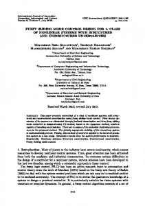
where ∆fi = fi − fiss , fiss is the steady-state control input required to follow the circular target trajectory, t r is the desired reach time, and d is defined in Eq. (36). The state constraint is implemented to force the USV to approach within a specified tolerance, d tol = 0.05m, of the target trajectory within a reach time of t r = 100s. Without this constraint, the minimum energy sliding mode controller approaches the target trajectory too slowly to be implemented in practice. The stable equilibrium trajectory for the experimental USV system considered in this work is circular, therefore there is a steady-state control input, f ss , that follows the desired trajectory. The solution to the minimum error optimization is also summarized in Table I. Fig. 6 presents the resulting USV path using the minimum energy optimal controller parameters and the control action is presented in Fig. 7. As shown in these figures, the speed of convergence to the target trajectory is much slower than the minimum tracking error and the nominal cases, but the energy objective function is reduced by an order of magnitude as shown in Fig. 8. The reduction in control action, however, results in a much more indirect path to the target. VI. C ONCLUSIONS In this work, an optimization based procedure to select the time-invariant parameters of the first- and second-order surfaces defined for sliding mode control of underactuated USV systems is developed and demonstrated on an experimental USV system model. The controller parameters obtained minimize a specified performance objective subject to dynamic constraints on the state and control action in addition to parameter constraints. The proposed method effectively identifies the parameter values that achieve the desired control performance for the closed-loop response of the system. As shown in Fig. 8, there is a significant improvement in the respective cost functions over the simulation time period for the examples presented in this work.
2354
Error (normalized)
Energy (normalized)
Objective Functions vs. Time 8 7 6 5 4 3 2 1 0
Nominal Minimum Error Minimum Energy
0
10
20
30
0
10
20
30
40
50
60
70
80
40
50
60
70
80
5 4 3 2 1 0
Time (s)
Fig. 8.
Comparison of objective function values
Future work in this area includes combining cost functions to reach a compromise between control energy and tracking error. The approach can also be extended to a closed-loop implementation where the control parameters are optimized on-line to produce time-varying surfaces. ACKNOWLEDGMENT Support for this work from the Office of Naval Research under ONR grant N00014-04-1-0642 and the Center for Nonlinear Dynamics and Control (CENDAC) at Villanova University is gratefully acknowledged. R EFERENCES [1] V. Utkin. Vaiable structure systems with sliding modes. IEEE Trans. Auto. Control, 11:212–222, 1977. [2] M. Salamci, M. Ozgoren, and S. Banks. Sliding mode control with optimal sliding surfaces for missile autopilot design. Journal of Guidance, Control, and Dynamics, 23:719–727, 2000. [3] B. Eksin, S. Tokat, M. Guzelkaya, and M. Soylemez. Design of a sliding mode controller with a nonlinear time-varying sliding surface. Transactions of the Institute of Measurement and Control, 25:145–162, 2003. [4] K. Kim and Y. Park. Sliding mode design via quadratic performance optimization with pole clustering constraint. SIAM Journal on Control and Optimization, 43:670–684, 2004. [5] M. Nikkhah, H. Ashrafiuon, and K. Muske. Optimal sliding mode control for underactuated systems. In Proceedings of the 2006 American Control Conference, pages 4688–4693, 2006. [6] H. Ashrafiuon and R. Erwin. Sliding mode control of underactuated multibody systems and its application to shape change control. International Journal of Control, DOI: 10.1080/00207170801910409, 2008. [7] D. Mayne, J. Rawlings, C. Rao, and P. Skocart. Constrained model predictive control: Stability and optimality. Automatica, 36:789–814, 2000. [8] H. Ashrafiuon, K. Muske, L. McNinch, and R. Soltan. Sliding mode tracking control of surface vessels. IEEE Trans. Indus. Elec., In press, 2008. [9] T. Fossen. Guidance and Control of Ocean Vehicles. Wiley, New York, 1994. [10] H. Khalil. Nonlinear Systems. Prentice-Hall, Upper Saddle River, NJ, 1996. [11] A. Bryson and Y Ho. Applied Optimal Control. Taylor & Francis, Levittown, PA, revised edition, 1975. [12] K. Muske, H. Ashrafiuon, R. McCloskey, G. Haas, and T. Flynn. Identification of a control oriented nonlinear dynamic USV model. In Proceedings of the 2008 American Control Conference, pages 562– 567, 2008.
2355