Computational Intelligence in Electrical Engineering, 7th year, No. 1, Spring 2016
1
Optimal Storage Scheduling in a Distribution Network Considering Charging of Plug-in Electric Vehicles Mahdi Sedghi1, Ehsan Pashajavid2, Masoud Aliakbar-Golkar3 1
PhD student, Faculty of Electrical Engineering, K. N. Toosi University of Technology, Tehran, Iran
[email protected] 2 PhD student, Faculty of Electrical Engineering, K. N. Toosi University of Technology, Tehran, Iran
[email protected] 3 Professor, Faculty of Electrical Engineering, K. N. Toosi University of Technology,Tehran, Iran
[email protected]
Abstract: This paper proposes an optimal scheduling for charge/discharge of centralized storage units within a distribution network. The storage units are used not only for peak cutting but also for decreasing energy not supplied due to failure events. The impact of plug-in electric vehicles (PEVs) charging on the optimal scheduling is taken into account as well. PEVs load demand is modeled using a stochastic approach based on the Monte Carlo simulation. Then, a Tabu search algorithm is utilized in order to fulfill the optimal scheduling of battery energy storages considering the extracted load demand of PEVs. Numerical studies on a typical distribution network show the impacts of various penetration levels of PEVs on the optimal scheduling issue. It should be mentioned that characteristics of the distribution network as well as the location of the stationary batteries affect the optimal scheduling.
Keywords: Distribution network, Plug-in electric vehicle, Storage optimization 1. Introduction1 The conventional passive distribution networks are changing to active ones. Active distribution networks are more flexible and reliable, because of the bidirectional electric power flow. The active networks contain new components such as distributed generators (DG) and storage units, and controllable loads. Batteries as storage units are new active components in modern distribution networks. Literature review shows that battery energy storage units can be used for several purposes such as frequency control [1], voltage sag mitigation [2, 3], voltage regulation [4, 5, 6], load following [7, 8], peak cutting [9-11], spinning reserve [12, 13] and dispatching of renewable sources [14-16]. As a matter of fact, scheduling of a storage unit is carried out according to its prespecified application. The scheduling should determine the power flow of battery in each hour and its direction (i.e. charge or discharge). Battery energy storage units can be scheduled by various methods. Some samples of strategy-based scheduling of batteries in a power system can be found in [15, 16, 18]. These methods are usually applied to the systems which include non1
Submission date: 23 , 07 , 2013 Acceptance date: 16 , 12 , 2014 Corresponding author: Mahdi Sedghi
dispatchable renewable energy resources (e.g. wind turbines). As a result, the power fluctuation is reduced and the owners of the renewable sources can bid in electricity market. A commonoperation-based scheduling for storage units is proposed in [6], where the distribution network operator is allowed to control the output of customers’ storage units during some specific time period. The customers usually utilize the battery units for peak cutting [6], while the network operators can control the same batteries to regulate the voltage level. This common operation is based on a contract between network operators and customers. Some other scheduling methods for battery units are based on optimization algorithms. In these methods, firstly a cost objective function is defined, and then, the battery units are scheduled optimally in order to minimize the objective function. In [19], [20] and [21], genetic algorithm, modified gravitational search algorithm and dynamic programming are employed in order to optimally schedule microgrids. The other new components which may affect scheduling of the centralized battery units are plug-in electric vehicles (PEVs). Recently, a great attention has been paid to PEVs as one of the hopeful and effective means in order to tackle the energy crisis and to alleviate the environmental problems [22, 23]. A considerably extensive
Optimal Storage Scheduling in a Distribution Network Considering ………….
amount of regulatory and technical efforts have been making to provide affordable PEVs. Therefore, a numerous number of PEVs will be undoubtedly on the road all around the world [24]. The possibility of bidirectional power transfer with the grid is one of the salient characteristics of PEVs. Actually, PEVs can absorb power from the grid when the state-of-charge (SOC) of the battery is low. On the other hand, it is possible for PEVs to inject power into the grid (V2G), especially, during the peak load hours [25]. In this case, the power of the PEVs, as dispersed mobile storage units, should be taken into account as a decision variable in scheduling problem. However, the PEVs are principally used for transportation and hence new limitations should be considered in optimal scheduling as well. Anyway, V2G requires a longer time to be practical [22]. In this paper, firstly, PEVs are modeled as uncoordinated load demand within domestic distribution networks and their load profile is estimated regarding home arrival time, daily traveled distance, home departure time, driving habits and road traffic conditions. Then, the centralized battery storage units are scheduled optimally in a distribution network considering the load profiles of PEVs integrated to the network. In the proposed scheduling which is fulfilled based on Tabu Search (TS) optimization algorithm the battery storage units are used for both peak cutting and reduction of energy not supplied due to failure events. In practice, the active distribution networks include not only storage units, but also DG sources. Hence, the dispatchable DG units are taken into account in this study to generalize the results. It should be noticed that the optimal scheduling depends on the configuration of a distribution network. The reminder of this paper is organized as follows. The optimal scheduling problem for battery storage units in distribution network is mathematically presented in section 2. Modeling of PEVs load for a domestic distribution network is shown in section 3. Section 4 describes the proposed optimal scheduling. Afterwards, case studies and numerical results are shown and discussed in section 5. Finally, conclusion remarks are given in section 6.
2. Problem statement The optimal storage scheduling problem consists of minimizing the cost objective function under technical constraints. An optimal scheduling should determine power flow of an energy storage and its direction (i.e. charge or discharge) in each hour of the specified period. The objective function is assumed to be the summation of the operation and reliability costs. The operation cost
2
of a distribution utility includes the cost of purchasing electrical energy from the upstream network via HV/MV substations, and the operation cost of DG units. Here, the reliability cost is the cost of energy not supplied because of failure events of HV/MV power transformers or MV feeder sections. Based on the formulation shown in [26], the objective function can be stated as follows: T
Min. F
OT j ,t Ct ] [ CiSS,t C DG t 1 iASS
(1)
jA DG
where CiSS , t is the cost of energy purchased via the i-th HV/MV substation at t-th hour, C DG j , t is operation cost of the j-th DG unit at t-th hour, CtOT is cost of the energy not supplied at t-th hour, ASS is set of all the HV/MV substations, ADG is set of all DG units and T is the period of scheduling (i.e. 24 hours). In (1), CiSS , t contains the power loss cost of distribution network and it is calculated by executing the backward/forward sweep load flow in presence of DG and battery units. In optimal solution for the scheduling problem, the maximum capacity of the equipments should not be exceeded; the voltage magnitude of the all nodes should be kept within allowed boundary and demanded energy should be supplied in normal conditions of the network. The technical constraints are given in (2)-(4) which are based on the formulation presented in [27]. u u Smin Stu Smax , u A EQ , t 1,2,...,T
(2)
Vmin Vi,t Vmax, i A N , t 1,2,...,T
(3)
S
iA SS
SS i ,t
S
jA DG
, t 1,2,...,T
DG j ,t
S
k A ST
ST k ,t
S
lA LD
LD l ,t
StLOSS
(4)
where Stu is the power of equipment u at t-th u u hour, S min and S max are the allowed minimum and maximum power of equipment u, Vi , t is the voltage magnitude in i-th node of the network at tth hour, Vmin and Vmax are the allowed minimum
and maximum voltage magnitudes, SiSS , t is the power of the i-th HV/MV substation at t-th hour, S DG j , t is the generated power of j-th DG unit at t-th hour, S kST, t is the charge power of the k-th storage unit at t-th hour, SlLD , t is the total load (containing
Computational Intelligence in Electrical Engineering, 7th year, No. 1, Spring 2016
PEVs demand) power of the l-th node at t-th hour, and StLOSS is the total power loss in distribution network at t-th hour. A EQ is set of all the equipments, A N is set of all the nodes, AST is set of all the storage units and A LD is set of all the load nodes. In (4),
S kST, t
is a negative value during
discharge period. Moreover, some especial constraints should be satisfied for battery storage units as follows. 1. Discharging power of the batteries is a function of the stored energy in previous hours, battery efficiency and pulse power capability of the battery. 2. The batteries can be charged and discharged only once in each day because of lifetime limitations and reducing investment cost. 3. The batteries should not be discharged completely, because of the technical constraints.
3. PEVs load demand In this section, load demand due to PEVs in a domestic medium voltage distribution network is modeled and their absorbed power profile through distribution transformers is estimated. The most effective factors on the load demand of PEVs are home arrival time, daily traveled distance, home departure time, driving habits and road traffic conditions. Moreover, battery capacity of PEVs and efficiency of the battery chargers can be noted as well. Most of the mentioned factors, due to the related uncertainties are not deterministic. Hence, a stochastic method based on the Monte Carlo simulation is employed to extract the hourly aggregated load demand of PEVs.
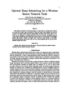
3.1. Datasets of the internal combustion engines (ICE) vehicles The employed datasets in the modeling algorithm have been gathered using questionnaires filled-out by the randomly selected owners of the commuter light duty ICE vehicles in Tehran. As observable in Fig. 1, the datasets include home arrival time (at), daily traveled distance (trd) and home departure time (dt) of the vehicles during weekdays. To generate random samples required in the Monte Carlo simulation, it is essential to fit appropriate probability density functions (pdfs) to the three mentioned random variables (RVs). The Weibull pdf (fdt(t)) is suggested to be fitted to the departure time RV as below [28]:
3
t ( 1) t ( ) exp ( ) , t 0 (5) To model the daily traveled distance a type III Generalized expected value (Gev) pdf (6) is derived. f d t (t )
1
f trd (d )
d trd (1 k tr ) d (1 ktrd )
1
tr
tr
d
d
1 d trd k tr exp (1 ktrd ) d trd
(6)
This formulation is adopted from [28]. A type III Generalized expected value (Gev) pdf (7) is fitted to the home arrival time RV as well. f a (t ) t
1 t a (1 k ) (1 k a )
1
a
t
t
t
a
at
t
1 t a k exp (1 k a ) a t
(7)
at
t
t
[‘The results are illustrated in Fig (1) It is clear that the fitted non-Gaussian pdfs provide a better approximation of the original datasets. The parameters of the fitted pdfs are given in Table (1).
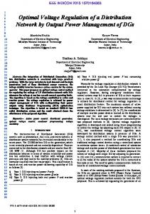
3.2. Modeling methodology 3.2.1. The employed algorithm It is assumed that only the home charging is available and the PEVs are plugging into the grid as soon as their arrival. Fig (2) illustrates the overall procedure of the approach. Regarding the extracted pdfs, the random samples of at (an), trd (trn) and dt (dn) are generated. The available charging time (tavi) for each of the PEVs is calculated by subtracting the departure time of the next day (dn+1) from the arrival time of today (an). The PEV battery capacity (Capbat), initial state-of-charge of the battery (SOCinit), power rating (Prat) and efficiency (Cchr) of the PEV battery chargers determine the necessary time (tfull) to fully charge the battery. In case tfull would be less than tavi, the complete charging of the PEV battery can be accomplished. In any other way, it would be impossible to fully charge the battery.
(a) Probability Density
Computational Intelligence in Electrical Engineering, 7th year, No. 1, Spring 2016
Data Normal pdf
1
Weibull pdf
0.5
0
6
6.5
7 7.5 Departure time (hour)
(b) Probability Density
0.06
8
8.5
Data Normal pdf Gev pdf
0.05 0.04 0.03 0.02 0.01 0
0
10
20 30 Travelled distance (km)
0.6
(c) Probability Density
4
40
50
Data Normal pdf Gev pdf
0.4
0.2
0 15
16
17
18 Arrival time (hour)
19
20
21
Fig (1): The data and pdfs of (a) home departure time dt, (b) daily travelled distance trd and (c) home arrival time at. Table (1): The parameters of the fitted pdfs
Datasets
The Normal pdf
The suggested pdf
dt
Nd t 7.48436 Nd t 0.43178
7.67454 21.3812
trd
at
Ntrd 21.4150 Ntrd 8.58711
Nat 17.7170 Nat 1.01385
3.2.2. The PEV battery initial SOC The SOCinit is determined based on the daily traveled distances. Regarding the fact that tavi in home charging is usually bigger than tfull, it is rational to assume that the battery SOC are 100% at the departure time of the PEVs. Hence, the SOCinit of the PEV can be derived as follows: trdn SOC initn 100 100 (8) C eff Capbat where Ceff is the efficiency coefficient of the PEV during driving which depends on the driving patterns and traffic conditions as well as driver
ktrd 0.052368
trd 17.6568 trd 7.1222 kat 0.060798
at 17.2700 at 0.84832
efficiency of the electric motors. Considering IN as the iteration number of the Monte Carlo simulation, the explained procedure is carried out for IN times in order to derive the distribution of the aggregated power consumption of a PEV within each hour. Afterwards, the expected values of the hourly load demand of the PEV can be calculated. Eventually, demand profile of the PEV is estimated by employing the extracted expected values. This demand profile affects the optimal scheduling, and it is considered in optimization approach.
Computational Intelligence in Electrical Engineering, 7th year, No. 1, Spring 2016
Start Data Gathering (at, trd, dt) Fitting appropriate pdfs to RVs n=1 Random generation (an, trdn, dn) SOCinitn extraction
No
tavin >= tfulln
tChn=tavin
OC. j .[PjOUT (t ) PjRDG PjRST (t )].t
(9)
Yes tChn=tfulln
occurring the j-th failure event, PjOUT (t ) is the disconnected load power due to j-th failure event at time t, PjRDG is the restored power by all DG
SOCt=SOCt-1+(100Prat.Cchr)/Capbat
units after j-th failure event, PjRST (t ) is the
No
restored power by all storage units at time t (after j-th failure event), t is the equipments repair/replacement time and A EV is set of all the possible failure events in distribution network. In (9), PjRST (t ) is a function of the SOC of the
Yes
centralized batteries at time t, pulse power capability of the batteries, power factor of load and configuration of the network after switching process.
t=t+1
Yes n=n+1 n tChn
the DG sources, storage units can restore the loads regarding their previous charge/discharge trajectory and their state-of-charge. As a result, for every probable failure event, the SOC of centralized battery units should be estimated. This state-of-charge should be optimized in each hour, considering the possibility of all the failure events in distribution network. The cost of energy not supplied in (1) can be stated as follows. jA EV
tavi = dn - an tfulln=(100-SOCinitn).Capbat /(100Prat.Cchr)
5
No Profile derivation End
Fig (2): Flowchart of the proposed approach for PEV demand profile estimation
4. Proposed optimal scheduling In this section the proposed multiobjective scheduling of centralized stationary battery units is presented. This scheduling is optimized using Tabu search algorithm.
4.1. Multiobjective scheduling In order to maximize the benefits of the centralized battery units, they are utilized for two objectives. As the first objective, they are scheduled for peak cutting to reduce the cost of electrical energy purchased by the distribution utility and also, to reduce the power loss in the network. As the second objective, if a failure event occurs for an equipment (i.e. a power transformer or feeder section), the failed equipment is disconnected from the other equipments by normally closed switches. Then, the disconnected loads are restored using DG and storage units, if it is possible from technical points of view. Unlike
4.2. Tabu search (TS) algorithm To minimize the objective function given by (1), a heuristic method can be used. In this paper, the heuristic TS algorithm is applied. TS algorithm is based on iterative local search along a trajectory. Starting from a feasible solution as the current solution which satisfies the constraints, some neighbor solutions are selected. The objective functions of the selected neighbors are calculated using (1). Afterwards, the best neighbor solution is selected as the new current solution to continue the local search. This process is iterated until a termination criterion is satisfied. To prevent cycling, a Tabu list is used in TS. More details about TS can be found in [29]. The TS algorithm is applied in this paper due to its fast convergence. The following algorithm is proposed in order to generate a new neighbor solution of the current solution in TS. Step 1) If mST rand , go to step 5. Step 2) Select the k-th storage unit among all storage units, randomly. Step 3) Select the t1-th and t2-th hours randomly that 0 t1 24 , 0 t2 24 and t1 t2 .
Optimal Storage Scheduling in a Distribution Network Considering ………….
Step 4) Make
, P rand S kST ,t1
, NEW SkST SkST ,t1 P ,t
Table (2): The simulation parameters for PEV demand extraction
1
, NEW SkST , and SkST ,t 2 P , and stop. ,t
Parameter IN Prat Capbat Ceff Cchr
2
Step 5) Select the j-th DG unit among all DG units, randomly. Step 6) Select the t1-th hour randomly that 0 t1 24 . , NEW DG , Step 7) Make S DG S DG j ,t 2 (rand 0.5) S j ,t j ,t 1
1
Value 10000 3 (kW) 20 (kWh) 2 (km/kWh) 0.9
1
and stop. where, 0 mST 1 is the searching rate for centralized storage units and rand is a random , NEW number within (0,1). S kST,t and SkST are the ,t
Departure time (hour)
8.5
power consumption of the k-th centralized storage unit at t-th hour, in the current solution and new neighbor solution, respectively. S DG j ,t and , NEW S DG j ,t
6
8 7.5 7 6.5 6
are the generated power of j-th DG
5.5
source at t-th hour, in the current solution and new , NEW neighbor solution, respectively. S kST, t and SkST ,t
5
16
18
20
22
24
Arrival time (hour)
Fig (3): PEVs battery initial SOC
may be positive or negative.
percentage of the charging/discharging power at time t 1, that is moved from the charging/discharging power at time t1 to the charging/discharging power at time t2. In this case, maximum SOC of the centralized batteries in the new neighbor solution should not be different from the one of the current solution. This maximum SOC is equal to the rated capacity of the centralized battery units.
5. Numerical studies 5.1. PEV demand extraction To estimate the load demand profile of the PEVs, the procedure explained in section 3 is repeated 10000 times to deal with the related uncertainties. The simulation parameters can be found in Table (2). Fig (3) presents distribution of the randomly generated samples (the synthetic data) of the arrival times and departure times. Similarly, scatter plots related to the traveled distances can be provided. 5.1.1. The PEVs battery initial SOC To derive the PEVs battery initial SOC (SOCinit) the mentioned scenario is employed. The SOCinit is determined based on the daily traveled distances. According to (8), the SOCinitn depends on the traveled distance (trdn), the battery capacity (Capbat) and the efficiency coefficient of PEVs during driving (Ceff). The distribution of the synthetic initial SOCs of the PEVs is shown in Fig (4).
3000
Number of samples
1
2500 2000 1500 1000 500 0 30
40
50
60
70
80
90
100
SOC
init
Fig (4): PEVs battery initial SOC.
5.1.2. The aggregated power consumption According to Fig (2), the procedure is repeated for 10000 times in order to derive the distribution of the aggregated power consumption within each hour. The expected values of the hourly load demand of the PEV are presented in Fig. 5 which can be referred as the demand profile of the vehicle. 3000
Load demand (W)
In step 4, the value of P ( P S kST ) is a ,t
2500 2000 1500 1000 500 0 14:00
16:00
18:00
20:00
22:00
0:00
2:00
4:00
Hours
Fig (5): Demand profile of a PEV
5.2. Optimal scheduling In order to test the proposed scheduling for centralized storage units, a typical 33-kV distribution network is considered. This typical
6:00
Computational Intelligence in Electrical Engineering, 7th year, No. 1, Spring 2016
network is a modified configuration of the grid presented in [30]. Network characteristics and parameters are shown in Table 3 and Table 4. The outage cost data is given in Table 5. Market price and load level profile are shown in Fig (6) This profile belongs to a typical weekday in summer. The market price is shown considering the three-level electricity price in Iran. The pulse power capability of a battery is presented in Fig (7) This figure is applied for
7
can not provide 130 (%) of its rated power within an interval which is larger than 4 hours. In the following sections, the numerical studies are presented in two cases. Table (4): Parameters of the typical distribution network Parameter Value Resistance of feeders (Ω/km) 0.1738 Reactance of feeders (Ω/km) 0.2819 Capacity of feeders (A) 213 Feeders failure rate (f/km-yr) 0.1087 Feeders repair/replacement time (hr) 4 HV/MV transformer failure rate (f/yr) 0.0325 HV/MV transformer repair/replacement 8 time (hr) Centralized battery capacity (kWh) 2000 Centralized battery efficiency (%) 75 Minimum depth of discharge (kWh) 200 DG capacity (kW) 400 Load power factor 0.9 DG power factor 1 Centralized battery power factor 1 Peak demand in each node, without PEVs 160 (kW)
Table (3): Configuration properties of the typical distribution network Feeder Sending Receiving Length no. node node (m) 1 1 10 202 2 6 7 818 3 10 6 650 4 10 14 430 5 10 18 840 6 21 13 820 7 14 23 486 8 18 21 574 9 8 2 76 10 9 3 1820 11 5 4 940 12 23 5 641 13 7 8 687 14 8 9 2057 15 10 17 430 16 10 20 697 17 21 11 639 18 23 12 679 19 18 15 571 20 20 16 502 21 21 19 555 22 21 22 526
Table (5): Outage cost function Interruption duration Outage cost (min) ($/kW) 60 0.482 240 4.914 480 15.69
5.2.1. Case 1 As the first case, it is supposed that there is a centralized battery storage unit in node number 3. This node is selected regarding some initial computations. If PEVs are not considered as load demands the optimal scheduling for charge/discharge of centralized battery
calculating discharge power of a battery. It indicates a technical constraint for battery units. For example, as can be seen, the battery system
Load level (%), Electricity price ($/MWh)
110
Load level Electricity price
100 90 80 70 60 50 40 30 20 10 0
2
4
6
8
10
12
14
16
18
20
Hours
Fig (6): Market price and load level profile for case studies
22
24
Optimal Storage Scheduling in a Distribution Network Considering ………….
8
Fig(7): Discharge pulse power capability of batteries [31]
units is obtained using TS algorithm as shown in Fig (8) In this case, the battery unit is charged within 1-5 a.m. and it is discharged during 13-15 and 19-24. The charging power within 1-3 a.m. is higher compared to 3-6 interval, because the battery should be charged faster to support the loads against failure events. On the other hand, a fast charging increases the power loss in the network. Considering Fig (6), within 20-23 the electricity price is higher, but battery unit is discharged not only within 20-24, but also during 13-15 because of high demand due to air conditioning loads. Assuming 100% penetration level of PEVs, optimal scheduling of the centralized battery units can be depicted as Fig (9) As it can be seen, the battery units are discharged only during 17-24 because of the PEVs extracted load profile Fig (5). Opposing to Fig (8), charging power of the centralized battery is higher during 3-5 in Fig (9) because a portion of PEVs are charged within 1-2 a.m. The power loss will be more if the centralized
battery is charged faster. 5.2.2. Case 2 As case 2, it is supposed that there are two dispatchable DG sources in nodes 11 and 21 and two battery units are installed in nodes 2 and 3. These nodes are selected regarding some initial computations. If no PEVs are connected to the grid, the optimal charge/discharge scheduling of the two centralized battery units is according to Fig (10). The battery unit at node number 3 is discharged only within 17-24, but the one at node number 2 is discharged during 11-15 and 20-23. So discharging one of the battery units is enough for peak cutting during 11-15. On the other hand, both battery units are charged within 1-6; however, their charging power follow different curves in order to reduce the power loss in the feeders and transformers. The differences between the charge/discharge profiles of these battery units are due to their locations in the distribution network.
Power (kW), State-of-charge (kWh)
2000
State-of-charge Power
1500
1000
500
0
-500
5
10
15
20
Hours
Fig (8): Optimal scheduling for centralized battery unit in case 1 without PEVs
Computational Intelligence in Electrical Engineering, 7th year, No. 1, Spring 2016
Power (kW), State-of-charge (kWh)
2000
9
State-of-charge Power
1500
1000
500
0
-500
5
10
15
20
Hours
Fig (9): Optimal scheduling for centralized battery unit in case 1 with PEVs
Power (kW), State-of-charge (kWh)
2000
1500
Power (node 3) Power (node 2) State-of-charge (node 2) State-of-charge (node 3)
1000
500
0
-500
5
10
15
20
Hours
Fig (10): Optimal scheduling for centralized battery units in case 2 without PEVs
If the PEVs are connected to the network with a penetration level of 25%, then the optimal scheduling of centralized batteries is according to Fig. 11. Accordingly, the battery unit at node number 2 is discharged only during 17-24, and the other one at node number 3 is discharged within 16-19 and 20-24 regarding PEVs demand profile. If the penetration of the PEVs increases to 50%, then both centralized battery units are discharged only during 17-24, as shown in Fig. 12. However, charging intervals of the centralized battery units is the same for 25% and 50% penetration level of PEVs. Comparing Fig (12) with Fig (10) shows that the average SOC of centralized batteries in Fig (12) is more than the one in Fig (10), e.g. within 15-17. As a result, the restored load by battery units, after probable failure events, in Fig (12) is more than the one in
Fig (10). If the PEVs are supposed to be as new customers, the Average System Curtailment Index (ASCI) is 163.6773 (kWh/customer) in each day for 50% penetration level of PEVs. While, without PEVs, the ASCI is more (i.e. 220.5864 (kWh/customer)) in each day for optimal scheduling of system. Here, the ASCI is obtained from the following equation [32]: nL
ASCI
Li .U i i 1
(10)
N where Li is the average load connected to load point i, Ui is the average outage time, N is the total number of customers served, and nL denotes the number of all the load nodes.
Optimal Storage Scheduling in a Distribution Network Considering ………….
10
Power (kW), State-of-charge (kWh)
2000
1500
Power (node 3) Power (node 2) State-of-charge (node 2) State-of-charge (node 3)
1000
500
0
-500
5
10
15
20
Hours
Fig (11): Optimal scheduling for centralized battery units in case 2 with 25% penetration of PEVs
Power (kW), State-of-charge (kWh)
2000
Power (node 2) Power (node 3) State-of-charge (node 2) State-of-charge (node 3)
1500
1000
500
0
-500
5
10
15
20
Hours
Fig (12): Optimal scheduling for centralized battery units in case 2 with 50% penetration of PEVs
6. Conclusions In this paper, a short-term optimal scheduling for stationary centralized battery units in distribution network has been proposed. The battery units have been scheduled not only for peak cutting, but also for diminishing energy not supplied due to failure events. This paper mainly consideres the impact of PEVs charging on the optimal scheduling of centralized batteries in a distribution network. Firstly, the charging load demand of PEVs has been modeled using a stochastic method based on Monte Carlo simulation. Then, the battery units have been scheduled optimally by TS algorithm, in the presence of the PEVs connected to the distribution network. Numerical studies on a typical distribution network showed that PEVs can change the optimal charge/discharge scheduling of centralized battery units. In a summer weekday, the peak load usually is within midday times, but the estimated load profile of PEVs is commonly higher in afternoon. As a result, PEVs (as new components in distribution networks) postpone discharging of centralized batteries to later hours in a day, regarding the penetration level of PEVs. As a phenomenal effect, this made the system more reliable considering ASCI of the distribution
network. Moreover, PEVs influenced the charging power of the centralized batteries partly because of increasing power loss in feeder sections and transformers. Generally, the proposed optimal scheduling, in all cases, dependes on the configuration of the distribution network as well as the location of the battery energy storage units.
References [1] Mercier P., Cherkaoui R. and Oudalov A.,
"Optimizing a battery energy storage system for frequency control application in an isolated power system", IEEE Trans. on Power Systems., Vol. 24, pp. 1469–1477, 2009. [2] Bhatia RS., Jain SP., Jain DK. and Singh B., "Battery energy storage system for power conditioning of renewable energy sources", Int. Conf. on Power Electronics and Drives Systems, pp. 501–506, 2005. [3] Wang XY., Vilathgamuwa DM. and Choi SS., "Buffer scheme with battery energy storage capability for enhancement of network transient stability and load ride-through", Journal of Power Sources, Vol. 179, pp. 819– 829, 2008. [4] Bhatia RS., Jain SP., Jain DK. and Singh B.,
Computational Intelligence in Electrical Engineering, 7th year, No. 1, Spring 2016
"Battery energy storage system for power conditioning of renewable energy sources", Int. Conf. on Power Electronics and Drives Systems, pp. 501–506, 2005. [5] Barrado JA., Gri nَ R. and Valderrama-Blavi H., "Power-quality improvement of a standalone induction generator using a STATCOM with battery energy storage system", IEEE Trans. on Power Delivery, Vol. 25, pp. 2734– 2741, 2010. [6] H. Sugihara, K. Yokoyama, O. Saeki, K. Tsuji and T. Funaki, "Economic and efficient voltage management using customer-owned energy storage systems in a distribution network with high penetration of photovoltaic systems", IEEE Trans. on Power Systems, Vol. 28, pp. 102–111, 2012. [7] Hida Y., Yokoyama R., Shimizukawa J., Iba K., Tanaka K. and Seki T., "Load following operation of NAS battery by setting statistic margins to avoid risks", IEEE Power and Energy Society General Meeting, 2010. [8] Lee T-Y., "Operating schedule of battery energy storage system in a time-of-use rate industrial user with wind turbine generators: a multipass iteration particle swarm optimization approach", IEEE Trans. on Energy Conversion, Vol. 22, pp.774–782, 2007. [9] Dufo-Lَpez R., Bernal-Agustin JL. and Dominguez-Navarro JA., "Generation management using batteries in wind farms: economical and technical analysis for Spain", Energy Policy, Vol. 37, pp. 126–139, 2009. [10] S. Grillo, M. Marinelli, S. Massucco and F. Silvestro, "Optimal management strategy of a battery-based storage system to improve renewable energy integration in distribution networks", IEEE Trans. on Smart Grid, Vol. 3, pp. 950–958, 2012. [11] Hu W., Chen Z. and Bak-Jensen B., "Optimal operation strategy of battery energy storage system to real-time electricity price in Denmark", IEEE Power and Energy Society General Meeting, 2010. [12] Lee D-J. and Wang L., "Small-signal stability analysis of an autonomous hybrid renewable energy power generation/energy storage system part I: time-domain simulations", IEEE Trans. on Energy Conversion,Vol. 23, pp. 311–320, 2008. [13] Parker CD., "Lead-acid battery energystorage systems for electricity supply networks", Journal of Power Sources, Vol. 100, pp. 18–28, 2001. [14] S. Teleke, ME. Baran, S. Bhattacharya and AQ. Huang, "Rule-based control of battery energy storage for dispatching intermittent renewable sources", IEEE Trans. on
11
Sustainable Energy, Vol. 1, pp. 117–124, 2010. [15] Q. Li, SS. Choi, Y. Yuan and DL. Yao, "On the determination of battery energy storage capacity and short-term power dispatch of a wind farm", IEEE Trans. on Sustainable Enrgy, Vol. 2, pp. 148–158, 2011. [16] DL. Yao, SS. Choi, KJ. Tseng and TT. Lie, "Determination of short-term power dispatch schedule for a wind farm incorporated with dual-battery energy storage scheme", IEEE Trans. on Sustianable Energy, Vol. 3, pp. 74– 84, 2012. [17] S. Teleke, ME. Baran, AQ. Huang, S. Bhattacharya and L. Anderson, "Control strategies for battery energy storage for wind farm dispatching", IEEE Trans. on Energy Conversion, Vol. 24, pp. 725-732, 2009. [18] S. Teleke, ME. Baran, S. Bhattacharya and AQ. Huang, "Rule-based control of battery energy storage for dispatching intermittent renewable sources", IEEE Trans. on Sustainable Energy, Vol. 1, pp. 117–124, 2010. [19] C. Chen, S. Duan, T. Cai, B. Liu and G. Hu, "Smart energy management system for optimal microgrid economic operation", IET Renew. Power Gener., Vol. 5, pp. 258–267, 2011. [20] T. Niknam, F. Golestaneh and A. Malekpour, "Probabilistic energy and operation management of a microgrid containing wind/photovoltaic/fuel cell generation and energy storage devices based on point estimate method and self-adaptive gravitational search algorithm", Energy, Vol. 43, pp. 427–437, 2012. [21] S. Grillo, M. Marinelli, S. Massucco and F. Silvestro, "Optimal management strategy of a battery-based storage system to improve renewable energy integration in distribution networks", IEEE Trans. on Smart Grid, Vol. 3, pp. 950–958, 2012. [22] W. Su, H. Rahimi Eichi, W. Zeng and M. Chow, "A survey on the electrification of transportation in a smart grid environment", IEEE Trans. on Industrial Informatics, Vol. 8, pp. 1–10, 2012. [23] MA. Golkar and E. Pashajavid, "Analytical assessment of mutual impacts between PHEVs and power grid", 21st Int. Conf. on Electricity Distribution (CIRED), Frankfurt, 6–9 June 2011. [24] AY. Saber and G.K. Venayagamoorthy, "One million plug-in electric vehicles on the road by 2015", Proceeding of the 12th International Conf. on Intelligent Transportation Systems, 2009, pp. 141–147. [25] JR. Pillai and B. Bak-Jensen, "Integration of
Optimal Storage Scheduling in a Distribution Network Considering ………….
vehicle-to-grid in the western Danish power system", IEEE Trans. on Sustainable Energy, Vol. 2, No. 1, pp. 1949–3029, Sep. 2010. [26] H. Falaghi, C. Singh, MR. Haghifam and M. Ramezani, "DG integrated multistage distribution system expansion planning", Electrical Power and Energy Systems, Vol. 33, pp. 1489–1497, 2011. [27] M. Sedghi, M. Aliakbar-Golkar and MR. Haghifam, "Distribution network expansion considering distributed generation and storage units using modified PSO algorithm", Electrical Power and Energy Systems, Vol. 52, pp. 221–230, 2013. [28] R. Kollu1, SR. Rayapudi1, SVL. Narasimham and KM. Pakkurthi, "Mixture probability distribution functions to model wind speed distributions", International Journal of Energy and Environmental Engineering, Vol. 3, pp. 1– 10, 2012. [29] EK. Burke and G. Kendall, "Search methodologies: introductory tutorials in optimization and decision support techniques", New York: Springer-Verlag, 2005. [30] JF. Gomez, HM. Khodr, PM. De Oliveira, L. Ocque, JM. Yusta, R. Villasana and AJ. Urdaneta, "Ant colony system algorithm for the planning of primary distribution circuits", IEEE Trans. on Power Systems, Vol. 19, pp. 996–1004, 2004. [31] E. Naderi, I. Kiaei and MR. Haghifam, "NaS technology allocation for improving reliability of DG-enhanced distribution networks", IEEE 11th Int. Conf. on Probabilisstic Methods Applied to Power Systems (PMAPS), Singapore, pp. 14–17 June, 2010. [32] R. Billinton and RN. Allan, "Reliability evaluation of power systems", New York and London: Plenum Press, 1996.
12