March 15, 2000 / Vol. 25, No. 6 / OPTICS LETTERS
363
Optimal synthesis of three-dimensional complex amplitude distributions Gal Shabtay, Zeev Zalevsky, Uriel Levy, and David Mendlovic Faculty of Engineering, Tel Aviv University, 69978 Tel Aviv, Israel Received October 13, 1999 The synthesis of three-dimensional (3-D) light distributions is important for many applications. For example, in scanning applications it is preferable that the scanning beam preserve its characteristics over a large distance to yield elongated scanning range. It is evident that any 3-D light distribution must satisfy the wave equation or, in second-order approximation, the Fresnel diffraction formula. Thus many desirable 3-D light distributions may not be realizable. We propose a single optical element (OE) that synthesizes a physical beam within a certain 3-D region. The OE provides the optimal physical beam in comparison with a desired one in the sense of minimal mean-square error. 2000 Optical Society of America OCIS code: 140.3300.
The spatial distribution of a laser beam is an important property when one is characterizing a laser light source. Often the spatial profile is not suited to the application that it needs to fulf ill. In these cases beam shaping is needed, as described in Ref. 1 and by many other authors. Optical information processing and interferometry usually required near-f ield, uniform phase and intensity beam shaping. Such beam shaping, which requires control of the complex amplitude prof ile, is usually done by two phase elements separated in space.2,3 Beam shaping in the far field usually requires the synthesis of a complex amplitude whose Fourier transform is the desired function. In some applications the phase of the far-f ield distribution is unimportant. A popular method for determining the optimal phase distribution is given by the Gerchberg –Saxton algorithm for iterative phase retrieval.4 Three-dimensional beam shaping has been studied intensively in the context of generation of nondiffracted light beams.5 – 7 In this Letter an analytic method for optimal synthesis of 3-D complex amplitude distributions is described. Because light travels according to the wave equation, not all desired 3-D complex amplitudes are feasible. For those nonphysical distributions the proposed algorithm will result in the closest 3-D distribution in the sense of minimum mean-square error (MMSE). The task of finding the complex amplitude, rather than intensity, optimal distribution has been undertaken because of the possibility of achieving a unique analytical expression, whereas the optimization of a 3-D intensity distribution is not unique. Mathematical analysis of the proposed method and computer simulations to demonstrate its performances are provided in what follows. Let us consider a 3-D region 共ᑬ兲 that is finite along the z axis and infinite along the other Cartesian axes 共x, y兲, in which it is desirable to obtain a complex amplitude of the form ud 共x, y, z兲. If the specified ud 共x, y, z兲 satisf ies the wave equation, one may generate one specif ic cross section of it, e.g., ud 共x, y, z0 兲, and the problem is solved with MMSE 苷 0. If ud 共x, y, z兲 does not satisfy the wave equation or the Fresnel diffraction in0146-9592/00/060363-03$15.00/0
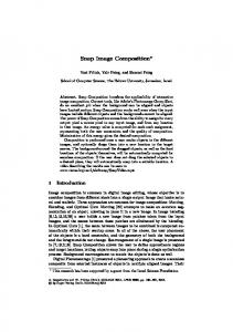
tegral, the goal is to synthesize the closest physical complex amplitude by the use of an optical element (OE) in the optical setup described in Fig. 1. According to the MMSE criterion, the OE, f 共x, y兲, should be determined such that the following error metric will be minimized: Z `Z ` Z j f 共x, y兲 ≠ h共x, y; z兲 e苷 2`
2`Dz
2 ud 共x, y, z兲j2 dzdxdy ,
(1)
where ≠ denotes a two-dimensional convolution operation and h共x, y; z兲 denotes the Fresnel kernel. To determine f 共x, y兲 that minimizes e of Eq. (1) it is easier to view the problem in the Fourier plane by making use of Parseval’s theorem: Z `Z ` Z ˜ e苷 j f˜ 共u, v兲h共u, v; z兲 2`
2`Dz
2 u˜ d 共u, v, z兲j2 dzdudv ,
(2)
˜ where f˜ 共u, v兲, h共u, v; z兲, and u˜ d 共u, v, z兲 represent the two-dimensional Fourier transforms of f 共x, y兲, h共x, y; z兲, and ud 共x, y, z兲, respectively. f˜ 共u, v兲 may be written as f˜ 共u, v兲 苷 f˜R 共u, v兲 1 if˜1 共u, v兲, where both f˜R 共u, v兲 and f˜1 共u, v兲 are real-valued functions. To find these functions, which minimize e, we use the method of calculus of variations. According to this method the functions f˜R 共u, v兲 and f˜1 共u, v兲 satisfy the following equations: ≠ Z ˜ j共 f˜R 共u, v兲 1 if˜1 共u, v兲h共u, v; z兲 ≠f˜R Dz 2 u˜ d 共u, v, z兲j2 dz 苷 0 ,
Fig. 1. The optical setup. 2000 Optical Society of America
(3)
364
OPTICS LETTERS / Vol. 25, No. 6 / March 15, 2000
≠ Z ˜ j共 f˜R 共u, v兲 1 if˜1 共u, v兲h共u, v; z兲 ≠f˜1 Dz 2 u˜ d 共u, v, z兲j2 dz 苷 0 .
(4)
Hence from Eqs. (3) and (4) one obtains Z Dz
˜ ˜ h共u, v; z兲 关 f˜ 共u, v兲h共u, v; z兲 2 u˜ d 共u, v, z兲兴ⴱ dz 1 Z Dz
˜ ⴱ 共u, v; z兲 关 f˜ 共u, v兲h共u, ˜ h v; z兲 2 u˜ d 共u, v, z兲兴dz 苷 0 , (5)
i
Z Dz
2i
˜ ˜ h共u, v; z兲 关 f˜ 共u, v兲h共u, v; z兲 2 u˜ d 共u, v, z兲兴ⴱ dz 2
Z Dz
˜ ⴱ 共u, v; z兲 关 f˜ 共u, v兲h共u, ˜ h v; z兲 2 u˜ d 共u, v, z兲兴dz 苷 0 .
Eq. (10) yields the Fourier transform of the diffractive optical element (DOE) that should be fabricated and placed at z 苷 0: ∏ ∑ p 2 2 ∑ ∏ 4 exp 2 2 共u 1 v 兲 z2 2 a 2 ˜f 共u, v兲 苷 共u exp ipl 1v 兲 pl共u2 1 v2 兲z2 2 ∑ ∏ z2 2 共u 1 v2 兲 . 3 sin pl 4
(11)
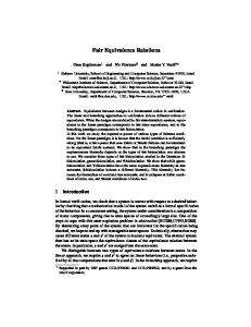
For the computer experiments the following values were assigned: l 苷 0.6328关mm兴 , z2 苷 4关m兴 , and scaling parameter a 苷 6关1/mm兴 . Such values lead to z2 兾2 .. zRayleigh , and thus the conventional Gaussian suffers from significant spread. Figure 2 shows a few lateral cross sections along the x axis of the amplitude prof ile of the desired beam at y 苷 0 for z 苷 1, 2, 3, 4 m. Figure 3 shows
(6) Multiplying Eq. (6) by i and adding it to Eq. (5) yields R ˜ ⴱ 共u, v; z兲dz u˜ 共u, v, z兲h ˜f 共u, v兲 苷 Dz Rd . (7) ˜ 2 dz j h共u, v; z兲j Dz If one writes explicitly the Fresnel transfer function that is given by Eq. (8) as ∂ µ 2p ˜ z exp关2iplz共u2 1 v2 兲兴 , (8) h共u, v; z兲 苷 exp i l the final result is ∂ µ 1 Z 2p z f˜ 共u, v兲 苷 u˜ d 共u, v, z兲exp 2i Dz Dz l 3 exp关iplz共u2 1 v2 兲兴dz ,
(9)
where Dz is the length of Dz . The OE to be fabricated is simply the inverse Fourier transform of f˜ 共u, v兲, which is given in Eq. (10). Note that, according to Eq. (10), Dz may consist of several separate 3-D regions. To examine the performance of the proposed method we carried out computer experiments. We chose the desired 3-D beam to be a Gaussian beam, which diverges more slowly by a factor of 2 than a conventional Gaussian beam with the same waist. Furthermore, the region of interest was determined to be from z 苷 0 to z 苷 z2 , and the waist of the Gaussian beam was chosen to appear in z 苷 z2 兾2; i.e., the Fourier transform of the desired beam is of the form
Fig. 2. Cross sections of the amplitude profile of the desired beam for z 苷 1, 2, 3, 4 m (top left, top right, bottom left, bottom right, respectively).
∏ ∑ ∏ ∑ p z2 u˜ d 共u, v, z兲 苷 exp 2 2 共u2 1 v2 兲 exp ipl共u2 1 v2 兲 a 4 µ ∂ ∑ ∏ 2p z . 3 exp i z exp 2ipl共u2 1 v2 兲 (10) l 2 We assume a unit intensity plane wave that illuminates the OE. Substituting u˜ d 共u, v, z兲 of Eq. (11) into
Fig. 3. Same as Fig. 2 but for a conventional Gaussian beam.
March 15, 2000 / Vol. 25, No. 6 / OPTICS LETTERS
365
Finally, Fig. 5 presents prof iles of all three beams as a function of the propagation distance. One can see that the obtained beam does not diverge as fast as the Gaussian beam, at the expense of lower contrast (higher sidelobes) at the waist. In the final set of simulations the desired complex amplitude is a nondiffractive, rectangular (top-hat) beam whose width and length were chosen to be D 苷 1.22关mm兴 , which is small enough to yield signif icant diffraction to compensate for. The region of interest lies from z 苷 0关m兴 to z 苷 z2 苷 2.5关m兴 , and the wavelength is l 苷 0.6328关mm兴 . Thus the Fourier transform of the desired complex amplitude within the region of interest is ∂ µ 2p z sinc共Du兲sinc共Dv兲 . u˜ d 共u, v, z兲 苷 D2 exp i l Fig. 4. Same as Fig. 2 but for the beam obtained with the suggested filter.
(12)
Hence, following Eq. (10), the Fourier transform of the optimal DOE for this case is ∏ ∑ 2 ˜f 共u, v兲 苷 2D sinc共Du兲sinc共Dv兲 exp ipl z2 共u2 1 v2 兲 plz2 共u2 1 v2 兲 2 ∑
∏ z2 2 2 3 sin pl 共u 1 v 兲 . 2
Fig. 5. Cross sections of the amplitude profile as a function of the distance: (a) the desired beam, ( b) a conventional Gaussian beam, (c) the result obtained with the suggested filter.
(13)
Finally, Fig. 6(a) shows the cross section of a beam whose complex amplitude in the middle range, i.e., for z 苷 z2 兾2 苷 1.25关m兴 , has the desired shape. One can see that this beam diverges fast. Figure 6(b) provides a cross section of the resultant beam when the suggested DOE is used. Here, one can see the close match to the desired beam. We have proposed a novel method for the synthesis of 3-D complex amplitude distributions. An explicit analytical equation for obtaining the OE required for the task was derived. This OE provides the optimal complex amplitude distribution that satisfies the Fresnel, free-space propagation, transformation with respect to a desired arbitrary 3-D complex amplitude function in some 3-D region of interest. The criterion of optimality was chosen to be the MMSE, which is commonly used in many applications. Computer simulations demonstrate a single example of the proposed method’s capability and its possible uses. D. Mendlovic’s e-mail address is
[email protected]. References
Fig. 6. Cross sections of the amplitude profile as a function of distance: (a) a beam with a rectangular aperture in middle range, ( b) the result obtained with the suggested filter.
the same cross sections for a conventional Gaussian beam with the same waist width as the desired beam. Figure 4 presents the same cross sections as obtained by the filter of Eq. (12) and the optical setup of Fig. 1.
1. J. R. Leger, in Micro-Optics: Elements, Systems and Applications, H. P. Herzig, ed. (Taylor & Francis, London, 1997), Chap. 9, pp. 223–257. 2. Z. Zalevsky, D. Mendlovic, and R. Dorsch, Opt. Lett. 21, 842 (1996). 3. D. Mendlovic, Z. Zalevsky, G. Shabtay, and E. Marom, Appl. Opt. 35, 6875 (1996). 4. R. W. Gerchberg and W. O. Saxton, Optik 35, 237 (1972). 5. J. Durnin, J. Opt. Soc. Am. A 4, 651 (1987). 6. Z. Jiang, J. Opt. Soc. Am. A 14, 1478 (1997). 7. J. Rosen, Opt. Lett. 19, 369 (1995).