International Journal on Electrical Engineering and Informatics ‐ Volume 5, Number 3, September 2013
Optimal Tuning of PID Controllers for Hydrothermal Load Frequency Control Using Ant Colony Optimization M. Omar1, M. Soliman1, A. M. Abdel Ghany2, and F. Bendary1 1
Faculty of Engineering at Shoubra, Benha University 2 Faculty of Engineering, Helwan University
[email protected]
Abstract: This paper proposes a novel Artificial Intelligence technique known as Ant Colony Optimization (ACO) for optimal tuning of PID controllers for load frequency control. The design algorithm is applied to a hydrothermal power system consisting of two control areas one hydro and the other is thermal with reheat stage. To make the system in realistic form, the system nonlinearities represented by Generation Rate Constraint (GRC), Dead Band, wide range of parameters are introduced. Three different cost functions have been suggested for tuning the PID controllers. The system has been tested for various load changes to reveal the effectiveness and robustness of the proposed technique. Keywords: Load Frequency Control (LFC), PID, Cost Function. 1. Introduction In the large scale electric power systems with interconnected areas, Load Frequency Control (LFC) plays an important role. The LFC is aimed to maintain the system frequency of each area and the inter-area tie line power within tolerable limits to deal with the fluctuation of load demands and system disturbances. These important functions are delegated to LFC due to the fact that a well-designed power system should keep voltage and frequency in scheduled range while providing an acceptable level of power quality. A wide variety of different advanced control methods have already been proposed in the literature for LFC [1]. Usually LFC is organized in three levels: Primary control is done by governors of the generators, which provide immediate action to sudden change of load. Secondary control keeps frequency at its nominal value by adjusting the output of selected generators (controller is needed). Tertiary control is an economic dispatch that is used to operate the system as economically as possible [2]. During the last years several researches and techniques had been applied to the field of LFC. A robust LFC via H∞ and H2 control theories has been designed in [3] with different cases for the norm between load disturbance and frequency deviation output. The main disadvantage of these two methods is that these introduce a controller with the same plant order, which in turn doubles the order of the open loop system, and makes the process very complex specially for large scale interconnected power systems. In [4] another technique had been suggested for tuning the parameters of a PID controller for LFC in a single area power system by using particle swarm optimization (PSO). Genetic Algorithm (GA) [5] also used inthis field for the purpose of selection of PID parameters. In [6] LFC with fuzzy logic controller (FLC) considering nonlinearities and boiler dynamics is introduced which has greatly improved the performance of the controller. In [1] new approach using Imperialist Competitive Algorithm (ICA) for multi area LFC has been introduced. Another method for tuning PID controller using Bacteria Foraging Optimization (BFO) for two area system with different step load changes has been applied in [7]. This paper introduces a new Artificial Intelligence (AI) technique (ACO) for optimal tuning of PID controllers. The motivation behind this research is to prove and demonstrate the Received: June 10th, 2013. Accepted: August 23rd, 2013
348
M. Omar, et al.
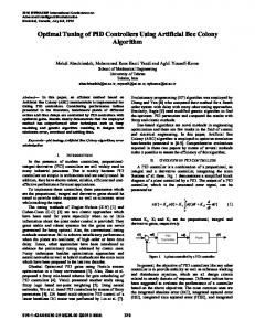
robustness of ACO based PID, and to improve the transient response of both frequency deviation and tie line power under various loading conditions in presence of system nonlinearities. The paper is organized as follows: Section I, introduction. Section II, focuses on the modeling of two area power system. A brief description for ACO technique is illustrated in Section III. In Section IV, simulation and results obtained from the application of ACO tuned PID to the system. Sections V, conclusion. 2. Two area power system A. System Model A two area model of a hydrothermal power station including nonlinearities is shown in figure (1). Complete description for symbols used in the block diagram is given in table (I).
Figure 1. Block diagram of two area model. Table 2. Symbols identification Symbol
Quantity
Value
T1,T2,T3
Governor Time constants of hydro area
0.6, 5, 32 s respectively 1s 20 HZ/Pu MW, 3.76 s respectively 3 Hz/Pu MW 0.383 Pu MW/ Hz 0.08 s 10 s
Tw
Hydro turbine time constant
K1,Tp1
Hydro plant gain and time constant
R1 B1 Tg Tr
Regulation of hydro area Biasing factor of hydro area Governor Time constant of thermal area Reheat time constant
Kr
P.u megawatt rating of high pressure stage
0.5
Tt
thermal turbine time constant
0.3 s
K2, Tp2
thermal plant gain and time constant
120 HZ/PuMW, 20 s respectively
R2 B2 P12
Regulation of hydro area Biasing factor of hydro area Synchronization coefficient
2.4 Hz/PuMW 0.425 PuMW/ Hz 0.545PuMW
349
Optimal Tuning of PID Controllers for Hydrothermal Load Frequency
The steam chest time constant which is related to the non-reheat stage ranges from 0.1 to 0.5 s whereas the time constant for the reheat stage (which is series cascaded with the nonreheat stage) ranges from 4 to10 s. Nonlinearities incorporated in this model represent in GRC and governor dead band (backlash). The first one as its name implies (GRC) respects for the turbine illustrates the limitation on the generation rate of change in the output generated power due to the limitation of thermal and mechanical movements [8], for thermal stations it is taken to be 0.1 Pu Mw per minute [9]. The second nonlinearity is defined as the total magnitude of a sustained speed change; within which there is no resulting change in valve position. All types of governors have a dead band in response, which is important for power system frequency control in the presence of disturbances, here it is taken to be .0005 [9]. B. Control Technique The controller type used here is a PID controller with the transfer function given in (1):
k(s) = kp + ki / s + kds
(1)
Where kp, ki, kd are proportional, integral and differential gains respectively. The input to the controller is the area control error (ACE), and the output is u(s) as shown in (2).
u(s) = −k(s) * ACE
(2)
The function of each part of a PID controller can be described as follows, the proportional part reduces the error responses of the system to disturbances, the integral part eliminates the steady-state error, and finally the derivative part dampens the dynamic response and improves the system stability [10]. C. Cost Function Three different cost functions had been suggested for ACO technique for tuning the parameters of the PID controller. First cost function: This cost function as shown in (3) minimizes the integrated square error e(t).
∞ 2 f1 = ∫ (e(t )) dt 0
(3)
Second cost function: In this method [11], the actual closed-loop specification of the system with controller, rise time (tr), maximum overshoot (Mp), settling time (ts), and steady state error (ess) are used to evaluate the cost function. This is done by summing the errors between actual and specified specification as given by (4).
f2 =
1 [c1(tr −trd) + c2(Mp − Mpd) + c3(ts −tsd) +c4(ess −essd)]
(4)
Where, c1: c4 are positive constants (weighting factors), their values are chosen according to prioritizing their importance, (trd) is the desired rise time, (Mpd) is the desired maximum overshoot, (tsd) is the desired settling time, and (essd) is the desired steady state error.
350
M. Omar, et al.
Third cosst function: A perform mance criterion n in the time doomain is proposed as given inn (5). 1 f3 = −β −β (1− e )(M p + ess) + e (ts − tr )
(5)
c function can c satisfy the designer requuirements usingg the weightinng factor valuee This cost ( β ). Thee factor is set larger than 0.77 to reduce thee overshoot annd steady-statee error. On thee other hand is set smallerr than 0.7 to reeduce the rise tiime and settlinng time [11]. All A of these costt nimized subjeccted to: functions have been min
minn max x kp ≤ kp ≤ kp
ki
minn max ≤ ki ≤ ki
kd
minn
≤ kd ≤ kd
max
3. Ant Coolony Optimizzation: Overviiew The ant a colony opttimization algorithm (ACO)) is a probabiilistic techniquue for solvingg computatiional problems which can be b reduced forr finding goodd paths throughh graphs. Thiss algorithm m is a member of o the ant colonny algorithms family, in swarrm intelligencee methods, andd it constituutes some metaaheuristic optim mizations.
Figure 2. Ants from nest to the source of food. f Initiallly proposed by y Marco Doriggo in 1992 in his h PhD thesis [8]. The first algorithm wass aiming too search for an n optimal path in a graph, baased on the behhavior of ants seeking a pathh between their colony and a a source of food. In the t natural woorld, ants (iniitially) wanderr randomlyy, and upon finding food return to their coloony while layinng down pheroomone trails. Iff other antss find such a path, they aree likely not to keep travellinng at random, but to insteadd follow thee trail, returnin ng and reinforccing it if they eventually finnd food. Over time, t however,, the pheroomone trail starrts to evaporatte, thus reducinng its attractivve strength. Thhe more time itt
351
Optimal Tuning of PID Controllers for Hydrothermal Load Frequency
takes for an ant to travel down the path and back again, the more time the pheromones have to evaporate. A short path, by comparison, gets marched over more frequently, and thus the pheromone density becomes higher on shorter paths than longer ones [9]. Figure (1) [10] illustrates the behavior of real ants in searching the source of food. A flowchart for this optimization process is shown in figure 2.
Figure 3. Flowchart of ACO based PID control system. The algorithm of ACO is shown in (6) and (7), where: P is the probability, α, β, τ are parameters related to ACO algorithm, d is the distance, Q being a constant parameter, Lk is the kth ant solution, ρ is a parameter used to avoid unlimited accumulation of the pheromone trails and m is the number of ants. The first equation describes the probability of the ant to move between the two nodes i and j, while the second one describes the local updating of pheromone after travelling from a node to another one. β ⎛1⎞ τij (t)α ⎜⎜ ⎟⎟ ⎝ dij⎠ pij (t) = β (6) α ⎛⎜ 1 ⎞⎟ τ ( ) t ∑ ij ⎜ dij⎟ j∈nodes ⎝ ⎠
τ ij (t + 1) = (1 − ρ )τ ij (t ) +
Q ∑ L k∈colonythat m
(7)
usededge (i , j )
Advantages of ACO technique represent in: • Positive Feedback accounts for rapid discovery of good solutions • Distributed computation avoids premature convergence. • The greedy heuristic helps finding acceptable solution in the early solution in the early stages of the search process.
352
M. Omar, et al.
Disadvantages of ACO on the other hand represent in: • Lower convergence than other Heuristics. • Performs poorly for problems have larger than 75 nodes. • No centralized processor to guide the ACO towards good solutions [11]. In this paper ACO algorithm is used for optimal tuning of PID parameters for both the two areas at the same time by minimizing the required cost function. 4. Simulation and results In this section the different values of PID parameters tuned using ACO technique for the early mentioned three cost functions are shown in table (II), where area 1 is the hydro power station, and the steam power station is the second one. Table 2. Values of PID gains Hydro plant
Steam plant
Kp
Ki
Kd
Kp
Ki
Kd
st
.84
.86
.66
.9
.98
.98
nd
.02
.4
.42
.4
.15
.88
rd
.81
.42
.33
.56
.21
.27
1 cost function 2 cost function 3 cost function
Different cases of load disturbances are applied to the model to demonstrate effectiveness and robustness of the proposed technique. Case 1: steploadchange of 2%in both areashas been applied to the system. The responses of frequency deviation in area 1, tie line power, and control signals for the two areas in this case are shown in figure (4, 5, 6, and 7). From these responses it is clear that ACO tuned PID for the three cost functions succeeded in damping all oscillations, minimizing settling time and reducing overshoot. It is clear that the control signals in the two areas are in acceptable values. Also it is clear that the 3rd cost function based PID has the best performance.
0.06
1st cost function 2nd cost function 3rd cost function
freq u en cy d ev iatio n in area 1
0.04 0.02 0 -0.02 -0.04 -0.06 -0.08 -0.1 -0.12 -0.14
0
10
20
30
40
50
60
70
time
Figure 4. Frequency deviation response in area 1 for case 1.
353
80
Optimal Tuning of PID Controllers for Hydrothermal Load Frequency
0.01
1st cost functiondata1 2nd cost function 3rd cost function
0.005
p tie
0
-0.005
-0.01
-0.015
-0.02
0
10
20
30
40
50
60
70
80
time
Figure 5. Tie line power deviation response for case 1.
0.12
1st cost function 2nd cost function 3rd cost function
0.1
u1
0.08
0.06
0.04
0.02
0
0
10
20
30
40
50
60
70
80
time
Figure 6. Control signal in area 1 for case 1.
0.08
1st cost function 2nd cost function 3rd cost function
0.07
0.06
u2
0.05
0.04
0.03
0.02
0.01
0
0
10
20
30
40
50
60
time
Figure 7. Control signal in area 2 for case 1.
354
70
80
M. Omar, et al.
Case 2: another violent test by changing the load disturbance nature from step to ramp shape is discussed in this case. This case is considered a simulation for realistic load change case where the load disturbances as shown in figure (8,9) simulate what happens in fact. For realistic power system load disturbance takes place in ramp shape within certain time not in no time as in step case. The responses of frequency deviation in area 1, tie line power, and control signals for the two areas in this case are shown in figure (10, 11, 12, and 13). The results proved the robustness of the propoed algorithm.
lo a d d is tu rb a n c e in a re a 1
0.015
0.01
0.005
0
0
5
10
15
20
25
30
35
40
45
50
45
50
time
Figure 8. Load disturbance in area 1 for case 2.
0.035
0.03
lo a d d istu rb a n c e in a re a 2
0.025
0.02
0.015
0.01
0.005
0
0
5
10
15
20
25
30
35
40
time
Figure 9. Load disturbance in area 2 for case 2.
355
Optimal Tuning of PID Controllers for Hydrothermal Load Frequency
0.03
1st cost function 2nd cost function 3rd cost function
freq u n cy d ev iatio n in area 1
0.02 0.01 0 -0.01 -0.02 -0.03 -0.04 -0.05 -0.06
0
10
20
30
40
50
60
70
80
time
Figure 10. Frequency deviation response in area 1 for case 2.
0.015
1st cost function 2nd cost function 3rd cost function
0.01
p tie
0.005
0
-0.005
-0.01
-0.015
0
10
20
30
40
50
60
70
80
time
Figure 11. Tie line power deviation response for case no 2.
0.05
1st cost function 2nd cost function 3rd cost function
0.04
0.03
u1
0.02
0.01
0
-0.01
-0.02
-0.03
0
10
20
30
40
50
60
time
Figure 12. Control signal in area 1 for case 2.
356
70
80
M. Omar, et al.
0.04
1st cost function 2nd cost function 3rd cost function
0.035
0.03
u2
0.025
0.02
0.015
0.01
0.005
0
0
10
20
30
40
50
60
70
80
time
Figure 13. Control signal in area 2 for case 1. Case 3: the load disturbances are -2% in both areas with 50% increasing in K2, Tp2, R2, K1, Tp1, and R1. The responses of frequency deviation in area 1, tie line power, and control signals for the two areas in this case are shown in figure (14, 15, 16, and 17). It is clear that ACO based PID still robust to variation in system parameters. 0.15
1st cost function 2nd cost function 3rd cost function
frequency deviation in area 1
0.1
0.05
0
-0.05
-0.1
0
10
20
30
40
50
60
70
80
time
Figure 14. Frequency deviation response in area 1 for case 3. 0.02
1st cost function 2nd cost function 3rd cost function 0.015
ptie
0.01
0.005
0
-0.005
-0.01
0
10
20
30
40
50
60
70
time
Figure 15. Tie line power deviation response for case 3.
357
80
Optimal Tuning of PID Controllers for Hydrothermal Load Frequency
0
-0.02
1st cost function 2nd cost function 3rd cost function
-0.04
u1
-0.06
-0.08
-0.1
-0.12
-0.14
0
10
20
30
40
50
60
70
80
time
Figure 16. Control signal in area 1 for case 3. 0
1st cost function 2nd cost function 3rd cost function
-0.01
-0.02
u2
-0.03
-0.04
-0.05
-0.06
-0.07
-0.08
0
10
20
30
40
50
60
70
80
time
Figure 17. Control signal in area 2 for case 3. The settling time (ts) and percentage overshoot (%o.s) for ∆f1 and ptie for the above cases are given in table (III). Table 3. Case 1 ∆f1 1st cost function 2nd cost function 3rd cost function
Case 2 ptie
∆f1
Case 3 ptie
∆f1
ptie
ts
%o.s
ts
%o.s
ts
%o.s
ts
%o.s
ts
%o.s
ts
%o.s
20
12.6
40
1.6
46
5.35
60
1.15
30
13.2
40
1.75
50
11.9
60
1.6
60
5.14
70
.07
47
12.5
60
1.58
32
12.7
64
1.67
64
5.87
70
.09
42
13.3
63
1.7
358
M. Omar, et al.
Conclusion In this paper a PID controller which is tuned via ACO has been strongly proposed for the multi area LFC problem. The results declared that ACO based PID is capable to guarantee robust stability and robust performance under various load conditions and changes in system parameters for three different cost functions. The proposed controllers succeeded in damping all oscillations, minimizing settling time and reducing overshoot, this reduces wear in control valves and gates. In the future work we intend to apply the ACO algorithm to the renewable energy power stations as wind turbine for example; also we intend to specify the upper limit of load disturbances which may cause the instability problem of the power system. References [1] M. Soroush, M. Ali, S. Mohammad, and A. mohammad, “Tuning of PID Controller for Multi Area Load Frequency Control by Using Imperialist Competitive Algorithm,” ISSN 2090-4304Journal of Basic and Applied Scientific Research, 2012. [2] TAN Wen, “Load Frequency Control: Problems and Solutions,” Proceedings of the 30th Chinese Control Conference, Yantai, China, July 22-24, 2011. [3] A. Bensenouci, A. M. Abdel Ghany, “Performance Analysis and Comparative Study of LMI-Based Iterative PID Load-Frequency Controllers of a Single-Area Power System,” WSEAS Transactions on power systems Issue 2, Volume 5, April 2010. [4] M. Ahmed, “AI-Based Decentralized Load Frequency Controllers for Interconnected Power Systems,” Cairo, master of science, 2009. [5] M. E-D. Mandour, E. S. Ali, and M. E. Lotfy, “Robust Load Frequency Controller Design Via Genetic Algorithm and H∞,” Modern Electric Power Systems, Wroclaw, Poland MEPS’10 – paper P16, 2010. [6] A. Kumar, A. Ahmad, A. Grover, and U. Gupta, “Load Frequency Control Using Fuzzy Logic,” International Journal of Scientific and Research Publications, Volume 2, Issue 7, 1ISSN 2250-3153, July 2012. [7] E. Salim Ali , S. M. and Abd-Elazim, “Optimal PID Tuning for Load Frequency Control Using Bacteria Foraging Optimization Algorithm,” Proceedings of the 14th International Middle East Power Systems Conference (MEPCON’10), Cairo University, Egypt, December 19-21, Paper ID 191, 2010. [8] H. Bevrani, “Robust Power System Frequency Control”, Springer Science+Business Media, LLC, 2009. [9] J. .Nanda, A.Mangla, and S.Suri, “Some New Findings on Automatic Generation Control of an Interconnected Hydrothermal System with Conventional Controllers,” IEEE Transactions on energy conversion, vol.21, No.1:pp 187-194,Margh 2006. [10] G. Tan, Q. Zeng, S. He, and G. Cai, “Adaptive and Robust Design for PID Controller Based on Ant System Algorithm,” School of Information Science and Engineering, Central South University Changsha 410083, Hunan Province, P. R. China. [11] A. Mohamed, “Optimization Techniques for Tuning the Controller of a Permanent Magnet Brushless Motor,” Cairo, master of science, 2012. [12] Colorni, M. Dorigo et V. Maniezzo, “Distributed Optimization by Ant Colonies, ” actes de la première conference européennesur la vie artificielle, Paris, France, Elsevier Publishing, 134-142, book style 1991. [13] M. Dorigo, “Optimization, Learning and Natural Algorithms,” PhD thesis, Politecnico di Milano, Italie, 1992. [14] M. Dorigo et L.M. Gambardella, “Ant Colony System : A Cooperative Learning Approach to the Traveling Salesman Problem, ” IEEE Transactions on Evolutionary Computation, volume 1, numéro 1, pages 53-66, 1997. [15] M. Dorigo, and Th. Stu , “Ant Colony Optimization,” tzle.p. cm.''A. Bradford book''. Includes bibliographical references (p.).ISBN 0-262-04219-3 (alk. paper).
359
Optimal Tuning of PID Controllers for Hydrothermal Load Frequency
M. Omar O was born rn in Cairo, Eggypt, on Marcch 1, 1988. He received thee B.Sc. degree in ellectrical enginneering with honor h degree in 2010 from m Faculty of Engineeering at Shoubbra, Benha University, Cairro, Egypt. Onn r his work w in this faaculty as an innstructor in thee Januaaryt 2011, he received Electrrical Engineeriing Departmennt. Currently hee is M.Sc reseaarcher in powerr system m engineeringg. His researrch activity includes studyying the loadd frequeency control (L LFC) and poweer system analyysis.
A .M M. Abdel Ghan ny was born inn Cairo. He reeceived his B.Sc. and M.Sc. degrees in 1980 andd 1987 from thhe Electrical Power P System and Machiness C Egypt. Frrom 1989 to 19994, he got hiss deparrtment, Helwann University, Cairo, Ph.D. in Computerr Controlled Systems S from the t Institute of o Control andd ms Engineerinng, Technical University U of Wroclaw W Polannd. From 19944 System to 199 99, he workedd as an assistannt professor at the departmennt of Electricall Mach hines and Pow wer System, Heelwan Universsity, Cairo Egyypt. From 12-Januaary 2011 until now he is Department D Heead of Electriccal Power andd Machiness Engineering in the Dept. of o Electrical Machines M and Power P Engineeering, Helwann Universityy, Helwan, Egypt. His research activity includes Conntrol of Poweer System andd Electricall Machine, Auttomatic Controol Systems. F. Ben ndary A was born b in Cairo. He received hiis B.Sc. and M.Sc. M degrees inn 1966 and 1979 froom Ain shams University, and a Cairo Uniiversity, Egyptt respecctively. He obttained Ph.D. from paris sud inn 1983. He is a full professorr in facculty of engineering shoubra,, Benha univerrsity since 1995 till now. Hiss researrch activity inccludes Control, Power System m analysis and optimization.
360