ble to use a computer to optimize the system once the system layout is ..... Advancements in both software and hardware in recent years are so great that.
Optimization for Component Selection Hydraulic Systems Petter Krus
.
In
Arne Jansson
Jan-Ove Palmberg Division of Fluid Power Technology Department of Mechanical Engineering Linköping University, 8-58183 Linköping, 8weden
ABSTRACT The design process is an interactive feedback process where the performance of the design is compared with the performance specification . Usually this is a manual process where the designer makes a prototyp e system which is tested and modified until satisfactory. Using an optimization strategy and a simulation model of the system it is possible to use a computer to optimize the system once the system layout is established. In the general case, however , the total number of parameters of all components in a system is to large to be handled effectively by numerical optimization. The approach used here is to introduce a set of performance parameters that uniquly define the components if they are assumed to be optimized in some sense. The performance parameters for a component are few compared to the total number of parameters in a component. This reduces the optimization problem to more realistic proportions and optimization of even rat her complex system may be performed.
l
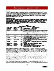
INTRODUCTION The design process can generally be described by Fig.l. At the highest level the system configuration is established and at the lowest level parameter values of the system are determined. There is also an intermediate level of component selection where complete sets of parameters are chosen. This means that we can distinguish three levels in the design process.
:=-
System configuration
Performance specijication
, .'-.
Component selection
...... Simulation
, Optimization of parameters
Figure 1: The design process as an iterative feedback process Optimization using computer simulation can be used for optimizing parameters in the design. Using an expert system it can even be possible to let the computer design the system from a performance specification. The component selection can also be done by the computer using some optimization strategy. Here the two lower levels will be discussed. Optimization of controI systems and control strategies for hydraulic systems using dynamic simulation has been described by several authors , ie K-E Rydberg [8] who used it for optimization of hydrostatic drives and J Roth [7] who used for optimizing control parameters for position control of hydraulic servo systems using the DSH package developed at RWTH in Aachen [2]. In these papers optimization was succesfully used to determine some parameters . Here, we have tried to make an overall optimization of the system which include most parameters of the system. In order to avoid the optimization becoming too large and complex some assumptions are made. Since the optirnization is based on component selection rather than component design, the assumption is that the individual components in some sense already are optimized. A consequence of this is that most parameters of a component (or subsystem) can be described as simple monotonus functions of a very limited set of performance parameters, e.g. the size. This has been shown for valves by Nakada [5] who 2
presented a relationship between size and response for proportional and servo val ves, and the same philosophy is evident in the popular efficiency models for pumps and motors proposed by Wilson [9]. This concept can be extended further by making a true optimization of each component parameter set given the performance parameters. The performance parameters will than act as constraints for the local optimization. If the component/subsystem is sufficiently simple this optimization can even be performed analytically. In this way it is possible to handle the complexity and to optimize all parameters in the system.
Global optimization
perjormance parameters
global parameters
Component Local
Figure 2: Global and local optimization of a system THE COMPLEX ALGORITHM The optimization of a hydraulic circuit can be described as a multivariable constrained optimization problem. The problem is to maximize the function
subjected to the constraints
The implicit variables X N +ll ... ,XM are dependent functions of Xl, .... X N . The constraints Ck and Hk are either constants or functions of Xl, .... XN. One method that is very suitable for this kind of problem is the Complex method of M J Box
3
[1]. In the implementation used here an initial complex of k points is generated. The variable at each point is generated using random number. (1)
Here rij is arandom number in the interval [0,1]. If the implicit constraints are not fulfilled a new point is generated until the implicit constraints are fulfilled. The number of points k in the complex must be k ~ N + 1 where N is the number of independent variables. The object function is evaluated at each point. The point having the lowest value is replaced by a point reflected in the centroid of the remaing points by a factor a. Xij(new) = a(xic - xij(old)) +
Xic
(2)
The centroid is calculated as 1
k
Xjc = -k-[IJXjj - xjj(old)] - 1 j=1
(3)
Box [1] recommends O:' = 1.3. If a point repeats as the lowest value on consecutive trials it is moved one haH the distance to the centroid of the remaining points. However, in order to handle the situation where there is a local minima located at the centroid, it is gradually moved towards the maximum value if it still repeats as the lowest value. Xjj(new)
= [xij(old) + f.Xjc + (1 -
f.)xi,max]/2
(4)
where
(5)
here kr is the number of times the point has repeated and nr is a constant. Here nr = 4 has been used. If a point violates the implicit constraints it is moved haHway towards the centroid. In order to handle the case of the centroid violating the implicit constraint the point is gradually moved towards the maximum value if it still violates the implicit constraint using eq (4) but with
(6)
where k c is the number of times the point has violated the constraint.
4
SIMULATION, REAL TIME AND BEYOND Since optimization requires that the system is simulated a rather substantial number of times it is important that the simulation is numerically highly effective. Simulation is therefore carried out using information propagation modelling IPM. This method is described in Krus, Jansson , Palmberg and Weddfelt [4] and in Krus , Jansson and Palmberg [3]. This is a technique that is numerically very robust and highly effective. It has made it possible to simulate even rat her complex systems in real time. If a simulated system becomes to complex it can be split and the different components can be simulated on separate processors, since this is very easy to administrate using IPM. The concept of variable time step is of course not relevant to real time simulation since all part of a simulation must be simulated at the same pace. In an off-line situation, however , as in system optimization , variable time step could be used to push the simulation speed way beyond real time. In the examples shown here, however, fixed time step has been used and each simulation took about 5.6 sec on an Apple Macintosh IIfx computer. However , if the system violated some implicit constraint during the simulation the simulation was aborted and the algorithm could proceed directly with the next point. This saved a considerable amount of time during the search for allowed starting points for the initial complex .
OPTIMIZATION OF A HYDRAULIC SYSTEM In this example the component sizes only have been used as performance parameters . The size s is a dimensionIess scaling factor that acts upon the datafile of an existing component. Each parameter in the data file is scaled using s.
(7) here K, is an exponent that depends on the parameter. The K, value for each parameter can be determined using the assumption that a component is optimized for each size. As an example, the system in Fig 3 was optimized with respect to size of the different components and pressure level. It consists of a motor driving an inertia load plus a constant load. The motor is controlled by a valve using position feedback of the load position. Two variable displacement constant pressure pumps are also included. The only parameters given a priori are those concerned with the load, the capacitances surrounding the valve and the pump speed. The task of the system was to move the load 30 radians in one second using position feedback. All the three volumes where lO-3 m 3 with a bulk modulus of 109 Pa. The load inertia was O.lkgm 2 and the externaI torque was 30Nm . The optimization variables are; the sizes of the motor, Smotor, val ve , Stia/tie, and pumps, spumph Spump2 which are performance parameters, and the gain of the position feedback kp and the reference pressure for the pump PreJ, which are global
5
y
y ref
[low/speed (pressure/jorce)
----.
..
............
characlerislics
Figure 3: parameters. This gives a total of six variables. The cost of each component was assumed to be proportional to the size except for the pumps which was assumed to be proportional to (Spump )",p. The cost of the system can then be expressed as {tli!e
Csyst
=
1(lsmotor
+ 1(2 svalve + 1(3[(Spumpl)"'P + (Spump2Y"P] + 1(4 Jo
P3Q3 dt
(8)
where the 1(4 term represents the lifetime energy cost of the system. A penalty function on the position error was also introduced
(9) Finally it was found that if the initial points of the system had very high gain, there would be a situation where the gain did not affect the object funtion. This is because the saturation in the valve would cause the system to behave like a relay type regulator which is very insensitive to the gain. To prevent this a penalty was also placed on saturation of the valve.
(10) where
z
={
l1(p(Yref
-oy) -
xvmaxl
if
1(plYref -
Yl> X vmax
otherwise
(11)
The total object function is thus ( 12) The only implicit constraints was that the position must not go below -10% of the input step at any point of the simulation. If it did, the simulation was aborted immediatly and the algorithm proceeded directly to the next point. 6
Since some of the sizes can vary over several orders of magnitudes it can be preferable to let the complex algoritm work with the logarithms of the parameters instead of the parameters themself. The following new variables were therfore introduced for the optimization. Smotor
-
log Smotor
Svalve
-
log Svalve log k p
f{p Spumpl
log Spumpl
Spump2
log Spump2
Prej
=
logPrej
The allowed interval for the parameters were Smotor
E
Spumpl
E
Spump2
E
Sval ve
E
f{p
E
Prej
E
[-2, l] [-2, l] [-2, l] [-l, l] [-5,-2] [5 , 8]
The initial complex was generated by random numbers until eight points was found that satisfied the implicit constraint. The optimization process can be studied in Figs 4-7 where the variation in the optimization variables are shown. S valve 2 .00 1.50
~---,.,.-,-.-----......,.------,...----...,.
::
::: ; :: ij ;.... .. .. ..............:..• .. • .•...•. . . . .. ..... . . .! ' ! .. ! .. 1! ~~ jl UH~LL ~ ~ ~ .: ~~
~
~
o •••••• • • •
1.00 ~~H. J~1. Hii~t~t i 1~~. i ... ..... . ... ...:......... .. ... ... . ; ... ...... ...... . . .50
l~h~ iii· r~il ~~~1~i:l~.!!/~.~.~.\~~~tg.''--f;'.A. ..;''';~+. gain ..;::. ..'::. ...... ............... ........ : ................ . ~1 i ~i ~ i:' r ir " : 1 : : :.:.:.~.:.::-:-::
:;.:~ .1.
i.: :.:.
.00
.~
.
"~
.'.1. . . . . . . . . . . . .. . .. .... ..........: .. ..... ..... ... . . lU'I,~~_ _......-
valve
-2 .50 -3.00 -3 .50 -4.00 -4.50
- .50 -1 .00
-2.00
+--~J.L.-II.I.4-----+------I-------+
.0
100.0
200.0
300.0
- 5.00
400.0
n
Figure 4: Logarithms of valve size and gain
7
1.00
s pump -r--T"'""Trr---r-----r------r-------,
.50 .00 pump 1
- .50 -1.00 -1.50
- 2 .00
.........- - - - _ I
+--=--L-..l.IJ....!....-'IL..~------4----
400.0
300 .0
200.0
100.0
.0
n
Figure 5: Logarithms of pump sizes
S motor 1.00
....---r-~-r------,.----"""'T"----""T
.j~
.50
. •• .
~ .,.
• • •• • • •••••••••• :•• •••••••••••••••• ~ • ••• • •• • •• •• •••••
:
.00
.
:
! . ~:
~
ii r- :
F: ~ .
: .: , .....-...... •.+"•.:.• : : ~
~.. . ..
···
;
-1.50
.. .
7.50
motor
,;! : :r'!!.'.~I·c-·Y"'i''''~'i"..:~ ~.: :· · ·· · ·· · ···~· · '· ·· · ·· · ·· ··'··
pref
7.00
6.50
:.. ].: ...1:::::.::::::::::::1:.::.:: .. :::: .. ::.1.::.:.:.: .. :::::: .. ·· ..
-1.00
- 2.00
:
""'.1~Mh.AM~~t"f'~.......""""--.:.. : ~;'. : ... ..: : :, _j
-.50
:
8 .00
6.00
.. .
.... .. ... ~ ........... ... ... .:.. ... ... ......... . ~ ... .... ... ..... ..
5 .50
~---=-...!-----4-----+-----~----+
.0
100.0
200 .0
300 .0
5.00 400 .0
n
Figure 6: Logarithms of motor size and system pressure
8
F
-10.0
-r------r------r------r-------,
... .... .... . . . . .."r
-15.0
-20.0
. .........:....... .. .... ... .
.. ........... .
.
-25.0
- 30 .0
. ITTrJ.. ; ...... · ........ ..
. .... ..... .:.. .. ...... .. .... .
-
1---'l--'I~~~J..II..I.-.I..L~L..-.--+-----I
.0
200.0 n
100 .0
300 .0
400.0
Figure 7: Object function
e [rad]
eref [rad]
40 .0
~--~--~--~--~---r-----.
40 .0
30.0
...............................................'1"'9------+
30 .0
20 .0
l
20.0
10.0
I
10.0
; i
:
ii .0 +-::;;r-_ _ _ _.:,..
.0
- 1 0 .0 +-_ _+-_ _+-_ _+-_ _+-_ _+-_---4 - 1 0.0 -1 .00 - .50 .00 .50 1.00 1.50 2.00
Time [see]
Figure 8: Response of the motor
9
xv [nun]
z
.80
.60
.80
.60
.40
(\
.40
{ .20
{
.00
.20
-.20
0 .00 .fL--Ll....--I----+----+----f-----+----+ - .40 -1.00 - .50 .00 .50 1.00 1.50 2.00
Time [see]
Figure 9: Displacement of pump and valve
p3,pl,p2 [MPa] Energy [kl] 20 .0 .,----....---...,.----r----r-----r----,. 4 .0
,_............, ......................... . 15 .0
,I ;
10.0
I
.'
3.0
i
l'
2.0
I
,,.'"
.'
:'
5 .0
.0
1.0
~~---+------F~---+------~-----I----~
-1.00
- .50
.00
.50
1.00
1.50
.0
2.00
Time [see]
Figure 10: Pressures and consumed energy
10
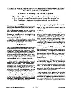
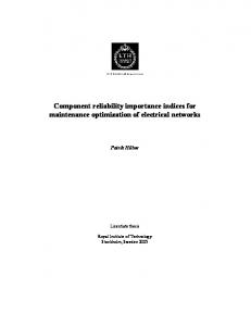
The behaviour of the system with an optimal parameter set is shown in Figs 8 10. In Fig. 8. the response of the motor is shown, in Fig. 9 the displacement of the pump and the valve is shown. The pressure responses can be seen in Fig 10 where also the total energy consumtion is displayed. The optimized system is highly nonlinear with saturated pump and valve in most of the transient phase. This is in order to keep component cost low by making them small. The controller used here was very simple being a pure position feedback. The main object for this optimization was, however, not to optimize a controI system but rather to optimize the sizes of the components involved. The gain had to be included as an independent variable because the system had to be controlled during the optimization. The cost function on the pumps can cause either one or two pumps to be optimal. This is determined by the exponent "'sp- Usually "'sp is less than one for small sizes, while it becomes larger than one for large sizes. In the example shown here a fixed value of "'sp = 0.5 was used and the result can be observed here since one of the two pumps is reduced to a very small value (0.036 compared to 0.6 for the other pump). The number of simulations needed to reach optimum was 308 but a system with decent performance was obtained in just a fraction of that time, since all parameters except the pressure level and the distribution of pump sizes has been found after about 150 simulations. The simulation time for each simulation was about 5.6 sec. The whole optimization the took about 29 minutes which is very reasonable. Still there is a great potential for improvements. Variable time step would easely reduce the time by at least a factor 2. This means that a complete optimization can be performed in less time than one simulation took just a few years ago.
DISCUSSION An alternative to the use of the scaling factor s is to use interpolation between datafiles. If they are ordered with respect to size most parameters of a component would be monotonous function of the order number. This has the advantage that the optimization results can be translated directly into a set of existing components. There are, however, situations when size alone is unsufficient, as a performance parameter for a component. There may also be parameters that determine the performance in other respects, eg there may be servo valves and proportional val ves of the same size hut of different responses and this property suggests that some components need more than one performance parameter to be specified. Still, the number of independent variables is small compared to the total number of local parameters in the components. To increase the speed of the optimization, the Complex algorithm could be modified in order to take advantage of the possibilty of making several simulations in paralleI. Other optimization algorithms have also yet to be tested. One inter11
esting method has been used in the DSH package [2]. This method is based on evolution strategy for biological systems, a concept descibed by Rechenberg [6].
CONCLUSIONS Advancements in both software and hardware in recent years are so great that the hund reds of simulations required for system optimization can be performed in about the same time it took to make one simulation a few years ago. In this pape it has been shown how optimization can be used for component selection in a hydraulic system. It has also been demostrated how redundant components are eliminated automatically by the optimization process, reducing there size to near zero. This indicates that optimization, to some extent, also can be used to determine the system layout. The basic assumtion for the optimization is that all important parameters of a component can be expressed as monotonus functions of a set of very few performance parameters eg the size of a component. This means that the number of independent variables for the optimization is limited which leads to reasonable numbers of iterations. Still, optimization requires a substantial number of simulations to be performed and consequently it is important to have very effective simulation methods. Here, the IPM method has been used here which leads to very reasonable simulation times.
12
REFERENCES
[l] M. J. Box. A new method of constrained optimization and a comparison with other methods. Computer Journal, 8:42-52, 1965. [2] Institut Fur Hydraulische Antriebe und Steuerungen IHP, RWTH Aachen . DSH Benutzer handbuch, 1980. [3] P. Krus, A. Jansson, and J.-O. Palmberg. Real-time simulation of hydrauli c control systems with complex mechanical loads. In 5th IFACjIMACS Symposium on Computer Aided Design in ControI Systems, CADCS 91, Swansea, UK, 1991. IFAC. [4] P. Krus, A. Jansson, J .-0. Palmberg, and K. Weddfelt. Distributed simulation of hydromechanical systems. In Third Bath International Fluid Power Workshop', Bath, UK, 1990. [5] T. Nakada. Range of controi for electrohydraulic servovalves represented by the rate of flow and the frequency characteristics. In International Symposium on Fluid Contral and Measurement, FLUCOME, pages 421-427, Tokyo, Japan , 1985. [6] L Rechenberg. Evolutionsstrategie - Optimierung technischer Systeme nach Prinzipien der biologischen Evolution. Friedrich Frommann Verlag, 1973.
[7] J. Roth.
Regelkonzept fur lagegeregelte elektrohydraulische servoantriebe. Ö/hydraulik und Pneumatik, (8):537-541, 1983.
[8] K.-E. Rydberg. On Performance Optimization and Digital Controloj Hydrostatic Drives for Vehicle Applications. PhD thesis, Linköping University, S-58183 Linköping, 1983. [9] W. E. Wilson. Performance criteria for positive displacement pumps and fluid motors. In ASME Semi.Annual Meeting. ASME, 1948.
13