Optimization of a continuous phase-only sampling for high channel–count fiber Bragg gratings Hongpu Li1, Ming Li1, Kazuhiko Ogusu1, Yunlong Sheng2, and Joshua E. Rothenberg3 1
Department of Electrical and Electronic Engineering, Shizuoka University, 3-5-1, Johoku, Hamamatsu, 432-8561, Japan
[email protected]
2
Department of Physics, Physics Engineering, and Optics, Center for Optics, Photonics, and Laser, Laval University, Quebec G1K7P4, Canada 3
Northrop Grumman Space Technology, Redondo Beach, CA 90278, U.S.A
Abstract: A novel continuous phase-only sampling function capable of producing up to 81-channel FBG with excellent channel uniformity and high in-band energy efficiency is presented and optimized by using the simulated annealing algorithm. In order to fabricate this kind of FBGs with a conventional side-writing phase-mask technique, both the diffraction effects and fabrication tolerance of the phase-shifted phase mask have also been addressed. Compared with the numerical results, a 45-channel (spacing of 100 GHz) and an 81-channel (spacing of 50 GHz) phase-only sampled linearly chirped FBG are successfully demonstrated. © 2006 Optical Society of America OCIS codes: (230.1480) Bragg reflectors; (050.5080) Phase shift; (050.2770) Grating; (060.2340) Fiber optics components
References and links 1. 2. 3. 4. 5. 6. 7. 8. 9. 10. 11. 12. 13.
F. Ouellette, P. A. Krug, T. Stephens, G. Dhosi, and B. Eggleton, “Broadband and WDM dispersion compensation using chirped sampled fibre Bragg gratings,” Electron. Lett. 30, 899-901(1995). Z. Pan, Y. W. Song, C. Yu, Y. Wang, Q. Yu, J. Popelek, H. Li, Y. Li, and A. E. Willner,“Tunable chromatic dispersion compensation in 40-Gb/s systems using nonlinearly chirped Fiber Bragg Gratings,” J. Lightwave Technol. 20, 2239-2246 (2002). B. Eggleton, P. A. Krug, L. Poladian, and F. Oullette, “Long periodic superstructure Bragg gratings in optical fibres,” Electron. Lett. 30, 1620-1622 (1994). M. Durkin, M. Ibsen, M. J. Cole, and R. I. Laming, “1 m long continuously-written fibre Bragg gratings for combined second-and third-order dispersion compensation,” Electron. Lett. 33, 1891-1893 (1997). Y. Painchaud, A. Mailoux, H. Chotard, E. Pelletier, and M. Guy, “Multi-channel fiber Bragg gratings for dispersion and slope compensation,” in Proc. Optical Fiber Communication Conference (Optical Society of America, Washington, D.C., 2002), paper ThAA5. M. Morin, M. Poulin, A. Mailloux, F. Trepanier, and Y. Painchaud, “Full C-band slope-matched dispersion compensation based on a phase sampled Bragg grating,” in Proc. Optical Fiber Communication Conference (Optical Society of America, Washington, D.C., 2004), paper WK1. M. Ibsen, M. K. Durkin, M. J. Cole, and R. I. Laming, “Sinc-sampled fiber Bragg gratings for identical multiple wavelength operation,” IEEE Photon. Technol. Lett. 10, 842-844 (1998). W. H. Loh, F. Q. Zhou, and J. J. Pan, “Sampled fiber grating based-dispersion slope compensator,” IEEE Photon. Technol. Lett. 11, 1280-1282 (1999). A. V. Buryak K. Y. Kolossovski, and D. Y. Stepanov, “Optimization of refractive index sampling for multichannel fiber Bragg gratings,” IEEE J. Quantum Electron. 39, 91-98 (2003). J. E. Rothenberg, H. Li, Y. Li, J. Popelek, Y. Sheng, Y. Wang, R. B. Wilcox, and J. Zweiback, “Dammann fiber Bragg gratings and phase-only sampling for high channel counts,” IEEE Photon. Technol. Lett. 14, 1309-1311(2002). H. Li, Y. Sheng, Y. Li, J. E. Rothenberg, “Phased-only sampled fiber Bragg gratings for high channel counts chromatic dispersion compensation,” J. Lightwave Technol. 21, 2074-2083 (2003). H. Lee and G. P. Agrawal, “Purely phase-sampled fiber Bagg gratings for broad-band dispersion and dispersion slope compensation,” IEEE Photon. Technol. Lett. 15, 1091-1093 (2003). V. Jayaraman, Z. M. Chuang, and L. A. Coldren, “Theory, design, and performance of extended tuning semiconductor lasers with sampled gratings,” IEEE J. Quantum Electron. 29, 1824-1834 (1993).
#68690 - $15.00 USD
(C) 2006 OSA
Received 6 March 2006; revised 6 April 2006; accepted 7 April 2006
17 April 2006 / Vol. 14, No. 8 / OPTICS EXPRESS 3152
14. H. Ishii, Y. Tohmori, T. Tamamrua, and Y. Yoshikuni, “Super structure grating (SSG) lasers for broadly tunable DBR lasers,” IEEE Photon. Technol. Lett. 4, 393-395 (1993). 15. R. Kashyap, Fiber Bragg Grating (Academic, San Diego, 1999). 16. L. Poladian, B. Ashton and W. Ppadden, “Interactive design and fabrication of complex FBGs,” in Proc. Optical Fiber Communication Conference (Optical Society of America, Washington, D.C., 2003), paper WL1. 17. Y. Sheng, J. E. Rothenberg, H. Li, Y. Wang, and J. Zweiback, “Split of phase-shifts in phase mask for fiber Bragg grating,” IEEE Photon. Technol. Lett. 16, 1316-1318 (2004). 18. J. E. Rothenberg, H. Li, J. Popelek, J. Zweiback, and Y. Sheng, “A novel phase-only sampled 45-channel fiber Bragg grating written with a diffraction-compensated phase mask,” Opt. Lett. (to be published). 19. Y. Sheng and L. Sun, “Near-field diffraction of irregular phase gratings with multiple phase-shifts,” Opt. Express 13, 6111-6116 (2005). 20. J. Skaar, L. Wang, and T. Erdogan, “On the synthesis of fiber Bragg grating by layer peeling,” IEEE J. Quantum Electron. 37, 165-173 (2001). 21. K.-M. Feng, S. Lee, R. Khosravani, S. S. Havstad, and J. E. Rothenberg, “45 ITU-100 channels dispersion compensation using cascaded full C-band sampled FBGs for transmission over 640-Km SMF,” in Proc. Eur. Conf. Optical Communication (ECOC2003), paper Mo.3.2.5.
1. Introduction Recently high channel-count fiber Bragg grating (FBG), as one of the fiber-based promising solutions to the broad-band chromatic dispersion compensation for the existing fiber link, has attracted great interests [1-12]. However, with an increasing number of wavelength-divisionmultiplex(WDM) channels to cover the full C-band, high channel-count FBG devices become extremely difficult to realize due to the requirements of a considerably high index-modulation and the tremendous precision of the FBG writing tools. To date, three main methods have been proposed trying to make FBG based broad-band devices realizable. One is the utilization of a long-length fiber as reported in [4], where a nonlinearly chirped FBG was demonstrated as a simultaneously chromatic dispersion and slope dispersion compensator, but the grating length is 1 meter too long to be used in a practical system due to the effects of the package, temperature and uniformity. The second one is to overwrite the gratings with different central wavelengths in a same length of fiber [5], but exact matching the channel central wavelengths to the ITU grids is a challenge, and the writing time for a high channel-count FBG is too long to be acceptable. The third one is the utilization of various advanced sampling functions [714] to construct a multiple identical FBG in a same length of fiber as that of one-channel FBG. Of all the sampling methods, the phase-only sampling seems to be the most prospective one, because it can deduce the index change required for a 40- or 80-channel sampled FBGs to a practical levels [10, 11]. Furthermore, phase-only sampling has no modulation in its amplitude such that the apodization profile for a multi-channel FBG is the same as that of the seed grating, which thus makes the multi-channel gratings particularly suitable to be fabricated with the robust side-writing phase-mask technique. However, how to exactly write a varying sampling-phase in the profile of the FBG has been a critical issue in the practical processes. For a discrete phase-only sampling function, each period is divided into a number of discrete steps such that one can insert these phase steps into the profile of the seed grating directly by using the phase-shifted mask technique [15]. Although the phase-shifts can be imprinted into the FBGs by adjusting the relative transverse moving between fiber and the interference fringes in a direct writing system or by wiggling the phase mask in a scanning-writing system [16], the phase-shifted phase mask approach has advantages over the others since the phase shift is directly fabricated in an ebeam phase mask with very high accuracy and it has already been used to write a multichannel FBG with 5-9 channel [11, 17]. With increasing the number of channels up to 80 to cover full C-band (4THz), optimization for the discrete sampling function becomes too difficult to be realized, a continuous phase-only sampling (with it the phase profile can simply be encoded into every period of the seed grating by using the advanced stitch-error-free lithography mask) is strongly desired [18]. Furthermore, when a phase-shifted mask is used to write a grating, it was general considered that the phase-shifts in the phase-mask were completely replicated in the FBG [15]. #68690 - $15.00 USD
(C) 2006 OSA
Received 6 March 2006; revised 6 April 2006; accepted 7 April 2006
17 April 2006 / Vol. 14, No. 8 / OPTICS EXPRESS 3153
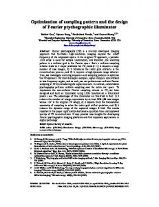
However it is only correct when the distance between the mask and the fiber core is zero [19]. Due to the minimum spacing between the phase mask and the fiber core, which is the radius of the fiber cladding, the phase shift in mask is not replicated into the FBG but is split into two two-half amplitude phase-shifts, which are separated by a transverse distance between the +1 and -1 diffracted order. The split of the phase-shifts in the phase mask does occur not only for a single phase-step, but also for multiple phase-steps, which could be crossover one another. As a result, the phase information that is written into the mask is distorted when it is transferred to a piece of fiber core by proximity printing, which thus makes the channelchannel uniformity considerably distorted. In this paper, a novel continuous phase-only sampling function is presented, where considerations and tolerance of the diffraction effects of the phase shifts have been taken into account. Optimization for 25-, 45-, and 81-channel phase-only sampling function with excellent channel uniformity and high in-band energy efficiency is carried out with using the simulated annealing algorithm. Finally, a 45-channel (spacing of 100 GHz) and 81-channel (spacing 50 of GHz) phase-only sampled FBG are demonstrated compared with the numerical results. 2. Theory of the diffraction compensation phase-mask for side-writing of FBG It is known that phase steps are necessary in the phase-only sampled FBG, which introduce phase shifts in the profile of FBG. The phase-shifted phase-mask used for the fabrication of FBG is generally a surface relief binary phase grating with rectangle profile, where phasesteps θ m are inserted at certain locations as shown in Fig. 1. The diffraction of the incident UV light incident on the mask splits into two at angles of ±ϕ 0 . Their separation in the fiber core at a distance of z from the mask is Δx = 2 z tan ϕ 0 . Base on the fact that the phase in the mask will be split into two two-half amplitude phase-shifts separated with a lateral distance between the +1 and -1 diffracted light [19], the relation between the phase in the mask and the resulted phase θ g (x) in the fiber core is expressed as
θ g ( x) = θ m ( x) ⊗ [δ ( x − Δx / 2) + δ ( x + Δx / 2)] ,
(1)
where ⊗ represents the convolution. Taking the Fourier transform to Eq. (1), one obtains the phase frequency transfer function as ~
~
θ g ( f ) = 2 cos(πfΔx)θ m ( f ) , x=0 Phase mask
Phase shift θ
m
(2)
(x) x
z=0 -1 order
z
ϕ0
+1 order
Phase shift θ
g
(x)
Fiber Core
Δx = 2 z tanϕ 0
Fig. 1 . Diffraction geometry of the phase-shifted phase mask.
~ ~ where θ g and θ m are Fourier transforms the phase profiles and f is the spatial frequency of
the mask. Assuming that both θ g ( x ) and θ m ( x) are changed periodically with period P , the #68690 - $15.00 USD
(C) 2006 OSA
Received 6 March 2006; revised 6 April 2006; accepted 7 April 2006
17 April 2006 / Vol. 14, No. 8 / OPTICS EXPRESS 3154
spatial frequency f is then in the unit of 1 / P , and the channel frequency spacing in FBG is given by Δν = c /(2n group P) . Equation (2) shows that the diffraction effect can cause very sever distortion for large magnitude f and made the grating phase vanishes at f = 1 / (2Δx ) . Now we propose one method for designing a mask to compensate for the diffractive propagation effects to the fiber core. We simply solve Eq. (2) for the mask phase ~
~
θ m ( f ) = θ g ( f ) / 2 cos(πfΔx) ,
(3)
then the pre-compensation processes can be described in the following. First, we calculate the ~ Fourier transform of the desired FBG phase θ g , use Eq. (3) to find the spatial spectrum of the mask phase, and then transform it back to find the phase function in mask. Finally, with this diffraction-compensated phase mask, we can exactly imprint the sampling-phase θ g (x) in the profile of the FBG rather than the distorted one. Note that this compensated method is not suitable for any binary or multi-levels phase-only sampling functions [11] because of the existence of infinite spatial-frequency terms. Another limitation for this method is that the phase-sampling functions should be the one where its spatial frequencies is not too close to f = 1 / (2Δx ) , otherwise it would be divided by a small number in Eq. (3) which would lead to inaccurate or unphysical results. 3. A continuous phase-only sampling for high channel-count FBG 3.1. Phase-only sampling function with diffraction compensation Sampling method is widely used to realize a multi-channel FBG in a limited length of photosensitive fiber. In a sampled FBG, the induced refractive index modulation Δn can be expressed as
Δn(x ) = Re{(Δn1 ( x ) / 2) ⋅ exp(i(2πx / Λ + φ g ( x ))) ⋅ s( x )} ,
(4)
where Δn1 ( x) is the maximum index modulation, x is the position along the grating, Λ is the central pitch of the grating, φ g (x) is the local phase for one channel grating which determines
the dispersion of the grating. s (x ) stands for a sampling function with period P. Next, we consider the phase-only sampling function. As usual, we write the sampling function s (x ) with a period P as s ( x ) = sb ( x ) ⊗
∑δ (x − mP) ,
(5)
m
where sb ( x ) is the base sampling function in one period. In general, the base sampling function sb ( x ) discussed [10-11] is given as a discrete one. As matter of fact, it could be a continuous one with the analytical form: sb ( x) = exp[iθ g ( x)] .
(6)
We assume that θ g ( x) has the general form including more harmonic terms as:
θ g ( x) =
#68690 - $15.00 USD
(C) 2006 OSA
∑
M
n =1
α n cos(2πnx / P + β n ) ,
(7)
Received 6 March 2006; revised 6 April 2006; accepted 7 April 2006
17 April 2006 / Vol. 14, No. 8 / OPTICS EXPRESS 3155
where the number of terms M is minimized, α n and β n are optimized such that the channel spectrum is flat within the band of interest. Considering the diffraction effect, the precompensated phase of the phase mask according to Eq. (3) is then obtained
θ m ( x) =
∑
αn
M n =1
2 cos(πnΔx / P)
cos(2πnx / P + β n ) .
(8)
When the diffraction effect is not taken into account for the design of the phase-mask, the grating phase becomes
θ gR ( x) =
∑
M n =1
α n cos(2πnx / P + β n ) ⋅ cos(πnΔx / P ) .
(9)
3.2 Optimization of the phase-only sampling function with simulated annealing algorithm In Eq. (7), one would generally assume that at least 2M uniform channels could be achieved with M terms in this series since there are two free parameters for each term. In order to obtain optimal magnitudes of the series of α n , β n , we exploit the simulated annealing algorithm, where the optimization criteria are the uniformity of the desired channels and the diffraction efficiency η [11]. Simulated annealing is a recursive Metropolis algorithm to reduce a cost function with a progressively decreasing control parameter called temperature T. The cost function is defined as E ( x) =
∑ N
−N
⎡ S (α , α , ⎢ m 1 2 ⎣
α M , β1 , β 2 ,
, βM ) − 2
η 2N
⎤ + 1⎥⎦
2
,
(10)
where S m is the mth Fourier coefficient of the base sampling function sb (x) , η ( 0 the new α n , β n will still be accepted with a probability h(ΔEk ) = exp(− ΔE k / T ) .
(11)
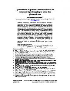
The simulated annealing algorithm is based on an analogy with statistical mechanics, which is often used to obtain a globally optimal solution for a nonlinear process with multi-variable parameters. A number of designs were completed for the above continuous phase-only sampling function. The optimal results for a 25-, 45-, and 81-channels are shown in Fig. 2, Fig. 3 and Fig. 4, respectively, where the original phase profile (Eq. (7)) and the phase profiles under the diffraction effect (Eq. (9)) are both shown in Figs. (a), and correspondence of the two Fourier spectra are shown in Figs. (c), and (d), respectively. The spacing between the mask and the written fiber is assumed to be z = 10 μm. Considering the refraction happened in the fiber cladding (for cladding index of 1.45) and the radius of cladding, we have Δx = 25 μm. For convenience, the period of the sampling function is normalized to one. In order to obtain the
#68690 - $15.00 USD
(C) 2006 OSA
Received 6 March 2006; revised 6 April 2006; accepted 7 April 2006
17 April 2006 / Vol. 14, No. 8 / OPTICS EXPRESS 3156
Original design Without compensation
(a)
1 0 -1 -2 0.0
0.2
0.4
0.6
0.8
Fourier transform of exp(iθ(z))
(b) 0.20 0.15 0.10 0.05 0.00
1.0
-20
0
Position
Fourier transform of exp(iθ(z))
0.4
Spectrum amplitude
0.25
2
Spectrum amplitude
Phase
( in unit of π )
high diffraction efficiency η , 13, 23, and 41 harmonic terms were selected for 25-, 45-, and 81-channel, respectively. It can be seen that the original sampling design are pretty reasonable. The diffraction efficiencies obtained with the simulated annealing algorithm are 92%, 92% and 84%, respectively. Non-uniformity of the channel intensities are 0.1%, 0.8% and 1.0%, respectively. However, with the phase-split effect due to the mask diffraction, the resulted channels are considerably distorted (as shown in Fig. 2(c), Fig. 3(c), and Fig. 4(c)), which in return means that the compensation to the diffraction effect is necessary once a sampled FBG with high channel-count is written with the side-writing technique.
(c) 0.3 0.2 0.1 0.0
20
-20
0
20
Channel
Channel
Original design Without compensation
(a)
2 0 -2 -4 0.0
0.2
0.4
0.6
0.8
(b) 0.15 0.10 0.05 0.00
1.0
Fourier transform of exp(iθ(z))
-40
-20
Position
0
20
Fourier transform of exp(iθ(z))
0.3
Spectrum amplitude
0.20
4
Spectrum amplitude
Phase
( in unit of π )
Fig. 2. 25-channel continuous phase-only sampling functions and their FFT spectra. (a) Phase functions with and without the diffraction effect, (b) spectrum without the diffraction, and (c) spectrum with the diffraction effect.
(c) 0.2
0.1
0.0 -40
40
-20
0
20
40
Channel
Channel
(a)
1 0 -1 -2 0.0
Fourier transform of exp(iθ(z))
0.15 Original design Without compensation
0.2
0.4
0.6
Position
0.8
1.0
0.4
(b)
Spectrum amplitude
2
Spectrum amplitude
Phase
( in unit of π )
Fig. 3. 45-channel continuous phase-only sampling functions and their FFT spectra. (a) Phase functions with and without the diffraction effect, (b) spectrum without the diffraction, and (c) spectrum with the diffraction effect.
0.10
0.05
0.00 -80
-40
0
Channel
40
80
Fourier transform of exp(iθ(z))
(c) 0.3 0.2 0.1 0.0 -80
-40
0
40
80
Channel
Fig. 4. 81-channel continuous phase-only sampling functions and their FFT spectra. (a) Phase functions with and without the diffraction effect, (b) spectrum without the diffraction, and (c) spectrum with the diffraction effect.
#68690 - $15.00 USD
(C) 2006 OSA
Received 6 March 2006; revised 6 April 2006; accepted 7 April 2006
17 April 2006 / Vol. 14, No. 8 / OPTICS EXPRESS 3157
To verify the accomplished designs, the sampling functions were multiplied by a single channel FBG, which can be obtained by using the layer peeling method [20]. The reflection spectrum of the sampled FBG was computed with the transfer matrix method. The results for a linear chirped 45-channel with spacing 100 GHz, chromatic dispersion -1360 ps/nm and an 81-channel with spacing 50 GHz are shown in Figs. 5 and 6, respectively. The reflection spectra show high intra- and inter-channel uniformity within nearly whole C-band.
-10 -20 -30
(b) 800
-10 600 -20 400 -30
200
-40 1544.6
-40 1520 1530 1540 1550 1560 1570
1544.8 1545.0
Group delay (ps)
Reflection (dB)
Reflection (dB)
1000
0
(a)
0
0 1545.2 1545.4
Wavelength (nm)
Wavelength (nm)
Fig. 5. Calculated results for the sampled 45-channel FBG (channel spacing of 100 GHz). (a) Reflection spectrum for all 45 channels, (b) reflection and group delay spectra at the central channel.
Reflection (dB)
Reflection (dB)
(b)
0
-10 -20 -30
1000 800
-10
600
-20
400
-30
200
-40 1520 1530 1540 1550 1560 1570
0 -40 1544.6 1544.8 1545.0 1545.2 1545.4
Wavelength (nm)
Wavelength (nm)
Group delay (ps)
(a)
0
Fig. 6. Calculated results for the sampled 81-channel FBG (channel spacing of 50 GHz). (a) Reflection spectrum for all 81 channels, (b) reflection and group delay spectra at the central region.
Note that, all the above results are based on the assumption that the separation between the mask and the fiber is z = 10 μm . However, in the practical fabrication, it is strongly desired to know in what extent the deviation of this separation could be allowable. We then investigated the effect of the spacing deviation on the inter-channel uniformity by following equation:
θ gR ( x) =
∑
cos(πnΔx R / P) ⋅ α n cos(2πnx / P + β n ) , n =1 cos(πnΔx / P) M
(12)
where Δx R is the actual lateral distance between the +1 diffraction and –1 diffraction light at the fiber. Δx ( = 25 μm ) is the nominal one for spacing z = 10 μm . θ gR is the resulted phase profile in a fiber core where a deviation to the nominal spacing is introduced. For convenience, the 45-channel phase-only sampling function shown in Fig. 3 was investigated. The simulation results are shown in Fig. 7. Compared with the original results shown in Fig. 3, it is found that #68690 - $15.00 USD
(C) 2006 OSA
Received 6 March 2006; revised 6 April 2006; accepted 7 April 2006
17 April 2006 / Vol. 14, No. 8 / OPTICS EXPRESS 3158
the channel uniformity depends strongly on the magnitude of the spacing deviation, the nonuniformity of the channel intensities become 5%, 15%, and 22% when the deviation is ±1 , ±3 , and ±5 μm respectively. In order to remain high channel-channel uniformity, it is known that precision of ±1 μm for the spacing is expected while the side-writing technique is used.
0.20
0.25
(a)
Theoretical Devitation with 1μm Devitation with -1μm
0.15 0.10 0.05 0.00
-40
-20
0
20
(b)
Theoretical Devitation with 3μm Devitation with -3μ m
0.20 0.15 0.10 0.05 0.00
40
Fourier transform of exp(iθ(z))
-40
-20
Channel
0
20
0.25
Spectrum amplitude
Fourier transform of exp(iθ(z))
Spectrum amplitude
Spectrum amplitude
0.25
40
Channel
Fourier transform of exp(iθ(z))
(c)
Theoretical Devitation with 5μm Devitation with -5μ m
0.20 0.15 0.10 0.05 0.00
-40
-20
0
20
40
Channel
Fig. 7. FFT spectra for a 45-channel continuous phase-only sampling function, where the deviation to the spacing (10 μm) between the mask and the fiber are (a) ± 1 μm (b) ± 3 μm , and (c) ± 5 μm.
4. Experimental results
Next, the obtained diffraction-compensated phase function θ m ( x) (as shown in Eq. (8)) and the phase φ g ( x) for one seed grating (shown in Eq. (4)) with dispersion of -1360 ps/ns were encoded into the grating, whose local period becomes
Λ
M
( x) ≈ 2
(Λ + (1 2π ) ⋅ d Φ (x ) d x ) , −1
(13)
where Λ is the central pitch and Φ ( x) = θ m ( x) + φ g ( x) is the local phase. There are two
approaches to implement Λ M ( x ) . Ideally, one can change every period of the grating. In this case, the phase mask must be written with the required accuracy and written continuously without stitching. One can also divide the entire grating into a large number of steps. Each step is considered as a uniform grating with the local average period Λ M ( x ) . We used the former approach. The phase mask is designed and fabricated with a special “stitch-error-free” lithography tool. The sampled FBG was written with side-writing technique [11, 18]. To confirm our numerical results, several 45-channel and 81-channel FBGs were fabricated. Figure 8 shows the measured results of one typical FBG with 45-channel, where the grating length is 10 cm and the peak index-modulation required is about 5.6×10⁻⁴. It can be seen that nearly identical 45 channel with a channel spacing of 100 GHz, useable bandwidth of 0.21 nm, peak-peak group-delay near 20 ps, and chromatic dispersion of about –1374 ps/nm have been obtained. These results agree well with our design data. Noted that this kind of high-quality high channel-count FBG has already been successful used as a dispersion compensator through full C-band for transmission over 640-km SMF fiber [21]. Figure 9 shows the measured results of one typical FBG with 81-channel, where the grating length is 10 cm also and the peak index-modulation required is about 8 × 10⁻⁴. It can also be seen that nearly identical 81 channel with a channel spacing of 50 GHz, useable bandwidth of 0.11 nm, and chromatic dispersion of about –1400 ps/nm have been obtained. Although the group delay ripple shown in Fig. 9(b) is a little bit large and the inter-channel uniformity is worse than that of 45-channel FBG shown in Fig. 8(b), which is most probably due to the demands of higher index-modulation and more strict precision control for the spacing between the mask and the
#68690 - $15.00 USD
(C) 2006 OSA
Received 6 March 2006; revised 6 April 2006; accepted 7 April 2006
17 April 2006 / Vol. 14, No. 8 / OPTICS EXPRESS 3159
fiber, this is the first reported for a sampled FBG with up to 81 channels and these results verify that the proposed continuous sampling with pre-diffraction compensation is reasonable.
-10 -20 -30 -40
-10
800
-20
600
-30
400
-40 1530
1540
1550
1000
(b)
1560
1543.6 1543.8 1544.0 1544.2
Group delay (ps)
0
(a) Reflection (dB)
Reflection (dB)
0
200
Wavelength (nm)
Wavelength (nm)
Fig. 8. Experimental results for a fabricated 45-channel linearly chirped FBG. (a) Reflection spectrum for all 45-channel, (b) reflection and group delay spectra at the central channel.
-20 -30 -40
1530
1540
1550
Wavelength (nm)
1560
(b) 800
-10 600 -20
400
Group delay (ps)
-10
1000
0
(a) Reflection (dB)
Reflection (dB)
0
-30 200 1543.4 1543.6 1543.8 1544.0 1544.2
Wavelength (nm)
Fig. 9. Experimental results for a fabricated 81-channel (spacing 50 GHz) linearly chirped FBG. (a) Reflection spectrum for all 81-channel, (b) reflection and group delay spectra at the central two channels.
4.
Conclusion
A novel continuous phase-only sampling function has been proposed, where both the diffraction effects of the phase-shifted mask and the fabrication tolerance have been considered. Optimization for a 45- and an 81-channel sampling function with excellent channel uniformity and high in-band energy efficiency has been carried out with utilization of the simulated annealing algorithm. Finally, a 45-channel (spacing of 100 GHz) and 81-channel (spacing of 50 GHz) FBG for nearly whole C-band dispersion compensation have been demonstrated. The measured results for the fabricated FBGs agree well with the theoretical ones. Acknowledgments
H. Li acknowledges the financial supports from the Research Foundation for the Electrotechnology of Chubu (REFEC) and the Support Center for Advanced Telecommunications Technology Research (SCAT) in Japan.
#68690 - $15.00 USD
(C) 2006 OSA
Received 6 March 2006; revised 6 April 2006; accepted 7 April 2006
17 April 2006 / Vol. 14, No. 8 / OPTICS EXPRESS 3160