Sensors 2009, 9, 2076-2087; doi:10.3390/s90302076 OPEN ACCESS
sensors ISSN 1424-8220 www.mdpi.com/journal/sensors Article
Optimization of a PVC Membrane for Reference Field Effect Transistors Chao-Sung Lai 1,*, Cheng-En Lue 1, Chia-Ming Yang 2, Marek Dawgul 3 and Dorota G. Pijanowska 3 1
2
3
Department of Electronic Engineering in Chang Gung University. / 259 Wen-Hwa 1st Road, KweiShan, Tao-Yuan, R.O.C., Taiwan, 333 Device Section, Department of WAT and Devices, Inotera Memories Inc. / 667, Fuhsing 3rd Road, Hwa-Ya Technology Park, Kwei-Shan, Tao-Yuan, Taiwan Institute of Biocybernetics and Biomedical Engineering, Polish Academy of Sciences / ul. Trojdena 4, 02-109 Warsaw, Poland.
* Author to whom correspondence should be addressed; E-Mail:
[email protected]; Tel.: +886-3-2118800 ext.5786; Fax: +886-3-2118507 Received: 20 February 2009; in revised form: 9 March 2009 / Accepted: 12 March 2009 / Published: 19 March 2009
Abstract: For the miniaturization of ISFET sensing systems, the concept of a REFET with low ion sensitivity is proposed to replace the conventional reference electrodes through the arrangement of a quasi reference electrode and a differential readout circuit. In this study, an ion-unblocking membrane was used as the top layer of a REFET. To optimize the REFET performance, the influences of the silylating process, different plasticizers, and the composition of the PVC cocktails were investigated. A low sensitivity (10.4 ± 2.2 mV/pH) and high linearity (99.7 ± 0.3 %) in the range from pH 2.2 to pH 11.6 was obtained for the REFET with a 60 wt.% DNP/(DNP + PVC) membrane. To evaluate the long term stability, the drift coefficient was estimated, and for the best REFET, it was –0.74 mV/h. Two criteria for assessing the lifetime of REFETs were used, namely the increase in pH sensitivity to a value higher than 15 mV/pH and the degradation of linearity below 99 %. For the best REFET, it was approximately 15 days. Keywords: PVC membranes; ion-unblocking membranes; REFET, silylating; plasticizers.
Sensors 2009, 9
2077
1. Introduction The ion sensitive field effect transistor (ISFET) was first proposed by P. Bergveld in 1970 [1]. Because the device structure and fabrication process are similar for metal oxide field effect transistors (MOSFETs) and ISFETs, both devices can easily be manufactured by CMOS technology and miniaturized to the micrometer scale [2]. In addition, high bio-compatibility and fast responses have led many researchers to investigate ISFETs as platforms for sensing clinically important species, such as penicillin, urea, glucose, creatinine, etc. [3-7]. Based on these advantages, it has been concluded that ISFETs show high potential for application in “home-care” systems and continuous in-vivo monitoring [8]. However, for the purpose of ISFET sensor systems miniaturization, a critical issue for the micro reference electrode (RE) must first be solved [9,10]. To provide a stable reference potential, conventional REs, such as Ag/AgCl or calomel electrodes, filled with an internal electrolyte are used. From the state-of-the-art analysis results, the short lifetime of miniaturized REs with small internal electrolyte volume must still be improved [11,12]. To solve this problem, the concept of a differential system with an ISFET/REFET (reference field effect transistor) pair was first introduced by Matsuo in 1978 [13]. In a REFET, the surface of the sensing membrane for the ISFET was essentially chemically inactivated in order to decrease the pH sensitivity. To replace a conventional RE, an ISFET/REFET pair with a quasi reference electrode (qRE) made of a noble metal, such as Pt or Au, can be used. The output signal of the system, Vout, obtained in a differential system where VGS of the ISFET (VISFET) and of the REFET (VREFET) are both measured versus the common qRE, is as follows:
Vout VISFET VREFET
(1)
In this case, the unstable potential of the Pt/solution interface does not influence the output signal, since it is compensated in the differential readout circuit. The concept of an ISFET/REFET differential pair is not only applicable to pH sensing applications, but also to monitoring concentrations of other ions, such as Na+ and K+ [14], as well as other species, such as creatinine and urea, with the use of chemically and enzymatically modified field effect transistors (ChemFET, EnFET, respectively) [15,16]. Research on REFETs has been based on several approaches, including chemical surface modification, an additional ion-blocking layer, and an ion-unblocking layer deposition. In the first approach, which is based on chemical modification, the surface of the sensing membrane of the ISFET is inactivated by blocking the binding sites. In the case of ion-blocking layer deposition, an extra polymeric layer is cast on the surface of the ISFET. However, the first two methods cause some chemical and electrical problems, as described by Bergveld et al. [9]. Their comments imply that an additional ion-unblocking layer with a low conductivity and cation perm-selectivity would be a better solution. A polyvinyl chloride (PVC) membrane has been used to form the ion-unblocking layer on a Si3N4-ISFET [17]. The pH sensitivity of the REFET decreased to 1.8 mV/pH in the range from pH 2 to pH 9. This indicates that an ion-unblocking layer made by a PVC cocktail might be a good choice for REFET applications, since a reduced sensitivity to hydrogen ions for the REFET and a similar transconductance value for both the ISFET and REFET were obtained. However, the PVC-REFET still
Sensors 2009, 9
2078
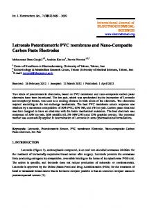
has some drawbacks, such as a small operation range, short lifetime, and high drift, which must be improved. Some methods have already been tested [17-19], such as modification of the membrane composition by including additional lipophilic cations, and the use of a buffered poly(2-hydroxyethl methacrylate) (polyHEMA) layer at the interface between the ISFET and the PVC membrane. The polyHEMA layer is frequently used in ChemFETs to decrease the pH sensitivity [20]. To optimize the PVC-REFET in this work, silylating pre-treatment, different plasticizers, and various composition ratios of the PVC cocktail were investigated on standard Si3N4-ISFETs. To evaluate the sensing properties of REFETs, the sensitivity to hydrogen ions, transconductance compatibility, drift coefficient, and lifetime were studied. 2. Experiment 2.1. Chemicals For the silylating process, hexamethyldisilazane (HMDS, Roth, Germany) and toluene (POCh Gliwice, Poland) were used. To form the PVC membrane, high molecular weight polyvinyl chloride (PVC) was purchased from Sigma; the solvent tetrahydrofuran (THF) and three kinds of plasticizers: 2-nitrophenyl octyl ether (o-NPOE), bis(2-ethly-hexyl)sebacate (DOS), and dinonylphtalate (DNP), were obtained from Fluka. The salts in this experiment were purchased from POCh Gliwice (Poland). The phosphate buffer solutions of sodium and potassium were prepared in deionized water. The pH value of the buffer solutions were adjusted by adding 0.1 M NaOH and 0.1 M HCl solutions with autoburettes (Mettler-Toledo) and monitored by a combined pH glass electrode. 2.2. ISFET fabrication To maintain electrical isolation between sensors operating in a sensor array, the ISFETs were designed as n-channel devices embedded in p-wells. These ISFETs were fabricated at the Institute of Electron Technology (IET) in Poland. A thermally grown SiO2 layer was deposited after RCA cleaning. Afterwards, the Si3N4 layer, a sensing membrane, was deposited by low pressure chemical vapor deposition (LPCVD). The gate width and length of the transistor channel are 600 μm and 16 μm, respectively. To aid in handmade encapsulation, extended source and drain areas with contact pads located away from the gate area were designed. Finally, all ISFETs were assembled on printed circuit boards (PCB) with a silver paste (TED PELLA, Inc.) and then encapsulated with epoxy resin type adhesive JU-100 (KOKI Company Ltd.) with open windows of 3 × 3 mm2. 2.3. Optimization of the PVC cocktail for REFETs In order to decrease the pH sensitivity of the ISFET for REFET application, the PVC membranes were deposited on the open gate windows of ISFETs. The fabrication process flow for the PVC membrane is illustrated in Figure 1. First, the gate insulator surface must be cleaned with deionized water and methanol. Then, for the purpose of chemical grafting and enhancing the adhesion between the PVC membrane and the Si3N4 layer, a silylating process based on hexamethyldisilazane (HMDS)
Sensors 2009, 9
2079
deposited under different conditions is applied. Then, the PVC cocktail is cast on the Si3N4 surface of the ISFET with a micro pipette. The solvent from the PVC membrane is evaporated at room temperature overnight. Figure 1. The fabrication process flow for a REFET based on a Si3N4-ISFET.
The procedure for REFET preparation was optimized by tuning the silylating process and PVC membrane composition. The stability and adhesion of the PVC membrane depends mainly on the silylating process; therefore, four silylating processes for the Si3N4 layer with various HMDS treatments were investigated. The first samples were fabricated with a stock HMDS deposited directly and then dried at room temperature for 15 min, while the second batch of samples was baked at 120oC for 5 min. For the third method, a standard HMDS evaporation process that is used in photolithography was performed at 140oC in a vapor prime oven for 2 min. In the fourth method, HMDS diluted in toluene (ratio = 1:3) was deposited on the surface of the Si3N4 layer and then dried at room temperature for 15 min. To prepare the PVC cocktails, three kinds of plasticizers with fixed weight percentage of 70 % were used: o-NPOE, DOS, and DNP. In addition, the content of the DNP plasticizer in the PVC cocktail was varied from 50 % to 80 % by weight vs. (PVC + DNP). For each batch of the PVC cocktail, six REFET samples were prepared. The total weight of the PVC + DNP was maintained at 200 mg, and all compounds were then dissolved in 3 mL of THF. 2.4. Measurement system To investigate the output signal of the ISFETs and REFETs, a constant drain voltage-constant drain current (CVCC) circuit was adopted to measure the pH sensitivity and long term stability [21,22]. The constant drain-source current (IDS) was fixed at 250 μA, and the drain-source voltage (VDS) was set at 2.5 V. For the drift coefficient evaluation, all samples were measured in a phosphate buffer (5 mM
Sensors 2009, 9
2080
NaH2PO4, 0.1 M NaCl) solution of pH 5.7 for 12 h. To evaluate the lifetime of the REFETs, the pH sensitivity and the linearity of the sensor response were checked daily for 1 month. For detailed characterization of the current-voltage curves and transconductances (gm) of the ISFETs and REFETs, the drain-source current versus drain-source voltage (IDS-VDS) and the drain-source current versus the gate-source voltage (IDS-VGS) characteristics were measured by means of a semiconductor parameter analyzer HP 4156C. To supply a stable reference potential and to obtain the pH characteristics, a conventional Ag/AgCl reference electrode was used as a common grounded electrode in all measurements. 3. Results and Discussion To optimize the sensing properties of the REFET, the silylating process is an important step and was therefore tested first. This step is used to transform the Si3N4 surface from hydrophilic to hydrophobic and improve the adhesion between the PVC membrane and the ISFET gate material [17]. In this work, the Si3N4 surfaces of ISFETs were HMDS-silylated under various conditions before the PVC cocktails were cast. All details concerning the process and results are listed in Table 1. The first three silylating processes, based on a stock HMDS deposited under different conditions, failed in the adhesion test. In the last experiment, HMDS was dissolved in toluene to improve the wettability of the Si3N4 layer by the silylating solution; then, the samples were dried, and the solvent was evaporated at room temperature for 15 min. The best yield and highest linearity of pH response was obtained for the silylating process with a ratio of HMDS:toluene = 1:3. Table 1. Silylating process for Si3N4-ISFETs (RT = room temperature). Silylating processes HMDS, RT, 15 min HMDS, 120oC, 5 min Standard HMDS evaporation, 140oC, 2 min HMDS:toluene (1:3), RT, 15 min
Yield (%) 0 50 100 100
Linearity (%) w/o