establish the communication links through the body tissues, we adopt galvanic ... the sink (eg., node N5 to relay R distance in Fig.1.(b)), can use low Pt to ...
2015 IEEE Wireless Communications and Networking Conference (WCNC): - Track 3: Mobile and Wireless Networks
Optimization of Energy Efficient Relay Position for Galvanic Coupled Intra-body Communication Meenupriya Swaminathan, Gunar Schirner, and Kaushik R. Chowdhury, Electrical and Computer Engineering Department, Northeastern University, Boston, MA 02115, USA. E-mail:{meenu, schirner, krc}@ece.neu.edu. Abstract—Implanted medical sensors and actuators within the human body will enable remote data gathering, diagnosis, and the ability to directly control drug delivery actuators. To establish the communication links through the body tissues, we adopt galvanic coupling that uses low frequency electrical signals of weak amplitude. In this paper, we propose a topology management strategy using Weiszfeld algorithm that attempts to minimize the transmission power of the body nodes by reducing the distance from the source nodes to pick-up points or relays that gather and forward the received information. It takes into account the unique propagation model of the electrical signals within the body at various tissue layers, which is completely different from over the air RF. Our algorithm considers separately the constraints of on-skin nodes and the implanted nodes, especially in terms of minimizing the energy for the latter, which cannot be easily retrieved and re-charged. It also considers the difference in specific bandwidth requirements for the applications running within the nodes, by moving relays closer towards the high data rate demanding regions. We show that by optimizing the position of the relay node, the energy consumption can be significantly improved to extend the lifetime of the intra-body network up to several years.
I.
I NTRODUCTION
Recent developments in tiny sensor platforms have given rise to nodes that can be embedded within the body using minimally invasive procedures. These implanted sensors can potentially monitor and control various physiological processes in-situ autonomously. Hence, this technology is poised to revolutionize healthcare applications by creating a network of such connected miniature implants, which we term as an intra-body network (IBN). The IBN will allow the implants to (i) exchange information for self-configuration, and (ii) issue situation-based instructions to the drug delivery actuators without human intervention. As radio frequency (RF) waves are strongly attenuated within the body and consume more power, we adopt galvanic coupling (GC) based IBN (GC-IBN), in which a pair of electrodes within a node inject a low strength, modulated signal to the body tissue. The difference in potential created by the induced field is detected by the electrode pair of a receiver node that demodulates the signal to retrieve the data. The embedded nodes are expected to serve continuously over the application lifetime without any redundancy in their deployment. Thus, reducing the energy consumption and extending the battery life of body nodes in general, and implanted nodes in particular, are the key challenges in GC-IBN design. This paper takes the first steps towards identifying the location for the data aggregation functions, enabled by ‘relay’ nodes from a viewpoint of energy minimization and meeting application-requirements.
978-1-4799-8406-0/15/$31.00 ©2015 IEEE
1725
The potential for GC-IBN in establishing IBNs has been demonstrated using the tissue channel characterization studies in [1], [2]. However, there have been limited efforts in influencing the topology of the IBN by utilizing the channel characteristics, which are different from classical over the air RF propagation. The energy consumption in such networks depends not only on the arrangement of nodes, in terms of the relative spatial distance but also on the type of tissue and the depth within the tissue. An energy efficient network topology should minimize the path length between the transmitter and receiver (that determines the path loss) and in-turn the transmission power (P t). For instance, an implant node close to the sink (eg., node N 5 to relay R distance in Fig.1.(b)), can use low P t to communicate with the sink, while a distant node (eg., node N 2 to R link in Fig.1.(b)) requires high values of P t. In this paper, we analyze the parameters that influence the shortest path length towards extending the battery life of nodes. The main contributions of this paper are as follows: 1) We estimate the bounds on P t for each node, given the specific tissue it is embedded in, while meeting both reliability and tissue safety constraints. 2) We propose a multi-variate optimization approach based on Weiszfeld algorithm in determining the position of on-skin aggregators or relays that serve a cluster of body nodes. The proposed approach incorporates variations in the heterogeneity of data rate, the position of nodes in tissues, and the path loss of the body channel. Our objective function is designed to minimize the net signal flow through the tissues, and thereby maximize network lifetime. The paper is organized as follows. Sec.II, analyzes the related work on optimizing topology for energy efficiency. The system model is presented in Sec.III. Sec.IV formulates the positioning problem and presents an optimal solution. Sec.V evaluates the results obtained and Sec.VI concludes the paper. II.
R ELATED BACKGROUND
The problem of determining the location of a central facility has been solved for different scenarios, including manufacturing plants, fire stations and wireless networks. Specifically in wireless sensor networks (WSNs), several sink localization schemes have been proposed including positioning at the center of the cluster or at the points of intersection of clusters. [3] proposes a topology control scheme that attempts to vary the number of reachable neighbors by adjusting its P t, which is extended for fading environments in [4]. In [5], a center point that lies at a minimum distance to all nodes is determined as the location of the base station. The total
2015 IEEE Wireless Communications and Networking Conference (WCNC): - Track 3: Mobile and Wireless Networks
GC links Sink Relay (R) Relay (ܴ) Node
energy cost is minimized in [6] by achieving energy balance in the network. However, these existing positioning techniques cannot be applied for GC-IBN for the following reasons. 1. GC-IBN is distinguished from other applications by the tissue safety requirement. The maximum power transferred though the tissues is required to be lower than the safe level suggested by ICNIRP [7]. 2. The location of aggregation point in a wireless network is determined with the objective of extending coverage to a given area with random distribution of mobile nodes. For such a network, the default location of the aggregation point at the center of the cluster would be ideal. However, node locations in IBN are influenced by the medical applications with high probability of node concentration in small pockets of area (Eg. neuro-muscular stimulators) with multiple such high density regions. A general relay placement at the center of a given area would perhaps require higher transmission energy over the entire application. 3. While classical WSN nodes use free space as the medium of communication, GC-IBN nodes operate in a heterogeneous environment. Given the choice of tissue in which they are embedded, there is variance in the path-loss. Thus, energy conservation in implants that are not easily re-chargeable should be given higher priority over the surface nodes. Also, the tissue channel requires asymmetric channel characterization [1], [2]. 4. The lifetime of a cluster in the GC-IBN begins from the time of network installation to the instant that requires an invasive surgery to replace the battery of any node in that cluster. This is in contrast to classical WSNs where the lifetime can be extended until atleast a reduced subset of sensors is available, given the redundancy that typically exists in their deployment. In addition to non-redundant deployment, GC-IBN comprises of body regulatory actuators alongside the sensors, whose death is catastrophic. 5. All GC-IBN nodes are battery operated, which is in contrast with the wired sink in WSN that functions without energy limitation. Therefore, the power consumption in relays and nodes have to be analyzed jointly. 6. Existing WSN protocols are designed for many to one communication. This is suitable for sense only applications and not for CPS feedback based sense-react systems. To the best of our knowledge, the central facility or relay location problem have not been solved in heterogeneous intrabody networks. This paper provides the first relay positioning technique that is suitable for GC-IBN. III.
GC-IBN S YSTEM M ODEL
The objective of the GC-IBN is to enable communication among the body nodes (e.g., blood glucose sensors and insulin pumps) that might be distributed throughout the body either as implants or as surface nodes. The body nodes transfer the sensed physiological data to the sink, and the latter in-turn generates directives and controls the actuators for neural/muscular stimulation, fluid control, pain control or drug delivery. The sink also acts as a gateway for the IBN to exchange health data and control information with an external control point, such as authorized caregivers. GC-IBN is a short range network
1726
N4 N5
R ܴ
N6
N3 N2 N1
(c)
N5 N5 N6 N1
R
N4 R N5 ܴ N6
N4
N3 N2
N3
ܴ
N2
N1
(a)
(b) (d)
Fig. 1. First hop topology in GC-IBN (a) GC-IBN in human arms (b) Planar topology of GC-IBN (c) Three dimensional (3D) topology with all surface nodes (d) 3D topology with node N1 implanted in muscle
confined within the body, with a maximum reliable direct communication distance of a few tens of centimeters [1]. Direct and reliable communication between two nodes is feasible if their separation is less than the maximum achievable distance of the tissue path that we term as the threshold distance (DT h ). However, if the nodes are separated more than DT h , then they require multiple hops for reliable communication. Provision of multiple hops using relays would reduce the path loss and provide connectivity for unreachable nodes from sink. Fig.1.(b) illustrates the role of two relays in connecting the nodes to the sink. In this paper, we assume that multi-hop paths can be set using dedicated on-surface relay transceivers in order to provide connectivity in GC-IBN. Dedicated surface relays, albeit at the overhead of additional network components, enable scalable and long-term network operation. In this paper, we consider a set of iid nodes forming a GC-IBN in human arm that are placed either on the surface or implanted (refer Fig.1.(a)). A cluster of N nodes reachable from a point in single hop are clustered with a dedicated relay (refer R in Fig.1.(b)). The relay forwards data to the sink either in single hop or multiple hops. The position of a node N m, m ∈ {1, .., N } is specified as {Liz m : L ∈ �2 ∀i ∈ {S, M }}, with i = {S} for surface nodes (eg. N 1 in Fig.1.(c)) and i = {M } for implants (eg. N 1 in Fig.1.(d)). Note that the tissue region and depth of implant in that tissue form a three dimensional coordinate system. For instance, T = {M } and Z = {z} indicates the position of the implant in muscle at z units depth from fat to muscle interface. The position of each node is assumed to be fixed as specified by medical professionals. We ignore the implants in fat and bone as the sensors are not commonly placed in these tissues. The energy consumption in a node is contributed by multiple processes such as sensing (for sensors only), actuating (for actuators only), signal processing, transmission and reception. The power consumed by a node N m is given by P tm =P tλm +P tξm , where P tλm is a distance dependent component and can be minimized by reducing the communication distance. Hence, we focus on this distance-dominated energy consumption in this work. P tξm is the distance independent component consumed for other transceiver processes, which is assumed to be constant for rest of this paper. The data rate requirement differs among the body nodes, which we distinguish by specifying the required data rate ηm >0, ∀m ∈ {1, .., N } for each node. The distance between a pair of nodes m and n jz � and L is determined as positioned at Liz n m �
�
jz =� Liz diz−jz m − Ln � mn
(1)
2015 IEEE Wireless Communications and Networking Conference (WCNC): - Track 3: Mobile and Wireless Networks
where d is the distance from m to n through the (iz-jz � ) path, i, j ∈ {S, M }, z, z � ∈ {0, .., tissue thickness}, i denotes the tissue where node m is positioned at depth z, j denotes the tissue of node n at depth z � and (� . �) is the Euclidean norm. The (iz-jz � ) path definition and the corresponding channel iz-jz � gain gmn through various tissue paths are obtained using the multi-layer tissue model derived for human arm in [1]. Direct and reliable communication between two nodes is feasible if � the distance between them (diz-jz mn ) is� less than the maximum � achievable threshold distance (DTiz-jz h ) of iz-jz path i.e., �
�
≤ DTiz-jz diz-jz mn h , ∀i, j ∈ {S, M }
(2)
The instantaneous received signal to noise ratio (SNR) between � two nodes m and n through path iz-jz � , represented iz-jz , is estimated using the link budget computation as as δmn �
iz-jz δmn =
iz-jz P tλm · gmn iz-jz �
No
�
.�f
(3)
ˆ is significantly lower than the experienced with relay at R relay positioned at R as demonstrated in Sec.V. In this section we estimate an optimum position of the relay, LˆR that ensures minimum sum of link distances, i.e., dmR ∀z ∈ iz-S , ∀m ∈ {1, .., N }, ∀i ∈ {S, M }, {0, .., tissue thickness} as given below. N �
LˆR = argminLR
S � Liz m − LR �
(5)
m=1
where i ∈ {S, M } and S denotes the on-skin position of relay. In addition to minimizing the distance between the node and R, the relay position estimation problem should also consider other properties of GC-IBN, as explained below: • P1. Tissue safety: The transmission power should be constrained by the permitted safe level of induced field P ts in live tissues [7], i.e., P tmax ≤ P ts or P tλm ≤ P ts − P tξm , ∀ m ∈ {1, ..N } (6) m
�
where Noiz-jz /2 is the Gaussian distributed noise P.S.D in path (iz-jz � ) with zero mean and variance ϕ, �f is the receiver bandwidth and P tλm is the transmitted power by node m. The SNR required for a reliable communication that offers the desired bit error rate can be determined for a given modulation technique. Assuming the Phase Shift Modulation (PSK) for communication through GC links, the bit error probability Pbmn from node m to node n [8] can be estimated as, � � � Ebm 1 π mn � Pb ≤ Q 2 log2 M (4) .sin( � ) � iz-jz 2 M No �
where M � = 2m is the number of modulation signaling states,� m� is the number of bits transmitted per symbol, Ebm /Noiz-jz iz-jz � expressed as δmn .Bmn /ηm is the bit energy to noise ratio, ηm is the data rate required for communication from m to n� and Bmn is channel bandwidth. The maximum distance diz-jz max in a tissue path iz-jz � that offers the �desired error probability, of path iz-jz � beyond Pˆb is the threshold distance, DTiz-jz h which the Pbmn >Pˆb . We assume that the relay is positioned on-surface at LSR with zero depth (z=0) and is reachable from all the N nodes in cluster via single hops. Fig.1 shows the resulting cluster (shaded area) with two possible positions of the relay and the first hop links from nodes to R. IV.
R ELAY P OSITIONING P ROBLEM
Given a set of nodes forming a cluster in human arm, the objective is to determine the position of R that brings P tλ to a minimum required level, thus prolonging the battery life. S When a node m at Liz m is located close to LR (or briefly LR ), iz-S enabling smaller path-loss in m to R communication, the δmn experienced will be higher than that required for achieving pˆb . Correspondingly the P tλm can be minimized to a level that is sufficiently high for a required Pˆb . An optimally positioned LR would minimize the communication distance from nodes and consequently would reduce the energy consumed in multiple (or even all) nodes in a cluster. Therefore, the choice of LR plays a critical role in influencing the channel performance in terms of SNR, BER and energy consumption. For example in Fig.1.(c), the total link length and hence the path loss
1727
• P2. Bounds on P t and Eb : Next, we determine the bounds on P tm of a node m as follows. With an initial energy store of E0 (m) in node m, in order to extend the node life more than zero units of time, the condition EH (m) ≤ E0 (m) should be satisfied, where EH (m) is the total energy consumed over a period H sec. EH (m) can be estimated as Ebm ηm H �f.log2 M �
EH (m) =
(7)
Using (6) & (7), the upper bound on P tm can be set as P tmax =min(P ts , E0 /H), for the expected node life H. The corresponding maximum Eb (Ebmax ) can be determined as Ebmax (m) = P tmax m �f.log2 M/ηm
(8)
The relation in (7) indicates that lower energy per bit (Ebm ) and the corresponding lower P tλm would result in lower energy consumption EH (m) over a period H sec. Hence, larger H can be obtained for lower values of Ebm . However, P tm should be maintained at a sufficient minimum level ˆ (P tmin m ), that offers reliable communication with Pb ≤ Pb . Hence, the lower bound on P tm becomes = P tmin m
� δˆiz-jz No .�f
iz-jz gmR
�
, ∀m ∈ {1, .., N }
(9)
• P3. Energy cost of implants: An implant has very limited energy source, while the surface node can have potentially more energy availability. Hence, the overall energy consumption in implants must be less than that of the surface nodes. This requires the relay position to be closer to the implants, satisfying the following condition. � � z-S dM dSz-S (10) kR < sR k
s
∀k ∈ {1, .., K}, s ∈ {1, .., N -K}, where K is the number of implants, (N -K) is the number of on-skin nodes, M z-S is the in-muscle position at depth z to on-skin at depth zero path and Sz-S is the on-skin at depth z to on-skin at depth zero path. Note that we use depth zero for relay position per the assumption made above.
2015 IEEE Wireless Communications and Networking Conference (WCNC): - Track 3: Mobile and Wireless Networks
∀m, n ∈ {1, .., N }, k ∈ {1, .., K}, s ∈ {1, .., (N -K)}, i, j ∈ {S, M }, where, K is the number of implanted nodes. This problem resembles a single facility location problem, or more specifically the classical Fermat-Weber problem with unsplittable demands as we intend to allocate one relay per cluster. We use the following related theorems from [9] in the solution to this problem.
ˆ R and P tmλ Algorithm 1 Estimation of L Input: Set A = {Ltz m (xm , ym ), ηm }, ∀m ∈ {1, .., N }, t ∈ tz-S {S, M }, Gain gm,R , ∀t ∈ {S, M }, ∀m ∈ {1, .., N }, safe power P ts , BER probability PbmR , noise variance ϕ, expected node life H(m) (secs), battery capacity E0 (m), distance independent transmitted power P tξ , implants priority α, threshold distance DTtz-S h ∀t ∈ {S, M }, z ∈ {0, .., tissue thickness} & receiver BW, �f . ˆ R , P tλ , and node life Output: L Initialization: Assign it =1, step(it) = ∞ � % iteration & step size % N N 1 � tz 1 � tz Cgc = { Lm (x), L (y)} N m=1 N m=1 m � % Initial relay position% Assign LR (it) = Cgc Compute bound P tmax = min{P ts , E0 /H} − P tξ λ LOWFA Algorithm: for m = 1, .., N do ηm wm = α(t+z−1) . �N x=1 ηx wm dwm = �N � % Compute node weights% m=1 wm end for while step(it)>� do for m = 1, .., N do tz (W F ) dtz-S � ∀t ∈ {S, M } mR (it) = � Lm − LR (it) end for � N �−1 N � � dwm 1 it+1 . LR = dtz-S (it) m=1 dtz-S mR (it) m=1 mR it Step(it) = Lit+1 − L ; Increment it R R end while (tz-S) ˆ Obtain gmR � LR � from [1] using tz-S tz-S δˆ No .�f � % Power consumption% P tmin λm = tz-S gmR for m = 1, .., N do max if (P tmin ) then λm >P tλ {A} = {A}/{Nm } � % Remove N m from A% end if end for
Theorem 4.1: The relay position problem can be solved using heuristic search algorithms that yield an approximation in polynomial time which is otherwise considered NP-hard.
is chosen to be the centroid of the cluster, Cgc calculated as
• P4. Heterogeneity from data rate: The difference in required data rate ηm among nodes is an added challenge in determining the relay position. Assuming the same modulation technique among all the nodes, the ones with higher ηm needs longer duty cycles and thus consume more energy. LR closer to nodes with high ηm would extend their life. For nodes m and n, with ηm and ηn respectively, if ηm >ηn , then the following condition must be satisfied. iz-S diz-S mR ≤ dnR , ∀ηm >ηn
(11)
Problem Formulation: To satisfy the requirement in (10) and (11), the problem of estimating LˆR can be solved using weighted distance metric wm that supplement the path loss metric with appropriate priority derived based on tissue hosting the node and its required data rate ηm . This weighted distance combines the above listed goals into a single relay positioning problem that can be formally stated as follows. For a set 2 of N body nodes {Liz m : Lm ∈ � , ∀m ∈ {1, .., N }, i ∈ {S, M }}, z ∈ {0, .., tissue thickeness}, with given wm >0, ˆ R that minimizes the total sum of weighted distances estimate L �N separating R and nodes given by C(LR ) = { m=1 wm diz-S mR : 2 Lm , LR ∈ � }, i.e., Minimize subject to
C(LR ) iz-S 1. diz-S mR ≤ DT h δˆiz−S Noiz-S �f 2. ≤ P tm ≤ min{P ts , E0 /H} g iz-S � mR � diz-S diz-S 3. kR < sR k
s
iz-S 4. diz-S mR ≤ dnR , ∀ηm >ηn
Theorem 4.2: For non-collinear nodes with Liz m ∀m ∈ {1, .., N }, i ∈ {S, M }, C(LR ) is non-negative and strictly convex and the minimum can be achieved at an unique LR . iz {Liz 1 , .., LN } are L1 approximated
collinear, then C(LR ) can be obtained If using weighted median. We consider the noncollinear positions of nodes in this paper. We propose our relay position optimization algorithm in the following section. LR Optimization using Weiszfeld Algorithm (LOWFA): In this section, we devise a relay position optimization technique using Weiszfeld algorithm (refer Algorithm.1) that places R closer to all the nodes in such a way that the total distance ˆ R is minimum and the properties from all the nodes to L P 1, P 2, P 3 and P 4 are satisfied. Our proposed algorithm begins with the computation of the initial position of relay that
1728
Cgc = {
N N 1 � iz 1 � iz Lm (x), L (y)} N m=1 N m=1 m
(12)
where x and y are the coordinates of node position in each dimension without considering the depth. Computing Node Weights: In order to enable the algorithm to adapt based on the heterogeneity in nodes and tissue paths and to enable higher energy saving in implants, our algorithm proceeds with prioritizing the nodes based on node weights. The weights are computed using a factor α ∈ [1, 10] that sets higher priority for implants based on the expected difference in energy consumption between the implanted and surface nodes. For instance, when the set {S, M } is enumerated as {1, 2}, α=1 sets equal priority for implant and on-skin nodes while α=10 sets very high priority for implants. The node weights comprising α and tissue position of the node is computed
2015 IEEE Wireless Communications and Networking Conference (WCNC): - Track 3: Mobile and Wireless Networks
as wm =α(T +z−1) . As defined by property P 4, moving the relay closer to nodes with high ηm would help maintaining uniform battery level among nodes albeit with different data rate requirement. To achieve this, we include the unity based normalization of ηm in estimating the node weights as, ηm ∀m ∈ {1, .., N } (13) wm = α(T +z−1) . �N x=1 ηx wm The normalized node weights become dwm = �N . m=1 wm After estimating the node weights, we calculate the euclidean distances between LR (it) (initially at Cgc ) and the nodes as iz it iz-S diz-S mR =� Lm − LR �. Using the computed weights and dmR , the optimal relay position is computed iteratively as, � N �−1 N � � dwm 1 it+1 . (14) LR = diz-S (it) m=1 diz-S mR (it) m=1 mR th iteration. where Lit R is the relay location estimate at the it This step repeats until the difference (indicated as Step) between the current and the previously estimated LR is greater than the preset limit �. P tλm is computed using (9) and is verified to be in bounds defined in P 2. Any node that does not obey the power bounds is removed from the cluster and is to be included in the neighboring clusters. The results of the optimization procedure is analyzed below using the transmission power consumption as the evaluation parameter.
V.
P ERFORMANCE E VALUATION
Conventionally in wireless networks, the central facility location is assumed to be a set of fixed possible points such as the center of the area (Cf ) or the center of the minimum possible boundary in the case of location aware networks that is determined as the center of extreme points (Ce ) [5]. In this section, we compare the total energy conservation achieved by positioning relay at the optimal positions obtained using the proposed optimization scheme using LOWFA algorithm F (LW R ) and the conventional positions at the center of cluster Cf e (LR ) and at the mid-point (LC R ) between the extreme nodes. We evaluate the proposed LOWFA algorithm in Matlab for two different scenarios. The first scenario has a cluster of homogeneous distribution of nodes positioned in the same tissue with similar data rate requirement. This scenario is used to demonstrate the effective node life extension ability of the proposed algorithm. The second scenario has heterogeneous nodes that are either attached on-surface or implanted in muscle with different data rate requirement and is used for illustrating the effectiveness and adaptability of the proposed solution for heterogeneous network conditions. Scenario.1 Homogeneous Node Distribution We consider six nodes, whose locations are randomly chosen in the cluster of dimension 25 × 15 cm (refer Fig.1(c)). All the nodes are assumed to be in the same tissue ( T =1) in this scenario with uniform data rate requirement (η=1). To proceed with the analysis, we use the galvanic coupled tissue model presented in [1] to measure the channel gain with the following assumptions. The frequency of operation is set at 100 KHz, No as 0.01 μW, ES as 5 cm, EL as 1 cm and D as diz-S mR , ∀m ∈ {1, .., m}. The effectiveness of the proposed LOWFA algorithm is quantized in terms of resulting nodes to relay distances and averaged for
1729
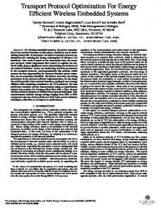
GP5:) (cm) dmRWF
GP5&I (cm) d_Cf
d_Ce GP5&H (cm)
8 6 4 2
0 N1 Fig. 2.
N2
N3
N4
N5
N6
Node to relay distances using LOWFA vs conventional techniques
50 simulations in Fig.2. The average total node to R distance F WF ˆ in Fig.1(c) & dW F in Fig.2) (R dW mR obtained using LR mR is the lowest (36.5 cm) compared to the conventional relay C Cf Cf e positions at LRf & LC R (refer dmR & dmR in Fig.2) with ≈ 41.64 cm. Thus, the relay position obtained using LOWFA algorithm effectively minimizes the total distance traveled by signal through the tissue by moving the relay closer to the nodes. The power conservation achieved in each node is presented in Table.I. P tλ given is calculated assuming the minimal required SNR to be 7. The node life is estimated assuming a battery rating of 240 mAh and 10% duty cycle. As expected, F the relay position at LW extends the lives of all the nodes R with a minimum of 25 days upto a maximum of 100 days. The battery life extension achieved is significantly higher than the conventional schemes and therefore becomes a critical component in GC-IBN topology optimization. Scenario.2 Heterogeneous Node Distribution Having established the effectiveness of LOWFA algorithm, we proceed with the algorithm evaluation considering heterogeneous nodes that are positioned in different tissues with non-uniform bandwidth requirements η. We follow the simulation set-up same as that of homogeneous scenario with six nodes and the relay F ˆ in Fig.1(d)). Initially, we assume (R positioned at LW R that node N 1 is implanted in muscle (refer Fig.1(d)) with T1 =M & z1 =0 and that the other nodes are on surface with Tm =S & zm =0, ∀m ∈ {2, .., 6}. We assume equal bandwidth requirement ηm =1, ∀m ∈ {1, .., 6} for all the nodes. From the resulting node to relay distance di-S mR , ∀i ∈ {S, M }, it is -S observed that the dM 1R obtained from N 1 to R is significantly lower than the dS-S mR , ∀m={2, .., 6} as depicted in Table.II. This ensures minimum P tλ for N 1, as desired for an implant in muscle. The corresponding battery life of N 1 is extended to 23.5 years that is atleast 1 year more than the rest of the nodes. On average, an improvement of 4% to 17% in battery life is TABLE I.
C OMPARISON OF P tmλ (μW) & NODE LIFE ( DAYS ) IN Cf Ce F 1 WITH RELAYS AT LW R , L R & LR
SCENARIO
F P tW λ Cf P tλ e P tC λ
N1 1.6 2.1 2.2
N2 .84 2.1 2.0
N3 .82 1.9 1.9
N4 1.7 2.0 2.9
N5 1.5 3.3 2.8
N6 1.9 2.9 3.5
LifeW F LifeCf LifeCe
8446 8407 8398
8514 8407 8415
8515 8426 8426
8440 8415 8346
8455 8305 8351
8422 8346 8293
2015 IEEE Wireless Communications and Networking Conference (WCNC): - Track 3: Mobile and Wireless Networks
1
10
12
η =1
Mean dmR
8
d (cm)
2R
d M−S
7
d (cm)
−2
10 10
S−S mR
Mean d
8
10
−3
S−S 1R
d 9
S−S
10
η1=3
−1
10
S−S
d1R
1
η1=2
0
10
6
6 5
−4
10
4
4
−5
10
3 2
−6
10
2
−7
10
Fig. 3.
0
2
4
α
6
8
10
0 1
2
3 η1
4
5
1 1.5
2 mean(η ,η ,η ,η ,η ) 2
3
4
5
2.5
6
(Left) d1R vs α for varying η; (Mid) d1R and mean dmR for varying η; (Right) Change in d1R with varying mean ηm
TABLE II. C OMPARISON OF MEAN di-S mR ( CM ), P tλm (μW) & NODE F LIFE ( YEARS ) AT LW R , T = [2111111], η = [111111] & α = 4
di-S mR
(WF) F P tW λ WF Life Improvement
N1
N2
N3
N4
N5
N6
0.4 0.1 23.5
9.1 14.9 20.44 13%
9.0 13.3 20.7 12%
8.5 10.6 21.3 9%
7.8 4.2 22.5 4%
9.3 21.1 19.4 17%
VI.
I NFLUENCE OF α IN di-S mR ; T = [211111] & η = [111111]
TABLE III.
α
N1
N2
N3
N4
N5
N6
2 4 10
3.4 0.4 1E-3
6.6 9.1 13.3
9.6 8.9 15.6
6.1 8.5 14.4
6.1 7.8 7.9
9.3 9.3 10.1
when the mean ηm , ∀m = {2, .., 6}, increases from 1 to 2, -S the minimized dM 1m value rises from 1.6 cm to 4.8 cm. This indicates that the priority given to a node for a high η declines with the rise in mean η of other nodes in cluster, achieving energy balance reasonably.
achieved for N 1 compared with all the other nodes. In the above analysis in Table.II, α is set as 4. Table.III M -S illustrates the influence of α on di-S mR . When α=2, the d1R is minimized by a factor ranging from 0.80 to 1.82 when compared with other nodes. When α is increased to 4, the average -S dM 1R obtained is 0.4 cm, which is reduced by ≈ 18.5 to 22.3 M -S times than dS-S mR , ∀m={2, .., 6}. For α=10, the average d1R is only 1e-3 which is closer to zero and this makes the decrease in -S dM 1R 7899 to 15600 times the other nodes. Thus, the distance dependent power consumption of implant can be controlled against the on-surface nodes by varying α. This effect is further emphasized with respect to changes in η in Fig.3(left). For the same T as above, when η1 is increased from 1, indicating same traffic requirements as other nodes, to 3 where N 1 has 3-fold F increase in traffic, the corresponding dW 1R obtained is further reduced to decrease energy consumption due to increase in traffic. Thus the proposed algorithm intends to bring the relay closer to the node with higher bandwidth requirement in order to avoid quick draining. With α being unchanged, the effect of varying η for nodes in the same tissue is analyzed in Fig.3(mid). Considering node N 1, when η1 is increased from 1 to 5, the average dS-S 1R reduces from 8 cm to 0.3 cm, albeit with an average increase in dS-S mR of other nodes by ≈ 1.5 cm. Thus P tλm is reduced for nodes with higher ηm and increased for nodes with lower ηm . The bandwidth requirement based relay positioning also helps in establishing energy balance among co-located nodes. Fig.3(right) illustrates the change in the optimized distance of the node N 1 with respect to the change in mean ηm , ∀m={2, .., 6} of other nodes in the same cluster. For η1 =5,
1730
C ONCLUSIONS
The proposed relay positioning strategy for GC-IBN using Weiszfeld algorithm demonstrates the potential of energy saving in embedded implants by bringing the relay closer to the IBN nodes. An effective increase in the life of implants is demonstrated for varying node demands by comparing the results of the proposed strategy with conventional relay positioning schemes in classical WSNs. The algorithm is adaptive to the variations in the tissue where the node is located, the individual bandwidth requirement and the average bandwidth requirement of all the nodes in cluster. The proposed relay positioning strategy will enable optimized topology design for the galvanic coupled intra-body communication. ACKNOWLEDGEMENTS This material is based on the work supported by the U.S. National Science Foundation Grants No. CNS-1136027 and CNS-1453384. R EFERENCES [1]
[2]
[3]
[4] [5] [6]
[7]
[8] [9]
M. Swaminathan, J. S. Pujol, G. Schirner and K. R Chowdhury, “Multipath 2-Port Channel Characterization for Galvanic Coupled Intra-body Communication,” Conference on Body Area Networks, Sept. 2014. M. S. Wegmueller et al.,“Signal transmission by galvanic coupling through the human body,” IEEE Transactions on Instrumentation and Measurement, vol. 59, pp. 963–969, 2010. R. Ramanathan and R. Rosales-Hain, “Topology control of multihop wireless networks using transmit power adjustment,” in IEEE INFOCOM, vol. 2, 2000, pp. 404–413. D. Avidor et al, “Transmit power distribution of wireless ad hoc networks with topology control,” in IEEE INFOCOM, 2007, pp. 46–52. J. Pan et al., “Optimal base-station locations in two-tiered wireless sensor networks,” IEEE Trans on Mobile Computing, vol. 4, pp. 458–473, 2005. Y. Wang, X. Fu, and L. Huang, “A storage node placement algorithm in wireless sensor networks,” in IEEE conference on Frontier of Computer Science and Technology,, 2009, pp. 267–271. P. Vecchia et al.,“Exposure to high frequency electromagnetic fields, biological effects and health consequences (100 kHz-300 GHz),” International Commission on Non-Ionizing Radiation Protection, 2009. T. S. Rappaport, Wireless Communications Principles and Applications, 2nd ed. Prentice Hall, 2001. M. R. Korupolu, C. G. Plaxton, and R. Rajaraman, “Analysis of a local search heuristic for facility location problems,” Journal of algorithms, vol. 37, no. 1, pp. 146–188, 2000.