Advanced Research School for Technology and Product Simulation, CIPET, ... Abstract: Optimization of cycle time in injection molding plays a vital role in ...
Middle-East Journal of Scientific Research 13 (7): 944-946, 2013 ISSN 1990-9233 © IDOSI Publications, 2013 DOI: 10.5829/idosi.mejsr.2013.13.7.2934
Optimization of Injection Molding Cycle Time Using Moldflow Analysis M. Vishnuvarthanan, Rajesh Panda and S. Ilangovan Advanced Research School for Technology and Product Simulation, CIPET, Chennai, India Abstract: Optimization of cycle time in injection molding plays a vital role in manufacturing of plastic parts to improve the productivity of the process. At the same time it should not affect the quality of the final product. This paper describes the cycle time optimization of Hinge Locator – Guided support plastic part, through a repeated number of analyses which was carried out by Moldflow simulation software. The process parameters like cooling time, Injection time are optimized in which it contributes more in the cycle time. Experimental verification has been done with new optimized parameters in Injection molding machine. The results of the experiment showed a way to achieve the purpose of optimizing the injection molding machine in a sensible and cost efficient way. Key words: Injection molding
Moldflow
Optimization
INTRODUCTION
Cooling time
Injection time
The Orthogonal Experiment: The orthogonal experiment design is a scientific testing method used in many factors experiment, it select part of representative points with even and ordering characteristics from the comprehensive test to do experiment by using probability, mathematical statistics and orthogonal principle and then use orthogonal table to reasonably arrange the experiments [2]. These experiments can scientifically and reasonably arrange the experiments, reduce the testing numbers, shorten the testing cycle and increase economic benefits. Through orthogonal experiment, the main influencing factors and optimizing parameters combination can be obtained by analysis the effects degree of different molding process parameters [3].
Thermoplastic injection molding is a well known process for manufacturing effortless and complex shaped products in short time and at low cost. Nowadays there is a need for optimizing the processing parameters to increase productivity. In the cycle time the cooling time can represent more than 70% of the injection cycle. Cutting down the cycle time for each part is a major concern in injection molding machine. In order to set the processing parameters, they commonly follow on experience and trial-and–error method. This process becomes inadequate and unpractical for complex products. As a consequence the designers need a more powerful tool to analyze and to optimize the process. This project is to design an experiment to optimize an injection molding machine by manipulating parameters to reduce cycle time. However the development of CAE technology especially the Moldflow software, the number of testing mold can be reduce and the efficient can be improved by using CAE software to analyze, evaluate and optimize the related process data [1]. In this work, the combined effects of multi molding process parameters are analyzed by the combination of orthogonal experiments and moldflow simulation tests and then the sensible gate location and optimized parameter combination is obtained.
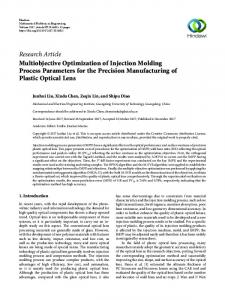
Creating Finite Element Model: In this work, the Hinge locator as a guiding support for handicapped people was take up as an example to express the whole optimizing process. The modeling is done by one of the modeling software unigraphics NX6. It is then imported to Moldflow by IGES format. The modeling and meshed product in Moldflow is shown in the Figures 1 and 2. The plastic material used for the product is LG chem. (Korea) ABS. The thickness of the product is 2mm. The dimensions are 60mm x 42mm x 32mm. There are three mesh types in Moldflow software including
Corresponding Author: M. Vishnuvarthanan, Advanced Research School for Technology and Product Simulation, CIPET- Chennai, India. Tel: +91- 9943769268.
944
Middle-East J. Sci. Res., 13 (7): 944-946, 2013 Table 1: Suitable gate location Gate Location 1. 2. 3. 4. 5. 6. 7. 8.
Fig. 1: Modeling Product
Fill Time
Shear Rate
Shear stress
Warpage (all)
0.7552 0.7590 0.8629 0.7520 0.7572 0.7533 0.7589 0.7595
8007.4 5260.6 4028.0 4008.0 6751.1 4631.2 5264.6 6224.7
3.813 5.75 4.83 2.75 5.57 6.57 5.78 5.98
0.2466 0.2630 0.2286 0.2233 0.2334 0.2687 0.2633 0.2590
Table 2: Process parameter range Melt Temperature (°C)
Mold Temperature (°C)
Injection Time (s)
Cycle Time (s)
220 -260
40 – 80
1.5 -3
24 - 35
Table 3: Existing Values
Fig. 2: Meshed Model Midplane, 3D and Fusion. Due to the thickness of the plastic product, we adopt the surface meshes (Fusion) and used grid mesh tool to modify mesh defects [4].
Mold close Time (s)
Injection Time (s)
Packing Time (s)
Cooling Time (s)
cycle time (s)
5
1.5
6.5
22
35
Table 4: Orthogonal Experiments
Injection Molding Process Analysis Suitable Gate Location Analysis: The Best gate location result is generated by the Gate Location analysis. This result rates each place on the model for its suitability as an injection location. The most suitable areas are rated as best and are colored blue. The least suitable areas of the model are rated as worst and colored red. A best location rating does not necessarily mean that the part can be filled from this location. This must be checked by running a full analysis. Designers can quickly and accurately work out the best gate location by Moldflow software, thereby improving the efficiency of the mold design, the quality of products and reducing the cost [4]. Various gate location analyses have been carried out to get the best gate location which is shown in the Table 1. In this the fill time, shear rate, shear stress, warpage analyses were done. The best option is the minimum of all the values. The suitable gate location is the 4 th option.
Melt Temperature (°C)
Mold Temperature (°C)
Injection Time (s)
Cycle Time (s)
Product Quality
240 240 240 240 240 240 240 240 240 240 240 240 240
60 60 60 60 60 60 60 60 60 60 60 60 60
1.5 1.5 1.5 1.5 1.5 1.5 1.5 1.5 1.5 1.5 1.5 1.5 1.5
35 34 33 32 31 30 29 28 27 26 25 24 23
Good Good Good Good Good Good Good Good Good Good Good Good Bad
Table 5: optimized parameters Melt Temperature (°C)
Mold Temperature (°C)
Injection Time (s)
Cycle Time (s)
240
60
1.5
24
Orthogonal Experiment Design: According to the experience and simulation analysis, the melt temperature, mold temperature, injection time and cooling time are considered as the main factors to optimize cycle time. The total cycle time is the sum of Mold close time, Injection Time, packing time and cooling time [4]. The existing values are shown in Table 3. Here the Melt temperature, Mold temperature, Injection time, Packing time as constant and the cooling time is varied. In this the orthogonal test method is adopt, so the orthogonal table is used to arrange the experiences and the simulation result is shown in Table 4.
The Scope of Orthogonal Process Parameters: In this work, the cycle time Index is considered as the main factor to evaluate the surface quality of the product. In the cycle time, the cooling time and Injection time is the most important parameters. Any change in these parameters, will affect the surface quality. The range of variables is very important in the process parameter optimization design. According to the reference value of Moldflow software and practical experience, the range of variables are adopt in this work are shown in Table 2. 945
Middle-East J. Sci. Res., 13 (7): 944-946, 2013
Analyze the Effects Degree of Different Molding Process Parameters for Cycle Time: The data of the effects degree of different molding process parameters for cycle time is shown in Table 4. To identify the effects degree of different molding process parameters for cycle time, the range is used to analyze the results of orthogonal experiment. From the data in Table 4, it is obvious that the sequence of effects degree ranked in melt temperature, mold temperature, injection time, packing time and cooling time.
REFERENCES 1.
2.
3.
Test Optimization Results: The result of cycle time optimization using the parameter combination in Table 4 to simulate by Moldflow software is 24 secs. The final optimized parameters which are shown in the Table 5.
4.
CONCLUSION In this study, the simulation for optimization of plastic injection molding processing parameters based on the optimization of cycle time have been performed by Moldflow software. In finding optimum values, the use of Moldflow, Orthogonal process is exploited. Mold temperature, melt temperature, packing time and cooling time are the important process parameters. When using the process parameter recommended by Moldflow the cycle time reduced from 35 secs to 24 secs. All other parameters are under the limit only. By using this parameters given by Moldflow, it has been verified in Injection molding machine and the obtained final quality of the product gave the good results. Thus the Moldflow software is a Preventive and Corrective tool, helps the engineers to analyze the process, to decrease the cycle time and to improve the quality of the product.
946
Liu, J., 2005. Application of Moldflow Technology in buckling analysis of plastic part, Mould Industry, 33: 32-34. Sun, L., D. Zhang and X.M. Liu, 2009. Optimization of molding processing parameters for automobile bumpers based on minimization of sink index, China Plastics, 23: 55-60. Zhao Longzhi. Chen Binghui and Li Jianyun, XXXX. Optimization of Plastics Injection molding processing parameters based on the minimization of sink marks. Plastics Insight, XXXX. Moldflow Corporation, 91 Hartwell Avenue, Lexington, MA, 02421.