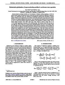
Development of New Optimization Capabilities in the Blow Moulding Process Francis Thibault and Denis Laroche 26th SIGBLOW Meeting April 3, 2001
Outline
Development of an Optimization Manager Automation of BlowOp Software Rapid Estimation of the Extrusion Flowrate
Optimization of the Mechanical Performance Brief Overview of the Taiwan Project 2
Optimization Manager
Objectives: Eliminate the manual file manipulations during
optimization process
Decrease the part development time Allow designers to put more effort to analyze results 3
Optimization Manager Scheme 2 output files
Parmesh Programming points vs iteration
Interface
BlowSim BlowLoop Program
Flash BlowOp
# iteration defined by the user
Flow rate, minimum thickness, maximum thickness, thickness st. dev., % flash, weight of part, ... vs iteration
Results Send to you an email when optimization loop starts, ends up and while errors are detected during the optimization process (UNIX)
4
Case study: Optimisation of Operating Conditions for a Bottle Part
mould1.pat
Extrusion time : 30 sec Initial flowrate : 5.411 cm3/s Number of programming points : 6 Initial % die opening : 75% Parison length : 320 mm Targeted part thickness : 2 mm
Calculated using BlowLoop
mould2.pat
HDPE Material
part.pat
5
Definition Files for BlowLoop
[thibault@octane3]:test> dir Feb 7 21:05 bottle.blowop.def Feb 7 21:05 bottle.blowsim.def Feb 7 21:05 bottle.flash.def Feb 8 08:12 bottle.opt.def Feb 7 21:05 bottle.par.def Feb 7 21:05 bottle.results.def Oct 27 13:54 mould1.pat Oct 27 13:54 mould2.pat Oct 27 13:54 part.pat
bottle.opt.def is the BlowLoop definition file 6
BlowLoop Definition File ============================ OPTIMIZATION LOOP PARAMETERS ============================ General parameters -----------------Language (English=2) .................................. 2 Use email to inform user during optmization process ... 1 Email definition ......................................
[email protected]
Programs and definition filenames involved in the loop -----------------------------------------------------PARMESH ............................................... BLOWSIM ............................................... FLASH ................................................. BLOWWARP .............................................. BLOWSTR ............................................... BLOWOP ................................................ RESULTS ...............................................
1 1 1 0 0 1 1
Problem type -----------Thickness distribution optimization ................... Estimation of flowrate for a given parison length ..... Thickness distribution for performance specifications .
1 0 0
Thickness distribution optimization ----------------------------------Maximum number of iterations .......................... 5 Tolerance (average, std dev. thickness) ............... 0.010E+00 User-defined gain for parison thickness update ........ 0.500E+00
7
Screen Output of the BlowLoop program Blowloop> =================================================== Blowloop> OPTIMIZATION OF PARISON/PART THICKNESS DISTRIBUTION Blowloop> =================================================== Blowloop> Iteration Number :
1
Blowloop> Executing PARMESH ... --> Normal end of PARMESH program ... Blowloop> --> Times and Parison Positions have been modified in bottle.blowsim.def according to results of PARMESH program !! Blowloop> Executing BLOWSIM ... --> Normal end of BLOWSIM program ... Blowloop> Executing FLASH ... --> Normal end of FLASH program ... Blowloop> Executing BLOWOP ... --> User-defined gain : 0.50 --> Normal end of BLOWOP program ... Blowloop> Executing RESULTS ... --> Normal end of RESULTS program ...
Blowloop> Relative errors with the previous iteration: Thickness distribution -------------------------Average StdDev 100.00% 100.00% ( 2.289)mm ( 1.049)mm
8
Architecture of Test Directory [thibault@octane3]:test> dir Nov 7 21:05 bottle.blowop.def Nov 7 21:05 bottle.blowsim.def Nov 7 21:05 bottle.flash.def Nov 8 08:12 bottle.opt.def Nov 7 21:05 bottle.par.def Nov 7 21:05 bottle.results.def Nov 7 19:42 iter01/ Nov 7 19:49 iter02/ Nov 7 20:57 iter03/ Nov 7 21:04 iter04/ Nov 7 21:12 iter05/ Oct 27 13:54 mould1.pat Oct 27 13:54 mould2.pat Oct 27 13:54 part.pat Nov 7 21:05 prog_points.txt Nov 8 07:45 report.txt Iter0(1-5) prog_points.txt report.txt
Directories for each optimization case 2 Output files
9
Output file #1 : prog_points.txt ---------------------------| # iter. time %open | ---------------------------| | | 1 0.000 75.000 | | 5.000 75.000 | | 10.000 75.000 | | 15.000 75.000 | | 20.000 75.000 | | 25.000 75.000 | | 30.000 75.000 | | | | 2 0.000 29.690 | | 4.810 58.710 | | 10.830 88.270 | | 16.990 92.150 | | 22.340 71.800 | | 26.320 38.080 | | 30.000 30.870 | | |
| 3 0.000 20.210 | | 5.740 76.010 | | 11.880 85.210 | | 17.660 77.030 | | 23.110 68.960 | | 26.740 25.950 | | 30.000 17.180 | | | | 4 0.000 10.910 | | 5.850 75.850 | | 11.870 79.390 | | 18.060 83.700 | | 23.770 72.440 | | 27.090 16.810 | | 30.000 7.540 | | | | 5 0.000 7.960 | | 6.250 82.900 | | 12.240 76.520 | | 18.320 78.760 | | 24.100 72.000 | | 27.150 9.540 | | 30.000 5.000 | | | ----------------------------
10
Output file #2 : report.txt -----------------------------------------------| User-defined gain for BLOWOP module : 0.50 | ----------------------------------------------------------------------------------------------------------------------------------------------| ------------ Thickness --------------- Part ----- | | # iter. Flowrate Par. Length Average Minimum Maximum Std_Dev. Flash Volume Weight | | (cm^3/s) (mm) (mm) (mm) (mm) (mm) (%) (cm^3) (kg) | -----------------------------------------------------------------------------------------------| 1 5.411 321.452 2.289 1.431 6.344 1.049 5.15 130.75 0.09545 | | 2 4.943 320.467 2.115 0.838 4.731 0.911 4.90 128.56 0.09385 | | 3 4.746 319.438 1.935 1.314 5.190 0.585 4.83 125.84 0.09186 | | 4 4.649 318.885 1.949 0.848 4.470 0.577 5.27 125.23 0.09142 | | 5 4.575 319.280 1.945 1.383 4.851 0.414 4.83 123.48 0.09014 | -----------------------------------------------------------------------------------------------------------------------------------| # iter. Node Element CPU Time | | (min) | ------------------------------------| 1 944 1856 7.2 | | 2 944 1856 7.7 | | 3 928 1824 7.0 | | 4 928 1824 7.0 | | 5 928 1824 7.5 | -------------------------------------
11
Optimization Results Targeted thickness (set-point) = 2 mm
Thickness (mm) 7.0
0.5
Iteration #
1
2
3
4
5 12
Rapid Estimation of the Extrusion Flowrate Question: What is the extrusion flowrate that will give a desired parison length by taking into account the sag effect ? Die Mould
Extrusion flowrate = ?
L = 320 mm
13
Algorithm used for the Extrusion Flowrate Determination Parison length Linear inter. or extrapolation
Quadratic inter. or extrapolation
Target parison length (F4quad., L4BlowSim) (F3linear, L3BlowSim) (F2, L2BlowSim) (F1, L1BlowSim)
Flowrate 14
Case Study with the Blow Moulded Bottle Extrusion time : 30 sec %die opening : 75% (constant) -----------------------------------------| Parison length targeted : 320.000 mm | ------------------------------------------------------------------------------------------------------------------| ------------ Thickness -----------| | # iter. Flowrate Par. Length Average Minimum Maximum Std_Dev. | | (cm^3/s) (mm) (mm) (mm) (mm) (mm) | -------------------------------------------------------------------------| 1 4.000 232.168 6.464 6.338 6.749 0.115 | | 2 4.444 259.818 6.435 6.293 6.749 0.127 | | 3 5.411 321.395 6.369 6.214 6.749 0.150 | -------------------------------------------------------------------------------------------------------------| # iter. Node Element CPU Time | | (min) | ------------------------------------| 1 704 1376 1.8 | | 2 768 1504 2.9 | | 3 944 1856 3.7 | -------------------------------------
is increasing with the parison length
sag effect is becoming more significant
15
Optimization of the Mechanical Performance To satisfy the mechanical performance of the final part such as Bottle topload Bottle pressure resistance Maximum part deflection for a given force, pressure or vacuum
Part thickness distribution has to be evaluated to satisfy these requirements
16
Problem Formulation Design Objective Function:
min Part Weight T () dS
Subjected to constraints: () < max
Design variables
Tmin < T() < Tmax Updating the nodal part thickness: Ti
q 1
Ti q
( iq max )
max
Ti q 17
Case Study: Two Types of Loading
Hooke’s Law:
E E = 879 MPa (HDPE)
P
Initial thickness = 2 mm Yield tensile strength = max= 33 MPa Bottle under Pressure (7.5 atm, 110 psi)
Topload (Displ. 5 mm, 5 sec)
18
Structural Analysis using BlowSim: Optimization Results Pressure Case Thickness
Thickness
Stress
mm
Stress
MPa
mm
MPa
2
40
4.16
32
0
0
1
0
Initial Design (Weight = 119 g)
Optimized Design (Weight = 75 g)
19
Structural Analysis using BlowSim: Optimization Results Topload Case Thickness
Thickness
Stress
mm
Stress
MPa
mm
MPa
2
47
3.98
33
0
0
1
0
Initial Design (Weight = 119 g)
Optimized Design (Weight = 74 g)
20
Optimization Results: Final Thickness Distribution Final Thickness Distribution
Topload Case
Pressure Case
mm
mm
mm
4.16
3.98
4.16
+
75 g 7
=
74 g
1
To satisfy both loadings
1
82 g
1
Ti Final Max (Ti Pressure, TiTopload )
21
Joint International IMI-IMTI-Taiwan Project Global market competition is forcing manufacturers to drastically reduce time-to-market for new parts
Reduced part development time & cost
MDO tool for blow molded automotive parts Improved part quality 22
Objectives of the Project Develop an innovative MDO software environment for the design of blow molded automotive interior parts
MDO will integrate process simulation tools, performance simulation tools and optimization techniques
MDO Software will be available to all SIGBLOW members 23
Canadian Industrial Participant Lear Corporation Inc. (Concord, Ontario) manufacturer of blow molded automotive interior parts
Seat Backs
Air Ducts
Windshield Washer Reservoirs Cooling Liquid Reservoirs Complex Planar-carpet Part 24
MDO Software Environment Tasks : • Validation of the simulation technology on very complex part • Find a new optimization strategy to get uniform or non-uniform thickness distribution of the final part (soft computing techniques) • Validate the warpage prediction on complex part • Develop an optimization strategy for minimizing warpage (gradient & soft computing techniques) • Development of a software environment integrating process, performance simulation and optimization tools 25
Soft Computing (Taiwan) Initial Design
Orthogonal Array (Taguchi Method)
BlowSim Simulation
Parameter Optimization
Neural Network
Search
Verification Simulation
Genetic Algorithm
Refine
No
YES
Direct Model Programing Point & Die Open
f(x)
f(x)
f(x)
f(x)
f(x)
f(x)
f(x)
f(x)
...... Input Layer
Wall Thickness
End
......
Neural Networks
Satisfactory
f(x)
hidden Layer
Output Layer
26
Soft Computing (Taiwan) Design Objective function: min
Ti Tt f n j
1
2
Ti: part thickness Tt: target part thickness
Fuzzy Logic Optimization Algorithm :
Pi 1 t j Pi t j S j Rule 1: If thickness Ti is PB then Rule 2: If thickness Ti is PS then Rule 3: If thickness Ti is ZE then Rule 4: If thickness Ti is NS then Rule 5: If thickness Ti is NB then
Sj is NB Sj is NS Sj is ZE Sj is PS Sj is PB
P: %die opening
PB (Positive Big) PS (Positive Small) ZE (Zero) NS (Negative Small) NB (Negative Big) 27
Preliminary Results from Fuzzy Logic Algorithm Target part thickness = 2 mm
28
Software Integration on the Web (IMTI) Minimisation of warpage
Optimisation of Mechanical Performance Database
Load 1
Load 2
Load 3
Case 1
Case 2
Case 3
Application Servers Web Server
Internet Web Server
Web Browser
Web Browser
BlowLoop
Database BlowView
29
Preliminary Results of Software Integration
30
Conclusion Optimization Manager has been developed
Rapid Estimation of the Extrusion Flowrate Decrease part development time Better simulation predictions (avoid manipulation errors) Preliminary Results of Mechanical Performance Preliminary Results from joint IMI-IMTI-Taiwan Project Development of New Optimization Capabilities: Minimize the warpage phenomenon (EBM) Optimize the parting line position (EBM) Optimize the operating conditions (ISBM)
31
Optimization of Mechanical Performance: Case Study Initial thickness = 10 mm
Hooke’s Law: E = 879 MPa
F = 450 N
E
---------------------------------------------------| ------> Minimize the Weight of the Part thickness of the part | ----------------------------------------------------
32
Optimization of Mechanical Performance: Structural Analysis Results using BlowSim Iteration No.
Thickness Profile
(T , )
mm
Stress Profile
( vm , ) MPa
1
(10,0)
(4.97,0.25)
2
(4.97,0.21)
(10.02,0.25)
3
(4.98,0.28)
(9.996,0.19)
13
(4.99,0.39)
(9.998,0.15)
33