Proceedings of the 2006 IEEE Conference on Computer Aided Control Systems Design Munich, Germany, October 4-6, 2006
ThB02.2
Optimization of Signal Processing Software for Control System Implementation Shuvra S. Bhattacharyya and William S. Levine Abstract— Signal processing plays a fundamental role in the design of control systems — the portion of a digitallyimplemented control system between the sensor outputs and the actuator inputs is precisely a digital signal processor (DSP). Consequently, effective techniques for design and optimization of signal processing software are important in achieving efficient controller implementations. Motivated by these relationships, this paper reviews techniques for modeling signal processing functionality in a manner that exposes aspects of application structure that are useful for mapping the functionality into efficient implementations. The paper then introduces some representative techniques that operate on such models to systematically derive optimized implementations from them.
I. INTRODUCTION Today almost all controllers are implemented digitally. In many complex or geographically distributed systems the controller operates over an automated communication network. Such embedded networked control systems present new challenges to the control system designer. This paper addresses the interaction between two of these challenges. As in any control system it is essential to have the controller operate in real time. Each input must be there at the instant it is needed. Delayed or missing data can cause disasters. Hence, the timing of the computations must be precisely specifiable. Several issues operate to make the timing question hard. Delays due to communication problems are relatively well understood and techniques for preventing them developed [1], [2], [3], [4]. However, there is also the possibility of delays due to the software. The likelihood of such delays tends to increase as the complexity of the control algorithms increases. Because computing hardware is so cheap and inexpensive sensors are becoming more and more available, there is increasing pressure on the control system designer to incorporate more and more sophisticated functions into the controller. In addition, the control computer is likely to be time shared among many different control loops. The portion of a digitally-implemented control system between the sensor outputs and the actuator inputs is a digital signal processor (DSP). This is well known [5]. This means that techniques developed for optimizing DSP software apply equally well to controller software. However, the objectives and criteria are different. Specifically, in many signal processing applications S. S. Bhattacharyya is with the Department of Electrical and Computer Engineering, and Institute for Advanced Computer Studies, University of Maryland, College Park, MD, 20742, USA,
[email protected]. W. S. Levine is with the Department of Electrical and Computer Engineering, and Institute for Systems Research, University of Maryland, College Park, MD, 20742, USA,
[email protected].
0-7803-9797-5/06/$20.00 ©2006 IEEE
the main issue is minimizing the power needed. In most control applications the power used for signal processing is negligible compared to that used for control. The automobile is a good example. Various researchers have studied the problem of realtime, software implementation of controllers, where a single processor must be time-shared across multiple controllers in such a way that all controllers reliably keep up with their respective sampling periods. Caspi and Maler present a recent overview of such techniques in [6]. The developments in this paper are largely complementary to the existing body of work on real-time controller implementation. When each controller is viewed as a signal processing system, and attacked by state-of-the-art techniques for optimizing signal processing software, the task of real-time coordination becomes easier because the individual controllers consume less resources, (e.g., their worst-case execution times are significantly improved). This enables more functionality to be mapped to a given processing platform, or allows a cheaper platform — with slower processors — to be employed for a given set of functionality. The advantages of applying a signal processing design flow are especially useful when complex controllers, such as multirate controllers, are involved. II. MODELING OF SIGNAL PROCESSING SOFTWARE Signal processing system design is increasingly carried out through block diagram based environments. Block diagram representations are a natural match for the signal flow graph descriptions that are used by algorithm designers. In the context of efficient implementation, block diagram representations of signal processing algorithms are attractive because they can be associated with coarse-grain dataflow semantics that expose opportunities for hardware and software optimization. Dataflow is a model of computation in which applications are represented as directed graphs whose vertices correspond to computations and whose edges specify logical channels through which the output values of computations become the input values for subsequent computations. Dataflow programming is related to the actor model of concurrent computation [7], and vertices in a dataflow graph are often referred to as actors of the graph. A dataflow actor can execute whenever it has sufficient data on its input edges to perform meaningful computation. Upon execution, the required input data values are consumed from the input edges
1562
and the resulting output data values are produced onto one or more output edges. Unlike sequential programming languages, where execution of operations follows the ordering of statements in the program, a dataflow representation specifies nothing about the ordering of operations apart from the precedence constraints that are implied by the flow requirements of the edges (the source actor of an edge must execute before the sink actor is allowed to consume the data that is produced by the source). Dataflow actors can have arbitrary complexity. In the design of signal processing systems, examples of practical actors range from simple computations, such as addition and multiplication, to signal processing blocks, such as FIR or IIR filters, and even complete subsystems, such as audio and video coders. For optimization of signal processing software, the intermediate level of complexity in this range is most useful — the most effective optimization can be carried out if much of the functionality is expressed in terms of medium-scale functional blocks, and this is also the level of abstraction at which dataflow programming is most natural to use as well. When dataflow is used to implement embedded hardware or software, the internal functionality of a dataflow actor is specified in a programming language that is suitable for translation using the tools associated with the target platform. For example, C or assembly code are commonly used when the target is a microcontroller or programmable digital signal processor, and Verilog or VHDL is used when the target is a field programmable gate array or ASIC subsystem. Given a dataflow edge e, we denote the source and sink actors of e by src(e) and snk (e), respectively. A dataflow edge also has a non-negative integer delay dly(e) associated with it. Logically, each unit of delay is equivalent to the z −1 operator in signal processing theory. In the implementation of control systems, delays can be useful in the organization of state variables that persist from one execution of the graph to the next. In practice, a dataflow edge e is implemented as a block of storage elements. This block is called a buffer for the edge. The number of storage elements provided in the buffer must not be exceeded at any time by the number of live data values on the edge, where a data value is considered live if it has been produced by src(e) or placed on e by initialization, and it has not yet been consumed by snk (e). Delays on e are often implemented by initializing the buffer to contain dly(e) live data values. Because dataflow specifications do not over-specify execution ordering, they provide more freedom to designers and tools in deriving execution orderings (schedules) or ordering policies (schedulers) to implement the dataflow graph in hardware or software. This is a large benefit because the execution ordering has a major impact on relevant implementation metrics, including code size, data memory requirements, latency, throughput, and power consumption [8]. Specialized forms of dataflow that have been developed for signal processing are also useful because they expose various
other forms of application structure that facilitate powerful verification and optimization techniques. When a dataflow graph is used to represent a signal processing application, a source actor in the graph (an actor that does not have any input edges incident to it) can be used to represent input to the application that arrives asynchronously with respect to execution of the graph. Actors that depend, directly or indirectly, on data arriving from such source actors are then naturally triggered by the physical devices that correspond to the source actors. Since the number of samples that will be injected through a source actor is often not known (or even bounded) in advance, dataflow graphs are usually assumed to execute infinitely. For example, in a software implementation of a dataflow graph, the code for the graph is typically encapsulated within an infinite loop. Note that this does not imply continuous execution of the dataflow graph, since the infinite loop may be suspended from time to time when it is waiting for external input to arrive (e.g., from a sensor). Under such infinite execution, two problems that are especially important when implementing a dataflow graph are ensuring bounded memory requirements for the edges in the dataflow graph, and ensuring deadlock-free operation for the graph as a whole. If these are not ensured, then no matter how much the hardware and software are optimized, the final implementation may halt prematurely or exhaust the resources of the processing platform, a potentially disastrous problem in a controller. Deadlock in a dataflow graph arises when a cycle is present such that for each edge e in the cycle, there is insufficient data on e for the sink actor of e to execute. Here, by a graph cycle, we mean a finite sequence of edges e1 , e2 , . . . , en , such that a) src(e1 ) = snk (en ), and b) for i = 1, 2, . . . , (n − 1), snk (ei ) = src(ei+1 ). Deadlock is the result of a defective dataflow graph specification, and may occur before or during execution. In the former case, analysis tools can sometimes detect the deadlock and report the defect to the programmer. In the context of infinite execution, as motivated above, deadlock is usually problematic because it results in the premature termination of part or all of the dataflow graph. III. DECIDABLE DATAFLOW MODELS The dataflow process network model [9], which is a special case of the Kahn process network model [10], is a general form of the dataflow model of computation that is suitable for design and implementation of signal processing systems. A key advantage of dataflow process networks is their support for efficient scheduling and context-switching across actor executions. Dataflow process networks provide a Turing complete model, so there is no loss of expressive power when programming in this model. However, for signal processing applications, specialized models that are significantly restricted forms of dataflow process networks are more popular compared to dataflow process networks in their general form.
1563
Among these, the decidable dataflow models are especially useful. A decidable dataflow model is a dataflow model of computation such that bounded memory requirements and deadlock-free operation can be determined statically (before execution of the system), in finite time. Furthermore, automated techniques are available to determine whether or not an application expressed in terms of a decidable dataflow model requires bounded memory and will run without deadlock regardless of the input signals that are applied. Such “decidability” comes at the expense of limited expressive power: given any decidable dataflow model, there are some applications that cannot be expressed in terms of the model. This limitation can be a major problem in generalpurpose computation and many application domains. However, in signal processing, important classes of applications conform naturally to the restrictions of decidable dataflow models. In addition to providing for detection of unbounded memory requirements and deadlock, the restrictions imposed by decidable dataflow models facilitate powerful techniques for optimizing hardware and software implementations. In the context of control system implementation, such optimization techniques are especially important given the complex range of design constraints that must be satisfied. Two specific forms of decidable dataflow that are popular in commercial dataflow-oriented design tools are synchronous dataflow [11] and cyclo-static dataflow [12]. We focus in this paper on the former since its methods are more mature and are more widely used in currently-available tools for the design of signal processing systems.
X F1
M F2
G2
G1
G4
D
A1 F3
D
G3 G5
A2
Y
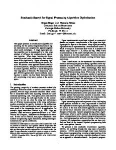
IV. SYNCHRONOUS DATAFLOW The synchronous dataflow (SDF) model of computation [11] is a restricted form of dataflow that has evolved into a de facto common denominator across most commercial dataflow-based design environments for signal processing. The key requirement of an SDF representation is that for each dataflow edge e, the number of data values produced onto e by src(e) throughout each execution of src(e) is a statically-known constant, and the number of data values consumed from e by each execution of snk (e) is similarly constant. These constant numbers of data values are denoted, respectively, by prd (e) and cns(e). For example, consider the academic PID controller described by the following equations [6]. S−1 = X−1 = 0.0
(1)
Sn = Sn−1 + 0.1 · In
(2)
Yn = 5.8 · +4 · Sn + 3.8 · 10.0(Xn − Xn−1 )
(3)
Figure 1 shows this controller represented as a synchronous dataflow graph. The SDF graph is derived by a direct translation of the equations into dataflow where constant multiplications are mapped to gain actors and sums are mapped to addition actors. Actor X in Figure 1 represents the input source. This actor injects one data value onto its
Fig. 1.
An SDF representation of an academic PID controller.
output edge every time it is executed. Actors G1 through G5 correspond to gains with factors 0.1, 3.8, 10.0, 5.8, and 4, respectively. Actors A1 and A2 represent adders, and actor M represents a subtracter. Actor Y represents the sink of the graph, which is executed once for each output result generated by the controller. The edges (F2 , M ) and (F3 , A1 ) are annotated with the letter “D” to indicate that they each have one unit of delay. Technically, for this to be a pure dataflow representation, the three heavy black dots, which represent replication of data from a single input onto multiple outputs, must also be represented as actors. Each of these can be modeled as an SDF actor that consumes, on each execution, a single data value from its input edge and outputs a single copy of that value on each output edge. These actors, sometimes called “fork” actors in dataflow terminology, are labeled as F1 , F2 , and F3 in Figure 1. A fork actor is usually “optimized away” when a software implementation is derived: the copying of data can easily be avoided by having the consuming actors read from a common
1564
buffer that corresponds to the input of the fork. Based on the initial conditions specified in (1), one unit of delay must be placed on each of the two edges (F2 , M ) and (F3 , A1 ), and when the graph is implemented, each delay is mapped into a single zero-valued unit of data that is placed into the corresponding buffer before the graph begins execution. The SDF graph of Figure 1 is a restricted form of SDF graph called homogeneous SDF. In homogeneous SDF, prd(e) and cns(e) are identically equal to one for all edges in the graph. This example is also particularly simple in the sense that the computational actors correspond to elementary scalar operations (additions, constant multiplications, and forks). As implied in Section II, dataflow is more commonly used to describe interactions between somewhat more complex functional modules. Therefore, in practice, the PID controller of (1-3) would more commonly be implemented as a single dataflow actor. Often a need arises for non-homogeneous SDF functionality, particularly when multirate signal processing is required. For example, consider a standard upsampler that increases the sample rate on its output by a factor of u. This can be implemented as an SDF actor that consumes one input value per execution, and produces u output values, which consist of the input value consumed together with u−1 zeros. Similarly, downsampling by a factor of d can be implemented as an SDF actor that consumes d values and produces 1 value per execution. As a third common example, a multirate FIR filter with a fractional sampling rate increase of u/d can be implemented as an SDF actor that consumes d values and produces u values on each execution. V. PERIODIC SCHEDULES One major advantage of SDF graphs is that they can be scheduled statically. Thus, one need not be burdened with the performance overhead and reduced predictability of dynamic scheduling mechanisms to coordinate the execution of an SDF graph. Bounded memory determination, deadlock detection, and efficient software implementation of SDF graphs can all be carried out through principles of static scheduling. Static scheduling of an SDF graph is performed by constructing a periodic schedule, which is a sequence of actor executions that satisfies certain properties, and then encapsulating the periodic schedule within an infinite loop to achieve the desired application of the graph to its unbounded input. Here, by a schedule we simply mean a sequence a1 , a2 , . . . of actor executions, where each ai represents an actor in the given SDF graph. As a schedule is executed, the numbers of live data values that are buffered on the edges changes as actors produce data onto their output edges, and consume data from their input edges. At any given point before, during, or after execution of a schedule, we refer to the state σ(e) of an SDF edge e as the number of data values buffered on e at that time. The state Σ(G) of the enclosing SDF graph G is then the collection of the states of the individual edges, which can
be expressed as Σ(G) = (σ(e1 ), σ(e2 ), . . . , σ(em )), where e1 , e2 , . . . , em is an ordering of the edges in the graph. A schedule is valid if throughout execution of the schedule, sufficient data is available for each actor execution. That is, for each input edge e of an actor, the state of the edge must satisfy σ(e) >= cns(e) prior to every execution of the actor. Intuitively, validity ensures that the schedule respects the production/consumption relationships that are specified in the dataflow graph. For example, consider the following two schedules for the PID controller: S1 = (X, F1 , G4 , G5 , A1 , F3 , G1 , M, F2 , G2 , G3 , A2 ), (4) and S2 = (X, F1 , G4 , G1 , A1 , F3 , G5 , M, F2 , G2 , G3 , A2 ). (5) The schedule S1 is not valid: for example, just prior to executing actor G5 in this schedule, the buffer associated with its input edge is empty — i.e., σ((F3 , G5 )) = 0. One the other hand, it can be verified that schedule S2 is a valid schedule. A periodic schedule is a nonempty, finite, valid schedule that produces no change in the state of the SDF graph. That is, there is no net change in any component of Σ(G) as a result of executing the schedule. For example, the initial state of the SDF graph in Figure 1 can be specified as σ((F2 , M )) = σ((F3 , A1 )) = 1, and σ(e) = 0 for any other edge e. Since each actor in the graph is executed exactly once by schedule S2 , and since the edges are all homogeneous (prd(e) and cns(e) are identically equal to 1), one can easily deduce that upon executing S2 , there is no net change in the graph state. Since periodic schedules are finite and produce no net change in graph state, they may be repeated indefinitely with buffer requirements that are bounded, and furthermore, that can be calculated statically. This is why such schedules are of great use in the implementation of efficient and reliable signal processing software. Another useful result is that whenever a periodic schedule exists, there is a positive integer vector q, which is indexed by the actors in the given SDF graph, such that every periodic schedule S invokes every actor x exactly J(S)qx times for some positive integer J(S) [11]. The vector q, when it exists, is called the repetitions vector of the SDF graph, and the positive integer J(S) is called the blocking factor of the associated schedule S. If J(S) = 1, then S is said to be a minimal periodic schedule. Minimal periodic schedules are useful to work with in many contexts, because they generally require less time and storage complexity to manage, and their buffer memory requirements are also lower. The repetitions vector is determined by finding the minimum positive integer solution to the balance equations for the given SDF graph. The balance equations require that for every edge e in the given graph, we must have qsrc(e) prd (e) = qsnk (e) cns(e). Fortunately, periodic schedules can be constructed whenever they exist, and whenever they do not exist, it is
1565
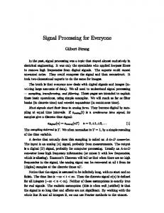
guaranteed that the graph is “defective” in the sense that there is no schedule that achieves indefinite (infinite) execution, deadlock-free operation, and bounded memory requirements [11]. When implementing an SDF graph, the periodic schedule has a large impact on most key implementation metrics, including code size, performance, and buffer memory requirements. However, the set of minimal periodic schedules grows combinatorially with the size of the SDF graph, and except for very simple examples, evaluating periodic schedules by exhaustive search is not feasible. In fact, in most practical contexts, deriving an optimal periodic schedule is computationally intractable, and this has lead to a large body of work on the development of efficient heuristics for optimized construction of periodic schedules, as well as on the study of problems, such as memory allocation and synchronization optimization that are associated with the implementation of SDF graphs through periodic schedules (e.g., see [13], [14] for overviews of many such methods). VI. MULTIPROCESSOR IMPLEMENTATION Direct implementation of a periodic schedule results in sequential execution of the dataflow graph. When implementing such a sequential execution, the application structure exposed by an SDF representation is valuable for streamlining metrics such as code size, buffer memory requirements, latency, and throughput. For implementation of high performance signal processing applications, however, a multiprocessor implementation may be preferable to a sequential solution. In this case, a parallel form of periodic schedule may be employed where the set of actors is partitioned across the set of available processors; the subset of actors assigned to each processor is ordered into a sequential schedule for that processor; and special actors for interprocessor communication and synchronization are inserted at each point where an actor sends data to or receives data from an actor that has been mapped to another processor. Before constructing such a multiprocessor SDF schedule, it is useful to convert the SDF graph into an expanded form that more fully exposes the concurrency available across actor executions. This expanded form is called the homogeneous SDF equivalent graph or simply HSDF equivalent graph of the original SDF graph. As the name implies, the HSDF equivalent graph is a homogeneous SDF graph, as defined in Section IV. Each actor in the HSDF equivalent graph corresponds to a single execution of an actor within a minimal periodic schedule for the original graph. Thus, when constructing the HSDF equivalent graph, each actor A in the original SDF graph is effectively “expanded” into qA distinct actors A1 , A2 , . . . , AqA , which represent successive executions of A. Each edge in the original graph is expanded in a similar way. This expansion can also be done in a simple, systematic way, but due to space constraints, we omit the details here and refer the reader to [13] for details. An illustration of the derivation of an HSDF equivalent graph is shown in Figure 2. Figure 2(a) shows an SDF graph
that consists of three actors A, B, and C. Each edge e is annotated with its associated production and consumption values prd (e) and cns(e). These annotations tell us, for example, that actor A produces two data values onto its output edge per execution, and actor B consumes one data value from one of its input edges and two data values from the other. The repetitions vector components for this graph are qA = 1, qB = 2, and qC = 4. Therefore, the HSDF equivalent graph contains a total of 1 + 2 + 4 = 7 actors, as shown in Figure 2(b). Similarly the edge set “expands” from four edges in the original SDF graph into a set of many edges in the HSDF equivalent graph. Some of the SDF edges in the HSDF equivalent graph contain delays. Since each actor executes only once in an HSDF graph (the repetitions vector components are always equal to one), a delay in an HSDF graph represents a data dependence that crosses iterations of the graph. Thus, for example, the unit delay on (C4 , B) tells us that data produced by actor C4 is consumed by actor B in the following graph iteration. The HSDF equivalent graph shows explicitly the data dependences across different actor executions as they execute. For example, the unit-delay, cyclic path (C1 → C2 → C3 → C4 → C1 ) indicates that all executions of SDF graph actor C must be carried out sequentially with respect to one another. This requirement is a result of the self-loop edge (C, C) shown in Figure 2(a). On the other hand, as shown in Figure 2(b), both executions B1 and B2 can be executed in parallel. From the HSDF equivalent graph, a closely-related graph called the acyclic precedence expansion graph (APEG) is derived by simply removing all edges that contain one or more delays. This is illustrated in Figure 2(c). The APEG shows the dependences between actor executions within a given iteration of the original SDF graph. The APEG is equivalent to a form of graph commonly known as task graphs. An extensive body of literature exists for mapping task graphs into minimum-latency schedules on multiprocessors [15], and through the conversion from general SDF graphs to their equivalent APEGs, such techniques can be applied to derive low-latency, parallel implementations. When other objectives, such as throughput and power consumption, are important, however, minimum-latency task graph scheduling techniques may not be as useful. An active topic of research is the development of novel multiprocessor scheduling techniques to handle the broader range of implementation metrics, such as the aforementioned objectives of throughput and power consumption, that are relevant in embedded systems. For such techniques, the APEG (task graph) is usually not the best representation to work with. Instead, the HSDF equivalent graph is more useful because it contains information about both intra- and inter-iteration dependencies in the graph. VII. FIELD-PROGRAMMABLE GATE ARRAYS Field-programmable gate arrays (FPGAs) are an attractive implementation platform for many control systems that have
1566
SDF Graph 2
A (a)
1
B
2 2
purpose buffers are conventionally used.
D
1
D
1
C
1 1
VIII. SUMMARY
D
This paper has reviewed methods for optimization of signal processing software that are useful for maximizing the performance and reliability, and minimizing the cost of controller implementations. Such techniques are used today at various levels of abstraction in computer-aided tools for design of signal processing systems, particularly in the domain of digital communications. The constraints and optimization objectives in this domain are significantly different, however, compared to those that control system designers face. The development of methods that are more oriented to the signal processing requirements of control systems, and the integration of such methods into control system design tools are important topics for further work.
HSDF Equivalent Graph C1
B1
(b) A
D
B2 Acyclic Precedence Expansion Graph B1 A (c)
C2
D
D
C3 C1
C4
C2 B2
R EFERENCES
C3 C4
Fig. 2. An example to illustrate derivation of the HSDF equivalent graph, and the associated acyclic precedence expansion graph.
high performance requirements, but do not have tight constraints on power consumption. FPGA devices, such as the Xilinx Spartan series and the Altera Stratix series devices, are made up of large networks of programmable hardware structures for combinational logic; interconnect; input-output; and selected, special-purpose computations [16]. Recent FPGAs, such as the Xilinx Virtex-4 SX devices, contain streamlined accelerators for speeding up signal processing functions. Dataflow representations and related forms of program representation are useful for mapping signal processing applications onto FPGAs. The Compaan/Laura toolset, developed at Leiden University, is a software environment that demonstrates this. Compaan/Laura derives FPGA implementations from a restricted class of MATLAB programs [17]. This restricted class of programs is known as parameterized, static nested loop programs. Compaan/Laura employs an intermediate representation based on the Kahn process network (KPN) model of computation, which is closely related to dataflow. As described in Section III, the KPN model is a general model of data-driven computation, and SDF, and dataflow process networks (in the form that they are used in signal processing) are special cases of the KPN model. An example of an optimization technique in the Compaan/Laura toolset is its set of dependence analysis mechanisms that determines the most specialized form of buffer implementation, with respect to reordering and multiplicity of buffered values, for implementing communication between KPN modules [18]. This allows specialized buffers to be implemented in many cases where less efficient, general-
[1] G. Walsh, O. Beldiman, and L. Bushnell, “Asymptotic behavior of nonlinear networked control systems,” IEEE Transactions on Automatic Control, vol. 46, no. 7, July 2001. [2] G. Walsh, O. Beldman, and L. Bushnell, “Error encoding algorithms for networked control systems,” Automica, vol. 38, pp. 261–267, 2002. [3] G. Walsh, H. Ye, and L. Bushnell, “Stability analysis of networked control systems,” IEEE Transactions on Control Systems Technology, vol. 10, no. 3, May 2002. [4] D. Hristu-Varsakelis, “Feedback control with communication constraints,” in Handbook of Networked and Embedded Systems, D. Hristu-Varsakelis and W. S. Levine, Eds. Birkhauser Boston, 2005. [5] L. Auslander, T. Kailath, S. Mitter, J. W. Helton, and F. A. Grunbaum, Signal Processing: Control Theory and Applications. Springer-Verlag, 1990. [6] P. Caspi and O. Maler, “From control loops to real-time programs,” in Handbook of Networked and Embedded Control Systems, D. HristuVersakelis and W. Levine, Eds. Birkhauser Boston, 2005. [7] G. Agha, Actors: A Model of Concurrent Computation in Distributed Systems. MIT Press, 1986. [8] S. S. Bhattacharyya, R. Leupers, and P. Marwedel, “Software synthesis and code generation for DSP,” IEEE Transactions on Circuits and Systems — II: Analog and Digital Signal Processing, vol. 47, no. 9, pp. 849–875, September 2000. [9] E. A. Lee and T. M. Parks, “Dataflow process networks,” Proceedings of the IEEE, pp. 773–799, May 1995. [10] G. Kahn, “The semantics of a simple language for parallel programming,” in Proceedings of the IFIP Congress, 1974. [11] E. A. Lee and D. G. Messerschmitt, “Synchronous dataflow,” Proceedings of the IEEE, vol. 75, no. 9, pp. 1235–1245, September 1987. [12] G. Bilsen, M. Engels, R. Lauwereins, and J. A. Peperstraete, “Cyclostatic dataflow,” IEEE Transactions on Signal Processing, vol. 44, no. 2, pp. 397–408, February 1996. [13] S. Sriram and S. S. Bhattacharyya, Embedded Multiprocessors: Scheduling and Synchronization. Marcel Dekker, Inc., 2000. [14] P. K. Murthy and S. S. Bhattacharyya, Memory Management for Synthesis of DSP Software. CRC Press, 2006. [15] Y. Kwok and I. Ahmad, “Static scheduling algorithms for allocating directed task graphs to multiprocessors,” Journal of the Association for Computing Machinery, vol. 31, no. 4, pp. 406–471, December 1999. [16] W. Wolf, FPGA-Based System Design. Prentice Hall, 2004. [17] T. Stefanov, C. Zissulescu, A. Turjan, B. Kienhuis, and E. Deprettere, “System design using Kahn process networks: the Compaan/Laura approach,” in Proceedings of the Design, Automation and Test in Europe Conference and Exhibition, February 2004. [18] A. Turjan, B. Kienhuis, and E. Deprettere, “Approach to classify inter-process communication in process networks at compile time,” in Proceedings of the International Workshop on Software and Compilers for Embedded Systems, September 2004.
1567