KSCE Journal of Civil Engineering (2014) 18(2):488-496 Copyright ⓒ2014 Korean Society of Civil Engineers DOI 10.1007/s12205-014-0552-9
Geotechnical Engineering
pISSN 1226-7988, eISSN 1976-3808 www.springer.com/12205
TECHNICAL NOTE
Optimization of Soil Nailing Design Considering Three Failure Modes Hyung-Joon Seo*, In-Mo Lee**, and Seok-Won Lee*** Received November 8, 2012/Accepted April 15, 2013/Published Online Janunary 1, 2014
··································································································································································································································
Abstract Soil nailing is a reinforcing method using the shear strength of in-situ ground and the pullout resistance of soil nailing. In the current korean slope design standard, only the pullout failure and the shear failure are considered as the main design factors. However, in the slope of an actual construction site, multi-face excavation is executed rather than full face excavation, and face failure can therefore occur in each excavation step due to the decrease of confining pressure on the excavation face during the topdown excavation. Therefore, it is necessary to include face failure as the main design factor in the slope design. This study verifies theoretically the mechanical behavior of face failure as well as pullout failure and shear failure. The constrained conditions for each failure mode are defined, and the optimization of soil nailing design is proposed on this basis. The design variables considered for the three failure modes are the bonded length of nail, the number of nails, and the prestress. These three design variables are estimated from the optimization design procedure proposed in this study considering constrained conditions. As the optimization design procedure of soil nailing proposed in this paper considers not only the pullout and shear failures but also face failure, it could be a more satisfactory design procedure in the actual field. Keywords: soil nailing, shear failure, pullout failure, face failure, prestress ··································································································································································································································
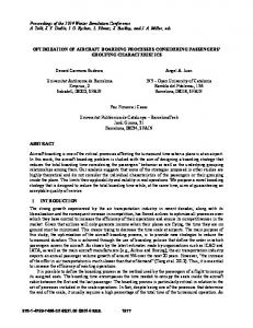
1. Introduction Soil nailing is a reinforcing method using the shear strength of in-situ ground and the pullout resistance of soil nailing by inserting the nail (reinforcing material) into the ground and unifying it with the ground through grouting (Xue et al., 2011; Su et al., 2007; Pradhan et al., 2006; Yin and Su, 2006; Junaideen et al., 2004). It is a passive method because it resists only when a ground displacement occurs. On the other hand, the anchor method restricts the initial ground displacement by applying the prestress in advance. In both methods, the skin friction between ground and grouting and the tensile yield load of the inserted reinforcing material are considered as the main resistances in the design. Tan and Chow (2004) classified the failure mode of ground inside the slope as pullout failure, shear failure, and face failure. Turner and Jensen (2005) then carried out field tests on the basis of these three failure modes. The Federal Highway Administration (FHWA, 1998) of USA defined the three failure modes according to failure surface as shown in Fig. 1. Pullout failure is caused by the deficiency of skin friction between ground and grouting, and shear failure is caused by the deficiency of the tensile yield load of reinforcing material. In the current korean slope design standard (KISTEC, 2006), only the pullout failure and the shear failure are considered as the
main design factors. However, in the slope of an actual construction site, multi-face excavation is executed rather than full face excavation, and a face failure can therefore occur in each excavation step due to the decrease of confining pressure on the excavation face during the top-down excavation. In face failure, the ground begins to fall away from the excavation face to the final total failure surface continuously as shown in Fig. 1. In this case, a method such as prestress is required to apply the confining pressure onto the excavation face. Therefore, it is necessary to include face failure as the main design factor in the slope design. This study verifies theoretically the mechanical behavior of face failure as well as pullout failure and shear failure. The constrained conditions (stability analysis) for each failure mode are defined, and the optimization of soil nailing design is proposed on this basis. The design variables considered for the three failure modes are the bonded length of nail, the number of nails, and the prestress. These three design variables are estimated from the optimization design procedure proposed in this study considering the constrained conditions. As this study includes not only the bonded length of the nail and the number of nails but also the prestress, the face failure in each excavation step can be considered in the optimization design procedure.
*Ph.D., School of Civil, Environmental and Architectural Engineering, Korea University, Seoul 136-713, Korea (E-mail:
[email protected]) **Member, Professor, School of Civil, Environmental and Architectural Engineering, Korea University, Seoul 136-713, Korea (E-mail:
[email protected]) ***Member, Professor, Dept. of Civil and Environmental System Engineering, Konkuk University, Seoul 143-701, Korea (Corresponding Author, E-mail:
[email protected]) − 488 −
Optimization of Soil Nailing Design Considering Three Failure Modes
assumed as 45+φ/2 as shown in Fig. 7. However, this plane wedge failure mechanism can be transferred to other failure mechanisms such as log spiral mechanism. Main purpose of this paper was to suggest overall flow of optimization of soil nailing design. Therefore, plane wedge failure mechanism which is relatively simple model was used in this study. In Fig. 2, l1~ln refers to the nail length inside the failure surface; smin refers to the minimum center to center distance between nails; Wtot is the total soil weight inside the total failure surface; L is the longitudinal length of excavated plane; H is the excavation depth; and Z is the horizontal distance from the excavation surface to total failure surface at the ground surface.
Fig. 1. Three Failure Modes
2. Constrained Conditions for Three Failure Modes The aim of this study is to propose an optimization design procedure that considers all three failure modes in a vertical slope such as a retaining wall. To define the constrained conditions for each failure mode, a theoretical review was first conducted. For the pullout and shear failures, the resistances (skin friction and tensile strength of reinforcing material) were theoretically verified as shown in Fig. 1, to determine whether the resistances could hold the ground (soil wedge) on the potential total failure surface. In the case of face failure with multi-face excavation, as the potential failure surface can change in each excavation step, a theoretical review was carried out on the failure surface of each excavation step (rather than on the potential total failure surface) to estimate the confining pressure (such as prestress) on the excavation surface, as a design variable. Finally, by using the optimization design procedure which was induced on the basis of constrained conditions derived from each failure mode, the design variables such as bonded length of nail (X1), number of nails (X2), and confining pressure on excavation surface were estimated (see Fig. 2). In this study, Rankine earth pressure theory (Rankine, 1857) was used and thus the angle of failure surface (θ) in the vertical slope was
2.1 Constrained Condition for Pullout Failure In soil nailing, the grouting is conducted after drilling the ground to resist the pullout failure through the skin friction between the ground and the grouting. The resistance to pullout failure can be divided into two elements. The first element is the resistance by shear strength (c, φ) of the ground itself (resistive weight by shear strength) against the total soil weight (Wtot) that causes the slope failure as indicated in (i) of Fig. 3. If the shear strength of ground is larger than the shear stress by soil weight, the stability is maintained and no reinforcement is needed. Otherwise, reinforcement such as soil nailing or anchor method is required. When the resistive weight by shear strength (c, φ) is subtracted from the total soil weight (Wtot), the residual soil weight (Wresidual) can be obtained as in Eq. (1). W residual
H cL ---------- tanφ + W tot cosθ tanφ sinθ = W tot sinθ – ------------------------------------------------------------------FS1
(1)
Here, θ is 45+φ/2, φ is the internal friction angle, c is the cohesion, and FS1 is the safety factor for the slope. The second element of the resistance to pullout failure is the resistance by skin friction (Tskin) of soil nailing as indicated in (ii) of Fig. 3, which can be calculated with Eq. (2). DπX1 X2 Tskin = τ f -----------------FS2
(2)
Here, τf refers to the unit skin friction and FS2 is the safety factor for pullout failure.
Fig. 2. Design Variables in Optimization of Soil Nailing Design Vol. 18, No. 2 / March 2014
Fig. 3. Pullout Failure on Total Failure Surface − 489 −