This "fuzzy set" or membership function can take various shapes (bell-curve, trapezoidal, triangular, and other). X is X2. Rule 1: if X is X1 and Y is Y1, then Z is Z1.
Optimization of Synchrotron Beam Alignment using a Linguistic Control Scheme Roberto Pugliese and Roberto Poboni* Electronic Technology Laboratory, Scientific Division, Sincrotrone Trieste. *Department of Electrotechnics, Electronics and Informatics, University of Trieste. Abstract: The project deals with the design and the implementation of an adaptive controller which optimizes the beam alignment at the SuperESCA beamline, using a behavioural model based on fuzzy logic. The operating environment is an extension of the FuzzyCLIPS1 expert system shell, integrated in the ELETTRA Beamline Control System.
1. INTRODUCTION The Sincrotrone Trieste is a research laboratory which built ELETTRA, a “third generation” machine, with a 2GeV state-of-the-art storage ring. ELETTRA is a high brilliance synchrotron radiation facility covering a large spectrum of wavelength from the VUV to hard X-ray region. This radiation can be used for chemical, physical and biological experiments. According to the requirement of the experiments, the light has to be collimated, monochromatized and focussed on the sample under test; this is realized by a highly sophisticated beamline working in ultra-high vacuum. The Super-ESCA beamline [1] has been designed for high-resolution core-level spectroscopy using soft x-ray synchrotron radiation. It receives the light from an undulator in the storage ring ELETTRA. The tunability of this insertion device and the connected SX700 monochromator allow experiments in the photon energy range 1001400eV. This beamline, operational since 1994 has shown a resolving power varying from 10000 to 8000 for photon energies between 240 and 850 eV. The performance of the Super-ESCA beamline is strongly affected by the alignment conditions i.e. all the optical components must be set to optimize the flux and resolving power at the experimental station. The propagation process of the photon beam through the beamline has a complex structure. Many optimization schemes can be applied under the assumption of the existence of a mathematical model of the process [12]. However such a model may be too complex, it may not be precise or it may not even exist. Soft Computing methodologies such as neural networks, genetic algorithms, and fuzzy sets theory have been applied to a broad class of such real-world problems. In this work, optimizing control is performed by using a rule-based look-up table which can be learned from operating experience without the need of a process model.
1 FuzzyCLIPS was developed by the Knowledge System Laboratory, National Research Council of Canada
2. THE BASICS OF FUZZY LOGIC Fuzzy logic introduced by Lofti Zadeh [2,3] brings reason to the vagueness found in human experiences or to the unclear boundaries in physical processes. For example, even a concept like "normal height" is difficult to express by standard "crisp" computing, but easily described by a characteristic function that has a continuous grade between 0 and 1. This "fuzzy set" or membership function can take various shapes (bell-curve, trapezoidal, triangular, and other). Rule 1:
if
X is X1
Y is Y1,
Y is Y1
X is X1
1
and
then
Z is Z1 Z is Z1
1
0.4 0.2
0
0
Rule 2: 1
X is X2
if
X is X2
and
Y is Y2,
Y is Y2
then 1
Z is Z2 Z is Z2
0.8 0.6
0
0
1
X is x
Y is y
fuzzy inference inputs
0
center of gravity location fuzzy inference ouput
Z is z
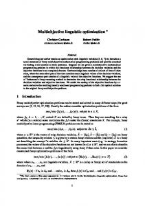
Fig.1: Stages of Fuzzy Processing
Fuzzy Logic theory allows one to work on a linguistic description of the reality, representing information by linguistic variables. Linguistic variables are entities whose values are fuzzy sets. Fuzzy Logic represents a new approach to system modeling. The first known applications of Zadeh's theory were reported by Mamdani [4,5] .
The stages of fuzzy processing are illustrated in Fig.1 for a simple case of two linguistic variables (X,Y) combined by means of two rules to form the result Z. Inputs are compared to membership functions by a process called "fuzzification", so a membership grade is assigned to each linguistic term. Logic combinations of linguistic terms are then evaluated by application of Fuzzy Logic operators: usually the minimum grade of the conditions is selected as the fitness grade of the rule left-hand side. Fuzzy values of the rule right hand side are adjusted to reflect the rule fitness grade and then combined with the fuzzy values of the other rules. Center of gravity or other averaging methods are used for "defuzzyfication", that is, to obtain a single value for each output variable. Many implementations of this kind of inference can be found in literature [9]. So far Fuzzy Logic has been exploited mainly in Knowledge Based Systems and in Control Systems [6-8]. We say that a control system is "fuzzy" when the value of the controlled variables is determined by the input signals through a fuzzy inference. In the same way we talk about Fuzzy Optimization when the optimization process is driven by fuzzy inference.
3. THE PROBLEM STATEMENT The schematic diagram in Fig.2 is a simplified description of the beamline Super-ESCA. In the drawing only the components relevant to the optical alignment are present; optical components are represented with rounded border. A detailed discussion of each component of the beamline is beyond the scope of this document, but to feel the complexity of the system requires a brief description of the beam path. As the synchrotron radiation beam leaves the undulator, it passes through two photon Beam Position Monitors and then through the Double Slits where the central part of the beam is selected; it then reaches the Switching Mirror, a plane mirror used to switch between the branch lines2 . Before reaching the SX700 Monochromator, the light beam passes the Prefocusing Mirror, a cylindrical mirror which focusses the beam in the vertical plane onto the Entrance Slit. The Monochromator is the most complex optical component of the beamline, consisting of a plane mirror, a plane grating and an elliptical focusing mirror. The plane grating spreads the incoming radiation in the vertical plane according to energy. Only one selected energy follows the right path to the elliptical mirror, which focusses the radiation on the Exit Slit. The Refocussing Mirror, an elliptical mirror, refocusses the monochromatized light onto the sample in the Experimental Chamber. A photo-diode supplies a signal proportional to the quantity of photons leaving the Exit Slit. The complexity of the optical path makes it difficult to determine the equations relating the quality of the synchrotron light spot at the experimental chamber with the position of the optical components of the beamline. One may realize that the alignment optimization, that is the process of setting the positions of all the optical components to optimize the flux and resolving power at the experimental station, is a very difficult. In practice it is several hour job for a pair of trained operators.
2 The Super-ESCA and ESCA-microscopy beamlines share the so-called "front-end", i.e. the part of the beamline
from the source to the switching mirror.
Undulator BPMs Double Slits Switching Mirror Prefocus. Mirror Entr. Slit Monocrom. SX700 Exit Slit Photodiode Refocus. Mirror
Experimental
station
Fig.2: Simplified scheme of the Super-ESCA Beamline
The problem we have actually considered, a non-trivial subproblem of the global alignment optimization, can be formalized as follows: determine the positions of Prefocussing and Switching mirrors which maximize the flux of photons at the photo-diode, assuming that the Monochromator is aligned. Namely, we have considered only the degrees of freedom of the mirrors which can be considered optically critical: the Pitch and the Roll angular positions. Formally we have to find the maximum of the following function:
y = f(x1,x2,x3,x4) where y is the photo-diode current, x1 is the Switching Mirror Pitch, x2 is the Switching Mirror Roll, x3 is the Prefocusing Mirror Pitch and x4 is the Prefocussing Mirror Roll.
4. THE OPERATING ENVIRONMENT The Beamline Control System [14] provides supervision and control of the beamline equipment: it has the responsibilities to assure a "safe behaviour of the beamline" and to give the operator a uniform access to the
instrumentation. The system has a distributed multi-layer architecture (Fig.3). The presentation level is based mainly on UNIX graphical workstations (such as DEC-ultrix, DEC-alpha, HP9000): a synoptic interface implemented with DataViews3 and Motif enables graphical navigation through the beamline instrumentation.
WS
WS
PC
RPC, TCP/IP
BCS Beamline Equipment
VME
EIB EIB EIB EIB
Fig.3: The Beamline Control System architecture
The core of the system, called BCS, is the process control level, based on VME embedded systems using the Motorola 68030 processor (MVME147) and the LynxOS real-time operating system. These two layers are connected by an ethernet LAN via Remote Procedure Calls4. The equipment interface level, connected with the BCS by the VME bus, is based on standard data acquisition boards 5. The application software can be developed both at the presentation level and at the process control level by means of well defined libraries.
3 Is a graphical visualization package developed by V.I. Corporation 4 In the current release the CERN network compiler has been used. 5 We have named such boards Equipment Interface Boards (EIB).
FuzzyCLIPS is an extended version of the CLIPS rule-based shell6 for representing and manipulating fuzzy facts and rules. In addition to the CLIPS functionality, Fuzzy CLIPS can deal with exact, fuzzy, and combined reasoning, allowing fuzzy and normal terms to be mixed freely in the rules and facts of the knowledge based system. The system uses two basic inexact concepts, fuzziness and uncertainty. We have developed an extended version of FuzzyCLIPS which allows one to perform the basic read and write actions on the BCS controlled variables. The optimization application was implemented at the process control layer.
5. THE FUZZY OPTIMIZER The design of the optimizer was guided by the domain knowledge of the expert operator and by the analysis of the qualitative behaviour of the objective function; an operational model of the beamline was implemented with the Ray Tracing Shadow7 simulation program.
OC
Ia
A(k)
S(k-1)
∆ y / ∆ x (k)
F
Iu
U(k)
S(k)
*
D
∆ x (k+1)
+
x(k)
Optical System
Fig.4: Simplified block diagram of the controller.
The optimization control scheme we have developed is a modified version of the linguistic control scheme developed
6 CLIPS was developed by the Artificial Intelligence Section, Lyndon B. Johnson Space Center, NASA. 7 Ray Tracing Shadow was developed by the University of Wisconsin.
by Procyk and Mamdani [10,11]. The independent variables, namely the mirror positions, are optimized in a sequence determined by a knowledge based planner. Each variable is optimized by a sophisticated hill climbing technique: a simplified block diagram is shown in Fig.4. At each step the block F processes the slope of the objective function by performing normalization and fuzzification. The block Iu takes the normalized slope at the current and previous step and by fuzzy inference provides the magnitude of the correction of the mirror position (angle change) which is then defuzzyfied by block D. The direction of the correction is determined in the natural way by the sign of the current slope. If we call S(k) the normalized slope and U(k) the angle change, a typical linguistic rule can then be written in the following form:
if S(k) is Si and S(k-1) is Sj then U(k) is Uh.
The fuzzy sets of the normalized slope and angle change are shown in Fig.5. The linguistic rule set can be
Membership grade
represented by the relation matrix or look-up table of Fig.6.
1.0
Z
S
M
0.20
0.40
VB
B
0.5
0.0 0.00
0.60
0.80
1.00
Membership grade
Normalized slope
1.0
Z
VS
S
M
B
VB
0.60
0.80
0.5
0.0 0.00
0.20
0.40
1.00
Normalized angle change
Fig.5: Normalized slope (S) and angle change (U) membership functions. The labels can be read as follows: Z as zero, VS as very small, S as small, M as medium, B as big and VB as very big.
We have also introduced an adaptive component in the fuzzy controller. The method described in Maeda-Murakami [13] consists of realizing an adjustment function which determines, depending on the operational conditions of the controller, a scaling factor for the angle change. As shown in the block diagram shown in Fig.4, the module Ia takes
the normalized slope at the current and previous step and depending on the operational conditions OC, determines by fuzzy inference the scaling factor A(k). A knowledge based module sets OC by observing the optimization process.
U(k)
S(k)
S(k-1) n.a.
Z
S
M
B
VB
Z
VS
Z
Z
VS
Z
VS
S
VS
Z
VS
VS
VS
Z
M
S
VS
S
M
VS
S
B
M
S
VB
B
B
S
VB
S
M
B
M
M
S
Fig.6: Linguistic control rules
An example of the behaviour of the controller with and without the adaptive component is shown in Fig.7; the performance gain provided by the adaptive module is generally valuable.
6
4
3
2 normal adaptiv e
1
step
Fig.7 the behaviour of the optimizer
29
27
25
23
21
19
17
15
13
11
9
7
5
3
0
1
photo-diode
current
(uA)
5
6. CONCLUSION We have implemented an adaptive controller which optimizes the beam alignment at the beamline SuperESCA by using a behavioural model based on the fuzzy logic. The system is now under test and its behaviour is quite satisfactory both on the simulator and in the field. Further improvements could be obtained by using the beam status information provided by the Beam Position Monitors; fuzzy logic could be used as a tool to implement a qualitative optical reasoning component. The introduction of soft computing techniques can be considered a meaningful step in the extension of the application areas of the Beamline Control System.
Acknowledgements Special thanks are due to the staff of the beamline Super-ESCA, in particular to Daniele Cocco and to the staff of the Electronic Technology Laboratory, in particular to Rudi Sergo and Fulvio Billè.
References [1] W.Jark, Soft X-ray monochromator configuration for the ELETTRA undulator - Rev.Sci.Inst. 63(1) 1992. [2] L.A.Zadeh, Fuzzy Sets - Inform. Control 8, 1965, pag. 338,353. [3] L.A.Zadeh, Outline of a new approach to a new analysis of complex system and decision processes - IEEE trans. on Syst. Man and Cybernetics, 3/1973, pag. 28-34. [4] E.H.Mamdani, Assilian, A fuzzy logic controller for dynamic plant - Int. J. Man-Machine Stud. 7, 1975, pag.113. [5] E.H.Mamdani, Application of fuzzy algorithms for control of simple dynamic plant - Proc. IEEE 212, 1974, pag. 1585-1588. [6] R.Scattolini, N.Schiavioni, Introduzione al Controllo fuzzy - Automazione e Strumentazione, Aprile 1993, pag. 67 - 73. [7] G.A.Magnani, Esempi di applicazione nei sistemi di controllo - Automazione e Strumentazione, Giugno 1993, pag. 83 - 88. [8] L.X.Wang, M.Mendel, Generating fuzzy rules by learning from examples - IEEE transaction on System, Man, and Cybernetics, vol. 22, No. 6, november/december 1992, pag. 1414 - 1427. [9] J. and S.R. Jang, ANFIS: Adaptative-Network-Based Fuzzy Inference System - IEEE transaction on System, Man, and Cybernetics, vol. 23, No. 3,1993 pag. 665 - 685. [10] T.J.Procyk and E. H. Mamdani, A linguistic self-organizing process controller - Automatica, 15, (1979), 15. [11] S.S. Jang, D.S.H.Wong and C.K.Liau, On-line/off-line optimization of complex processes using a linguistic self-organized optimizing control scheme - Fuzzy sets and systems, 47, (1992), pag. 23 - 33. [12] G.V.Reklaitis, A.Ravindran and K.M.Ragsdell, Engineering Optimization: Methods and Applications - a Wiley-Interscience Pubblication, John Wiley and sons. [13] M.Maeda and S.Murakami, A self-tuning fuzzy controller - Fuzzy sets and systems 51, 1992, pag. 29 - 40. [14] A.Abrami, F.Gagliardi, A.Galimberti, A.Savoia, The ELETTRA Beamlines Control System - ST/S-TN-92/9, 1992.