TRK-11 TOC
Proceedings of ASME Turbo Expo 2004 Power for Land, Sea, and Air June 14-17, 2004, Vienna, Austria
GT2004-53346
OPTIMIZATION OF THREE-DIMENSIONAL ANGLED RIBS WITH RANS ANALYSIS OF TURBULENT HEAT TRANSFER Hong-Min Kim
Kwang-Yong Kim
Graduate School of Mechanical Engineering Inha University Inchon 402-751 Korea
[email protected]
School of Mechanical Engineering Inha University Inchon 402-751 Korea
[email protected]
ABSTRACT A numerical optimization procedure for the shape of threedimensional channel with angled ribs mounted on one of the walls to enhance turbulent heat transfer is presented. The response surface based global optimization with Reynoldsaveraged Navier-Stokes analysis of fluid flow and heat transfer is used. Shear stress transport (SST) turbulence model is used as a turbulence closure. Computational results for local heat transfer rate show a reasonable agreement with the experimental data. The pitch-to-height ratio of the rib and rib height-to-channel height ratio are set to be 9.0 and 0.1, respectively, and width-to-rib height ratio and attack angle of the rib are chosen as design variables. The objective function is defined as a linear combination of heat-transfer and frictionloss related terms with the weighting factor. Full-factorial experimental design method is used to determine the data points. Optimum shapes of the channel have been obtained in the range from 0.0 to 0.1 of the weighting factor.
detailed information about the variation of local velocities and Nusselt number, and concluded that the average heat transfer enhancement over the floor gave a maximum for rib pitch-toheight ratio, Pi/H = 9. In the experimental work of Han et al. [2], the effects of rib angle of attack (α = 30°, 45°, 60° and 90°) and rib pitch-to-height ratio (Pi/H = 10, 20) on the pressure drop and the average heat transfer coefficients in the fully developed turbulent air flow in a square duct with two opposite rib-roughened walls have been investigated. At the angle of attack of 75°, maximum heat transfer coefficient was achieved, and friction factor for Pi/H = 20 was smaller than that for Pi/H = 10. Thermal performance which is defined as a ratio of heat transfer coefficient to friction factor reached its maximum at angles of attack of 30° and 45° for both Pi/H ratios, and correlations for average friction factor and average heat transfer coefficient have been obtained. Local heat transfer and friction loss in a square duct roughened by various types of continuous and discrete rib turbulators were examined by Cho et al. [3]. They recommended 90° in-lined array for high thermal performance. In addition to the experimental works, many numerical researches [4~6] were performed to predict fluid flow and heat transfer in a ribbed channel and most of them were confined to compare the accuracy of the various turbulence models, not to find the optimal shape of the rib. In many experimental and numerical works, the main purpose was to observe the effect of angle of attack and rib pitch-to-height ratio on the heat transfer coefficient and friction factor, and also to find the optimal case which gives the best thermal performance among a few tested cases. Thus, the optimal shape of rib-roughened channel, considering wide ranges of geometric variables, was not suggested. But, Kim and Kim [7] presented an investigation on numerical optimization technique coupled with Reynolds-averaged Navier-Stokes analysis of turbulent flow and heat transfer for the design of
INTRODUCTION Attachment of ribs to flow passages becomes one of the widely used means of heat transfer enhancement, and has many industrial applications including internal cooling of turbine blades. Artificial ribs attached on the surface increase production of turbulent kinetic energy, but cause extra flow resistances. Thus, to optimize the shape of rib-roughened surface, it is indispensable to compromise between augmentation of heat transfer and reduction of friction drag. Many experimental works have been carried out to develop high-performance heat transfer surfaces roughened by square ribs for various heat exchanging devices. Rau et al. [1] performed aerodynamic and heat transfer measurements in a square channel with single surface roughened by ribs presenting significant blockage ratio (H/Dh = 0.1) and being perpendicular to the main flow direction. They reported the
1
Copyright © 2004 by ASME
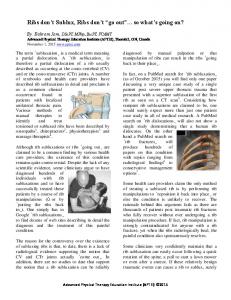
rib-roughened surface in case of single surface roughened in two-dimensional channel. They suggested the optimal values of W/H and Pi/H with the objective function defined as linear function of heat transfer coefficient and friction drag coefficient, and showed that the numerical optimization method is a quite effective and reliable way of designing heat transfer surface. With the aid of high performance computers, numerical optimization techniques have been developed rapidly for the last decade. Among the methods of numerical optimization, response surface method [8], as a global optimization method, has many advantages over the gradient-based methods [7, 9]. Recently, the response surface based optimizations are being applied to many single- and multi-disciplinary optimization problems [10, 11]. In this work, a numerical optimization procedure is presented for the design of heat transfer surface roughened by square ribs in a three-dimensional channel with single surface roughened. Turbulent convective heat transfer is analyzed with Reynolds-averaged Navier-Stokes analysis. Response surface based optimization method is employed to optimize two design variables, i.e., width-to-height ratio and angle of attack of the rib. Objective function is defined as a linear combination of heat transfer and friction drag coefficients with the weighting factor. NOMENCLATURE B width of the channel [=0.05 m] D height of the channel [=0.05 m] Dh channel hydraulic diameter [=0.05 m] F objective function f friction factor f0 reference friction factor H rib height [=0.005 m] Nu local Nusselt number Nua average Nusselt number divided by Nus Nus reference Nusselt Number Pi rib pitch [m] ∆p pressure drop in a channel [Pa] qo wall heat flux [=600 W/m2] Re Reynolds number average axial velocity at inlet [=9.27 m/s] U W width of the rib [m] Greek symbols α angle of attack [°] β weighting factor in objective function fluid density [=1.185 kg/m3] ρ NUMERICAL ANALYSIS For the analysis of convective heat transfer in a ribroughened three-dimensional channel, commercial CFD code, CFX-5.6, was used in this work. It solves the Reynoldsaveraged Navier-Stokes equations (RANS) with high
D
z y
α
x
B
Air W
Pi
H
Fig. 1 Rib arrangement resolution scheme for advection term and Rhie-Chew interpolation for the pressure-velocity coupling. The linear solver uses an algebraic multigrid method based on the additive correction multigrid strategy, and fully coupled momentum and energy equations are solved simultaneously. SST turbulence model with scalable wall functions [12] is used as a turbulence closure. Basically, SST model combines the advantages of the k-ε and k-ω models with a blending function. The k-ω model is activated in the near-wall region and the rest region uses the k-ε model. It is demonstrated that the SST model captures separation under adverse pressure gradient well compared to other eddy viscosity models, and thus, predicts well the nearwall turbulence that is vital to the accurate prediction of the turbulent heat transfer [13]. The computational domain in which five ribs are included has the length of 2Dh both upstream and downstream from the first and last ribs, respectively, as shown in Fig. 1, where attack angle of 90 degrees implies flow normal to the ribs. At the inlet, unform velocity was specified, and turbulence intensity was assumed to be 5 percents. And, at the outlet of the domain, atmospheric pressure was given. Numerical work of Iaccarino et al. [14] reported that the numerical prediction shows better performance if conduction heat transfer in the rib is taken into account. In this work, for conjugate heat transfer calculation, the conduction in solid rib has been included in the analysis. Thus, constant heat flux was specified on the bottom of ribs and surfaces between the ribs. OPTIMIZATION PROCESS Response Surface Method In order to obtain an optimum shape of the rib-roughened three-dimensional channel, a numerical optimization was performed in this work. The optimization problem is defined as a minimization of an objective function F(x) with xil ≤ xi ≤ xiu, where x is a vector of design variables, and xil and xiu are lower and upper bounds of each design variable. Response surface method (RSM) [8] is to perform a series of experiments or numerical analyses, for the prescribed set of design points, and to construct a response surface of the measured quantity over the design space. When the secondorder polynomial is used, the response surface is expressed as follows.
2
Copyright © 2004 by ASME
n
n
η = c0 + ∑ c j x j + ∑ c jj x 2j + ∑∑ cij xi x j j =1
j =1
(1)
Grid 1(1.5× 10 5)
i≠ j
5
Grid 2(1.8× 10 ) 5 Grid 3(2.7× 10 ) 5 Grid 4(3.5× 10 ) 5 Grid 5(4.4× 10 )
8
Nu/Nus
where η is the response function, xi indicates design variables, and c’s are the unknown polynomial coefficients which are determined by the least square method. Efficiency of the response surface based optimization was verified by Shyy et al.[15], Papila and Shyy [16], Madsen et al. [17], and Vaidyanathan et al. [18] in their works of designing rocket engine injector, supersonic turbines, diffuser, and rocket engine component, respectively. Prescribed set of design points, so called training points, was selected by full-factorial design [8]. The three-dimensional channel with rib-roughened wall is shown in Fig. 1. With six geometric variables; height of the channel (D), width of the channel (B), height of the rib (H), width of the rib (W), pitch of the periodic ribs (Pi) and angle of attack of the rib (α), there are five dimensionless variables; H/D, B/D, W/H, Pi/H and α. In the present optimization, Pi/H, H/D and B/D were set to be 9.0, 0.1, and 1.0, respectively. And, W/H and α were used as design variables in the optimization since α was reported to affect significantly the heat transfer and friction factor by the experimental works [19] and W/H was not widely treated in the measurement.
6
4
2
0
2
4 x/H
6
8
Fig. 2 Grid dependency test 4 Rau et al.(1998) Calculation
Nu/Nus
3
2
Objective function To maximize the performance of the ribs, the optimum shape should be determined by compromising between the enhancement of heat transfer and reduction of friction loss. On this purpose, the objective function defined as follows is minimized in the optimization process.
F = FNu + βF f
1 Nu a
(3)
where
Nu a =
∫
A
Nu dA Nu s , Nu s = 0.023 Re 0.8 Pr 0.4 A
Nu was calculated on the wall between third and fourth ribs, and Nus is the Nusselt number obtained from the Dittus-Boelter correlation, which is for the fully developed turbulent flows in a smooth pipe. The friction-loss related term in equation (2) is defined as follows.
⎛ f ⎞ F f = ⎜⎜ ⎟⎟ ⎝ f0 ⎠
0
2
4 x/H
6
8
Fig. 3 Comparison of local Nusselt number
(2)
where the weighting factor, β is adjusted to the designer’s purpose. The heat-transfer related term on the right-hand side is defined as an inverse of Nusselt number.
FNu =
1
f =
∆pDh , −2 f 0 = 2(2.236 ln Re − 4.639 ) 2 ρU 2 Pi
f0 is a friction factor for fully developed flow in a smooth pipe, and is obtained from Petukhov empirical correlation [20] which is modified from the Karman-Nikuradse correlation for the best fit in the range, 104 < Re < 106. RESULTS AND DISCUSSION For grid dependency tests, five different numbers of grids are tested for the single surface roughened channel with Re=30,000, W/H=1.0, and α =45° as shown in Fig. 2. In the present study, unstructured tetrahedral grid system is used with the hexahedral at the wall region to resolve high velocity Table 1 Design variables and ranges
13
(4)
3
Design variable
Lower bound
Upper bound
α W/H
30.0° 0.5
90.0° 2.5
Copyright © 2004 by ASME
Table 2 Results of ANOVA and regression analysis β
R
R
0.02
0.997
0.993
2
8 α = 30 ° α = 60 ° α = 90 °
2
R
adj
6
Nua
0.982 4
4
2
3
Nu/Nus
0 0.5
1
1.5 W/H
2
2.5
Fig. 5 Effects of W/H on Nua
3 Ribs 4 Ribs 5 Ribs 6 Ribs
2
1
0.04 α = 30° α = 60° α = 90°
0
2
4
6
8
0.03
x/H
gradient. First grid points are placed at 0.0002D to satisfy y+ less than 1. From the results, Grid 4 with 3.5×10⁵ grids is selected as an optimum one. For the validation of present numerical solution, the results for the distribution of local Nusselt number are compared with the measurement of Rau et al. [1] at Reynolds number, 30,000 with B/D=1.0, H/D = 0.1, Pi/H = 9.0 and α =90°, in Fig. 3. The maximum value on the surface between the ribs is underestimated, but general trend of the distribution is acceptable in comparison with the experimental data. There are two methods of calculation for predicting heat transfer rate of ribbed surface; the one is to calculate the flow domain which includes multiple ribs, and the other is to calculate single flow domain between adjacent ribs by using periodic boundary conditions. But, the latter is very difficult to get a converged solution, especially for the small angle of attack because of the severe separation at the boundaries. Therefore, in this study, the former method is employed. The effect of number of ribs on prediction of Nusselt number distribution is tested as shown in Fig. 4, and from this test, it is found that five is the optimum number of ribs in the calculation domain. As the flow conditions for the present optimization, Reynolds number based on hydraulic diameter and 25℃ air is 30,000, and uniform heat flux is imposed on both walls. For the optimization, response surface based optimization method is used. To construct the response surface, nine training points are selected by full-factorial design, and the ranges of each design
f
Fig. 4 Comparison of heat transfer coefficients according to the number of ribs
0.02
0.01 0.5
1
1.5 W/H
2
2.5
Fig. 6 Effects of W/H on friction factor variable are listed in Table 1. Lower and upper limits of α are selected as 30° and 90°, respectively, because maximum heat transfer rates were obtained within this range in the experimental works of Han et al. [2] and Cho et al. [3]. The minimum value of W/H is fixed at set to be 0.5 to avoid possible numerical difficulties. Pi/H is 9.0 that gave the best heat transfer rates in many experiments [1, 4, 21]. Numerical optimization is performed in the range from 0.0 to 0.1 of weighting factor. To measure the uncertainty in the set of coefficients in a polynomial, analysis of variance (ANOVA) and regression analysis provided by t-statistic [8] is implemented. For example, the results for β= 0.02 are shown in Table 2. Guinta [22] suggested that the typical values of R 2 adj are in the range, 0.9 ≤ R 2 adj ≤ 1.0 , when the observed response values are accurately predicted by the response surface model. Table 3 Results of optimization for β=0.02
Ref. Opt.
4
Design variable W/H α 1.500 90.0° 0.855 45.9°
Nua
Ff
Objective function
2.0349 5.4431
0.8459 2.0064
0.50834 0.22384
Copyright © 2004 by ASME
52
6
3 α W/H
W/H = 0.5 W/H = 1.5
5
48
W/H = 2.5
W/H
4
α
Nua
2 44 1
3
40
2 30
60 α
36
90
0
0.02
0.04
0.06
0.08
0 0.1
β
Fig. 9 Optimal values of α and W/H with weighting Factor
Fig. 7 Effects of α on Nua 0.04 W/H = 0.5 W/H = 1.5 W/H = 2.5
f
0.03
0.02
0.01 30
60 α
90
Fig. 8 Effects of α on friction factor In this respect, the present response surface is quite reliable. Results of optimization for β= 0.02 are shown in Table 3. For example, compared with the reference case (W/H=1.5 and α=90°), average Nusselt number is improved largely. But, friction-loss term is increased, either. Finally, the objective function is reduced to 44.0% of the value of reference shape. It is instructive to know how the components of objective function depend on each design variable. Increase of W/H does not affect the average level of Nusselt number in case of angle of attack of 90°, but shows the effects different from each other in other two cases of attack angle, especially in the range below 1.5, as shown in Fig. 5. Fig. 6 shows that friction factor decreases with the increase of W/H. And, the angle of attack of 60° gives maximum friction loss, which is consistent with the experimental result of Han et al. [2]. Average Nusselt number reaches its maximum at the angle of attack of 60° except in the case with W/H=0.5 as shown in Fig. 7. Han et al. [2] and Cho et al. [3] reported the similar result from the experiments. Even though the maximum enhancement of heat transfer is obtained at the attack angle of 60°, maximum friction loss also occurs at the same attack angle, as shown in Fig. 8. Therefore, there is an optimum attack angle to compromise between enhancement of heat transfer and reduction of pressure drop.
Fig. 10 Nusselt number contours (reference shape)
Fig. 11 Nusselt number contours (optimum shape, β =0.02) Optimal values of design variables, i.e., angle of attack and W/H, are plotted for the different weighting factors, in Fig. 9. With the increase of the weighting factor, in other word, as designer’s purpose is shifted to the reduction of pressure drop,
5
Copyright © 2004 by ASME
the rib width increases, but an angle of attack decreases. Han et al. [2] reported that the average Nusselt number with an attack angle of 30° is about 5 percents higher than that with 90°, while the average friction factor is about 20-45 percents lower. And, with an angle of attack of 45°, the average heat transfer is 25 percent higher than that with 90°. The optimized values of design variables trace these tendencies well. Local Nusselt number contours on the surface between ribs are shown in Figs. 10 and 11. For the ribs perpendicular to the flow direction, Nusselt number distribution shows nearly two-dimensional structure. However, the optimized shape increases heat transfer rate by producing strong threedimensional flow field. Over the whole region of the surface of the channel, local Nusselt number of optimized shape shows much larger value than that of reference one.
Transfer and Fluid Flow in 2D Channels Roughened by Square and Deformed Ribs,” Paper No. GT-2003-38226, IGTI Turbo Expo, Georgia, USA.
CONCLUSIONS Geometric parameters of the three-dimensional channel with single surface roughened by ribs have been optimized by response surface based optimization method coupled with RANS analysis of fluid flow and heat transfer. Computed local Nusselt number distribution showed a reasonable agreement with experimental data, enough to be used in the optimization process. The objective function was defined in order to maximize the performance of the ribs by compromising between augmentation of heat transfer and reduction of friction loss with the weighting factor. Nine training points selected by full-factorial design of experiment for two design variables construct a reliable response surface. The optimum values of design variables were sensitive to the weighting factor. As the weighting factor increased, optimal value of the width-toheight ratio of the rib became larger, but an angle of attack of the rib became smaller. Numerical optimization using response surface method combined with RANS analysis provides quite reliable and economic way of designing heat-transfer channel with ribroughened surfaces.
[8] R. H. Myers and D. C. Montgomery, 1995, Response Surface Methodology: Process and Product Optimization Using Designed Experiments, John Wiley & Sons, New York.
REFERENCES [1] G. Rau, M. Cakan, D. Moeller and T. Arts, 1998, “The Effect of Periodic Ribs on the Local Aerodynamic and Heat Transfer Performance of a Straight Cooling Channel,” ASME J. of Turbomachinery, Vol. 120, pp. 368-375. [2] J. C. Han, J. S. Park and C. K. Lei, 1985, “Heat Transfer Enhancement in Channels With Turbulence Promoters,” ASME J. of Engineering for Gas Turbines and Power, Vol. 107, pp. 628-635.
[5] H. Iacovides and M. Raisee, 1999, “Recent Progress in the Computation of Flow and Heat Transfer in Internal Cooling Passages of Turbine Blades,” Int. J. Heat Fluid flow, Vol.20, pp. 320-328. [6] A. Ooi, G. Iaccarino, P. A. Durbin and M. Behnia, 2002, “Reynolds Averaged Simulation of Flow and Heat Transfer in Ribbed Ducts,” Int. J. Heat Fluid flow, Vol. 23, pp. 750-757. [7] K. Y. Kim and S. S. Kim, 2002, “Shape Optimization of Rib-Roughened Surface to Enhance Turbulent Heat Transfer,” Int. J. Heat Mass Transfer, Vol. 45, pp. 2719-2727.
[9] S. Y. Lee and K. Y. Kim, 2000, “Design Optimization of Axial Flow Compressor Blades with Three-Dimensional Navier-Stokes Solver,” KSME Int. J., Vol. 14, pp.1005-1012. [10] C. S. Ahn and K. Y. Kim, 2003, “Aerodynamic Design Optimization of a Compressor Rotor with NavierStokes analysis,” Proceedings of The Institution of Mechanical Engineers, Part A - J. Power and Energy, Vol. 217, pp. 179-184. [11] J. Sobieszczanski-Sobieski and R. T. Haftka, 1996, “Multi Disciplinary Aerospace Design Optimization: Survey of Recent Development,” AIAA Paper 96-0711. [12] F. Menter and T. Esch, 2001, “Elements of Industrial heat Transfer Predictions,” 16th Bazilian Congress of Mechanical Engineering (COBEM), Uberlandia, Brazil. [13] J. E. Bardina, P. G. Huang and T. Coakley, 1997, “Turbulence Modeling Validation,” AIAA Paper 97-2121. [14] G. Iaccarino, A. Ooi, P. A. Durbin and M. Behnia, 2002, “Conjugate Heat Transfer Predictions in Two-dimensional Ribbed Passages,” Int. J. Heat Fluid flow, Vol. 23, pp.340-345. [15] W. Shyy, P. K. Tucker and R. Vaidyanathan, 1999, “Response surface and neural network techniques for rocket engine injector optimization,” AIAA-99-2455. [16] N. Papila and W. Shyy, 2001, “Shape optimization of supersonic turbines using response surface and neural network methods,” AIAA 2001-1065..
[3] H. H. Cho, S. Y. Lee and S. J. Wu, 2001, “The Combined Effects of Rib Arrangements and Discrete Ribs on Local Heat/Mass Transfer in a Square Duct,” Paper No. 2001-GT0175, IGTI Turbo Expo, Louisiana, USA.
[17] J. I. Madsen, W. Shyy and R. T. Haftka, 2000, “Response surface techniques for diffuser shape optimization,” AIAA J. Vol. 38, pp.1512-1518.
[4] R. Jia and B. Sunden, 2003, “Prediction of Turbulent Heat
[18] R. Vaidyanathan, N. Papila, W. Shyy, P. K. Tucher, L. W.
6
Copyright © 2004 by ASME
Griffin, R. T. Haftka and N. Fitz-Coy, 2000, “Neural network and response surface methodology for rocket engine component optimization,” AIAA-2000-4880. [19] D. E. Metzger, M. K. Chyu and R. S. Bunker, 1988, The Contribution of On-Rib Heat Transfer Coefficients to Total heat Transfer from Rib, Hemisphere Publishing Co. [20] B. S. Petukhov, 1970, Advances in Heat Transfer Vol. 6, Academic Press, New York, pp. 503-504.
[21] M. E. Taslim and C. M. Wadsworth, 1997, “An Experimental Investigation of the Rib Surface-Averaged Heat Transfer Coefficient in a Rib Roughened Square Passage,” ASME J. Turbomachinery, Vol.119, pp. 381-389. [22] A. A. Guinta, Aircraft multi-disciplinary design optimization using design of experimental theory and response surface modeling methods, Ph. D. Dissertation, Department of Aerospace Engineering, Virginia, 1997.
7
Copyright © 2004 by ASME