Optimized Network Configuration Parameter. Assignment Based on Graph Coloring. T. Bandh, G. Carle. Network Architectures and Services,. Technische ...
Optimized Network Configuration Parameter Assignment Based on Graph Coloring T. Bandh, G. Carle
H. Sanneck, L. C. Schmelz
R. Romeikat, B. Bauer
Programming Distributed Systems, Research Technology and Platforms, Network Architectures and Services, University of Augsburg, Nokia Siemens Networks, Technische Universit¨at M¨unchen, Augsburg, Germany 81541 M¨unchen, Germany 85748 Garching bei M¨unchen, Germany, {romeikat, bauer}@ds-lab.org {henning.sanneck, lars.schmelz}@nsn.com {bandh, carle}@net.in.tum.de
Abstract—The trend for future mobile networks is to move away from Network Elements (NEs) delivered with specially tailored configurations towards off-the-shelf products. The configurations of NEs are automatically created with respect to their context including information on location and configuration of neighboring NEs. To minimize time-consuming and errorprone human interaction, automatic behavior is required for all stages of a NE’s life cycle. The possibility to pre-assess the effects of configuration changes is inevitable in order to avoid service degradation caused by unnecessary reconfigurations. Graph coloring-based Physical Cell ID (PCID) assignment for LTE networks was introduced previously. The foundation on graph coloring theory allowed to transfer knowledge from this domain to the task of PCID assignment in order to pre-asses if an assignment is possible and how many PCIDs are required. Now the focus lies on adaptations of the basic approach to satisfy additional operator requirements such as safety margins. Those adaptations should provide equally good results in terms of used PCIDs with only minimal impact on costs and operation and maintenance tasks. Variations of the basic PCID assignment approach are discussed to address other types of problems.
I. I NTRODUCTION Rising complexity of mobile networks and higher demand of self-organization for deployment, configuration, and operation of these networks [1] call for stable algorithmic approaches. In contrast to other types of networks that are based on a best effort principle, mobile networks have very high requirements on availability and stability. For this reason it is not only important that self-organizing or autonomous approaches deliver results, but also that provable results are produced without service degradation. Provable means that the effects of configuration changes on the network are known in advance. This allows operators to specify a level of acceptable service degradation. Below this level, changes can be executed autonomically. Above this level, operators can decide whether to execute the changes or not. In the following sections this principle is referred to as operator-controlled autonomy. In LTE networks numerous parameters have to be configured which are often interconnected to other parameters of the same cell or to parameters of other cells. Today, configuration is performed with a lot of human interaction and is based on years of operational experience. The amount of human interaction makes configuration a time consuming and error prone process.
A prominent example of a parameter which is dependent on the configuration of the same parameter in other cells is the Physical Cell ID (PCID). The PCID [2] is required to enable radio communication and also plays an important role for handover handling. A reliable approach for autonomic configuration of PCIDs was shown and verified in [3]. Graph coloring was used to find a collision and confusion-free assignment of PCIDs for a given cell deployment. Simulations showed the efficiency and reliability of the assignment approach even in complex network setups. This approach is referred to as the basic approach. PCIDs are assigned according to a relatively fixed scheme. Operators only have little influence on the actual assignment by giving rough presets. However, it is obvious that different configuration schemes are required depending on the context of the cell and the operators configuration and operation concepts. For example, in urban areas with dense cell layouts an operator might intend a different PCID configuration than in rural areas where only few active cells are distributed over a larger area. Instead of a very high reuse rate of the PCIDs, which uses the same PCIDs as often as possible in a very close vicinity, a larger safety margin between cells with identical PCIDs might be required. Another requirement is the possibility to influence the PCID selection process to get a different PCID distribution. The following sections are structured as follows: Section II gives an introduction into the basic approach of graph coloring based Physical Cell ID assignment. Section III presents optimized approaches which satisfy the flexibility demands of the operators. Section IV shows configuration tasks in other areas where the presented schemes can be applied. The final section gives a conclusion and an outlook on future work. II. P HYSICAL C ELL ID A SSIGNMENT This Section gives an introduction to the basic graph coloring based Physical Cell ID Assignment approach. PCIDs are essential parameters within an LTE radio network[4]. Without properly assigned PCIDs, no radio communication is possible. Cell identification and selection e.g. after turning on a mobile terminal or during handovers is crucial and has to be performed very quickly but still reliable. Therefore, on the physical layer reference signal sequences are used as PCIDs since they can be read in 5 ms. Each of the 168
available reference signal sequences is combined with three pseudo orthogonal codes, which leads to a maximum of 504 PCIDs per network. Cells can also be identified through their globally unique EUTRAN Global Cell ID (ECGI), but reading that parameter takes much more time than reading the PCID and is therefore omitted whenever possible. ECGIs are only read if the mobile terminal is explicitly instructed to return the ECGI for a given PCID. For PCID assignment two scenarios must be taken into account: •
•
Initial Setup is a scenario where all cells of a network, subnetwork, or a large cluster of cells are not switched on until all of them have received a valid configuration. This so called Flag-day-Setup is a rather uncritical scenario for two reasons. First, a configuration can be computed in advance with knowledge about all cells. Second, all configurations can be applied at once without any reconfigurations of active cells. Evolutionary Growth is a scenario where the already deployed and active network is changed e.g. by adding or removing cells or changing the coverage area of cells. This scenario is more critical as a reconfiguration of active cells might be required as discussed in section III. Each reconfiguration of a PCID causes a reboot of the base station and a service interruption within the cell. For this reason, the number of reconfigurations of PCIDs have to be minimized.
For the understanding of the following sections the term neighbor is defined as follows: Definition 1 (Neighbor). Two adjacent cells are called neighbors if they have a common coverage area. They are also referred to as 1st degree neighbors. 2nd degree neighbors are all neighbors of the 1st degree neighbors of a cell which are not 1st degree neighbors themselves, etc. Generally speaking, n-th degree neighbors are all neighbors of the (n-1)-th degree neighbors that are not (n-2)-th degree neighbors. From the properties of the PCIDs described above two distribution requirements can be deduced: •
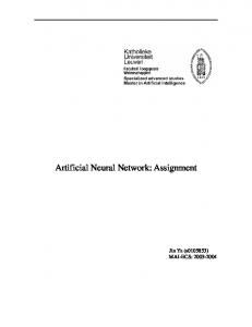
Collision-free assignment: If two neighboring cells use the same PCID, this is called a collision as shown in Figure 1a. Collisions can lead to situations where mobile terminals (MTs) in the common coverage area loose their connection or are not able to detect either one of the cells. This makes it almost impossible to detect collisions only based on radio measurement reports. Another problem is that MTs always select the strongest signal of a base station to compensate multipath propagation. If two cells are assigned identical PCIDs, it is impossible to distinguish whether the signals originate from the same or from different cells. It is possible that the stronger signal does not originate from the serving cell, which results in a connection drop.
•
Confusion-free assignment: Cells are called confused if two or more neighbors of a cell are assigned identical PCIDs as shown in figure 1b. Confusions impact especially handover handling. Cells store possible handover candidates in a table with the PCID as identifier for the respective cells. If an MT reports a certain PCID that is already part of the table, the base station assumes that this is a known cell. In case it is not a known cell but one with an identical PCID, a handover to this cell will fail. The identity based on the ECGI is not reassured, so the handover would be prepared with the wrong target cell. Confusion occurs when a new cell is introduced that connects two cells that have identical PCIDs but have previously not been neighbors. Or, the new cell is assigned a collision-free PCID which then causes the confusion for one of the neighboring cells.
B A
A
(a) Collision
A
A
(b) Confusion
Fig. 1: Collision and Confusion With conventional configuration schemes both problems can appear during initial setup and evolutionary growth of the network. For the initial setup the problem is less dangerous. The configuration of the inactive cells can be changed without causing outages. During evolutionary growth cells are added step by step to an operational network either at the borders of the coverage area to extend coverage or within covered areas to increase network capacity. When assigning a PCID to a new cell, the PCIDs of the neighboring cells must be taken into account. Often, new cells are confused or confuse already active cells. An appropriate assignment scheme is required to restrict service interruptions caused by PCID changes to a minimum. The already proposed configuration schemes as for example [5] cannot give guarantees that a valid configuration will be found. They are partly based on measurement results which can be incomplete. Even worse some of them start with only a single PCID assigned to all the cells, which are then stepwise changed. Changing the PCID of a single cell can cause numerous reconfigurations or even an infinite reconfiguration loop [6]. The basic approach solves both problems and at the same time minimizes the number of reconfigurations. It first transfers the neighborships of the network deployment into a graph consisting of nodes and undirected edges and then applies a generic graph coloring algorithm to compute the assignment. The graph is constructed as follows: • Each cell in the network is depicted as a node in the graph. • For any two neighboring cells an edge is added between the respective nodes in the graph. This satisfies the collision-free requirement.
For any two 2nd degree neighbors an edge is also added between the respective nodes. This satisfies the confusion-free requirement. By coloring the graph with the greedy algorithm by Welsh and Powell [7], it is assured that two neighboring nodes in the graph are never assigned the same color. The resulting colors are finally mapped to PCIDs, which results in a collision and confusion-free distribution of PCIDs. In addition to a fully autonomic PCID assignment, known properties of the algorithm are utilized. Operators e.g. obtain a first estimation whether an assignment is possible or not due to an insufficient number of available PCIDs [3]. For evolutionary network growth it does not make sense to apply a coloring algorithm and recolor the complete graph as this would lead to a high number of reconfigurations. Instead, the affected cells are restricted to an area just around the new cell. The following algorithm is used to color a new cell: • A node is added in the graph for the new cell. • Edges are added between that node and all nodes that represent neighboring cells of 1st and 2nd degree in the network. • A color is selected from those used by 3rd degree neighbors which has not been used by 1st or 2nd degree neighbors. • If all colors used by those 3rd degree neighbors are already used by 1st and 2nd degree neighbors, an appropriate color from any other node in the graph is reused. • If all colors in the graph are already used by the 1st and 2nd degree neighbors, a completely new color is assigned. • If all possible colors are already used by 1st and 2nd degree neighbors, a reassignment of the colors for the complete graph is tried. • After a successful assignment of a color, 1st degree neighbors are checked for multiple occurrences of the same color. If this is the case, recolor those neighboring cells to resolve the confusion. • Recoloring neighbors cannot cause additional confusions due to the distribution of colors enforced by the graph. Thus, additional checks are not required. This algorithm retains the properties of the basic algorithm by Welsh and Powell without reconsidering the complete graph. Evaluations have shown that this algorithm for evolutionary growth produces better results than the basic algorithm in terms of required PCIDs. •
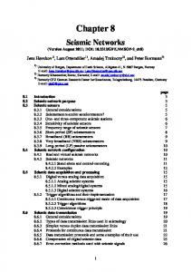
countermeasures to close the coverage gap [9]. An obvious method to close a coverage hole is to extend the coverage area of the surrounding cells. This results in new neighborships with a high risk of causing new collisions or confusions. Figure 2 shows a distribution of PCIDs which results from the basic approach. After coverage hole compensation one cell is confused that was not confused before.
1
3
4 5
1 2
(a) Neighborships before Coverage-Hole Treatment
1
2
3
5
1 2
Confused (b) Neighborships after Coverage-Hole Treatment
Fig. 2: Confusion after Cell Outage Compensation Requirements on PCID assignment not only differ between networks but also within a single operator network. The goal to satisfy all requirements with a single generic approach. The requirements should be specified on a high abstraction level and then be taken into account by the approach automatically. This is especially important if the differences not only originate from operators’ concepts but also from the context of the cells. Contextual influences could be location, cell type, or configuration of the neighboring cells. The two essential factors that influence the assignment algorithm are the construction of the graph and the selection of PCIDs for the nodes in the graph. Modifications of those factors can change the distribution of PCIDs to satisfy operator requirements and optimize the PCID assignment. •
III. O PTIMIZED A SSIGNMENT A PPROACHES The basic approach introduced in section II satisfies basic requirements for PCID assignment, but operators often have additional requirements. Some important ones are discussed in this section and it is shown how the basic approach is adapted to satisfy those additional requirements. One example that introduces additional requirements is the goal to reduce reconfigurations in case of a cell outage. Multiple reasons can lead to an outage of cell and mostly an outage results in a coverage loss in a certain area. Research[8] is targeted to first detect such an outage and then find appropriate
2
•
Changes of the graph: The graph constructed in the basic approach leads to a collision and confusion-free PCID assignment. Edges between nodes in the graph have an instantaneous impact on the assignment of PCIDs. Additional edges between nodes are used to enforce those nodes not to have the same PCID, e.g. to compensate for overshooting cells. Edges can also be removed for cells that are located closely to each other but will never interfere, e.g. when a cell is located within a subway tunnel. Changes of PCID selection: When a PCID is assigned to a node, the approach usually has the possibility to select one out of several possible PCIDs. Different selection strategies can be applied to enforce a PCID distribution according to operator requirements, e.g. to enforce a high reuse rate or to enforce an even distribution of PCIDs.
The following subsections introduce optimizations that can be reached by applying the presented changes of the basic approach.
A. Safety Margin Especially in urban areas with a large number of small cells a high reuse rate of PCIDs can be problematic. In addition to problems caused by coverage hole compensation, the conditions for radio wave propagation can change easily e.g. when buildings are changed or due to the change from summer to winter. In such situations previously non neighboring cells can become neighbors without configuration changes in the network. Such collisions or confusions have a negative impact on the service quality until they are detected and resolved. Safety margins are a preventive mean against such confusions. Cells are then configured with PCIDs that have not been used by 3rd or higher degree neighbors. A safety margin of three would have prevented the confusion in figure 2. A generic definition of the safety margin is: Definition 2 (Safety margin). A safety margin of n with regard to a parameter means that for any cell in the network the value of that parameter must not be reused by n-th degree neighbors and neighbors of lower degree. A safety margin of 1 means that a parameter may not have the same value as the same parameter at the direct neighbors. With a safety margin of 1, cells are assigned collision free PCIDs. With a safety margin of 2, the assignment is collision and confusion-free. For PCIDs this is equivalent to the basic approach. Safety margins also have a direct impact on the graph that is constructed for PCID assignment. In the basic approach the graph contains edges from each cell to its 1st and 2nd degree neighboring cells. PCIDs are reused for cells that are not connected by an edge in the graph. For a higher safety margins additional edges are introduced into the graph. For a safety margin of 5, edges from each cell to its 3rd, 4th, and 5th degree neighboring cells are added. The introduction of safety margins also requires an additional step during the incremental growth of the network. Inserting a cell might result in a violation of the safety margin of other cells. This is the case if the degree of a neighborship is decreased due to the insertion of a new cell. Therefore, the PCIDs of all neighboring cells of the new cell up to the degree of the safety margin have to checked. If duplicate PCIDs are detected among those neighbors, each of the affected cells is evaluated with respect to a possible safety margin violations. In case of a violation a new PCID is assigned to such a cell.
1
4
3 2
1
New Cell Fig. 3: Safety Margin Violation after Cell Insertion Figure 3 shows such a situation. All cells have a safety margin of four and a valid distribution of PCIDs is assigned.
The two outer cells both have PCID 1. Now, a new cell is inserted and the neighborships result as illustrated. Now, the evaluation is triggered for duplicate PCIDs at all cells within the safety margin of the new cell, i.e. at all cells in the figure. As the two outer cells are now 4th degree neighbors and have the same PCID, their safety margin is violated and one of those two cells is assigned a new PCID. Safety margins reduce the number of possible PCID distributions and raise the question whether there is a sufficient number of PCIDs for all cells. Simulations have shown that the number of cells that must not have identical PCIDs increases quickly when the safety margin is increased for all cells. Simulations are based on both data from real world networks and also a collection of synthetic networks. Tables I to III show the simulation results for the cells in some of those networks. • Network A represents a 3G network around Berlin and Brandenburg, Germany, that contains 229 cells without blanket coverage. • Network B represents a synthetic network that contains 6000 cells with a randomly generated geolocation within a certain area. The sum of surfaces of those cells covers the surface of that area 3.22 times. • Network C represents a homogeneous network that contains 10267 cells and has the shape of a regular hexagon. Each cell has the shape of a hexagon itself and has six other hexagons as neighbors, except the border cells. Analysis focuses on how the average number of neighbors and the actual number of PCIDs changes with increasing safety margin for those networks. Due to the different structure of those networks simulation results differ from each other. The average number of direct neighbors of a cell is significant for the average number of neighbors of higher degrees. A cell in network A has 3.6 direct neighbors in average whereas in network B a cell has 12.5 direct neighbors in average and 5.9 direct neighbors in network C. For this reason, the number of neighbors in the graph increases the lowest in network A and the fastest in network B. Another reason for this is the different structure of the networks. The 229 cells of network A are partitioned in 23 cell clusters that are not connected to each other, which results in an average cluster size of 10.0 cells. Due to the clustered structure and the relatively small cluster size an increasing safety margin has no significant effect on the number of neighbors of those cells which reside near the border of a cluster. As a result, the average number of neighbors increases almost constantly with an increasing safety margin. In contrast, networks B and C are not clustered at all, so their cells represent one large cluster. The border of the cluster is far enough away for most cells, so an increasing safety margin lets the average number of neighbors increase much faster than in network A. For a homogeneous network represented by a graph where each node has an equal number n of direct neighbors and that does not have any borders, the number of neighbors N with respect to a certain safety margin s is shown by equation (1).
Safety margin Degree of graph Avg. neighbors PCIDs
1 14 3.6 8
2 24 8.3 15
3 27 11.6 20
4 31 14.2 24
5 36 16.5 26
6 38 18.5 27
7 42 20.2 28
8 49 21.8 33
9 58 23.4 34
10 64 24.9 36
11 66 26.4 37
12 69 28.0 38
8 620 451.1 240
9 779 558.8 290
10 965 676.4 333
11 1173 802.4 381
12 1378 936.5 444
8 217 203.2 114
9 271 251.7 136
10 331 305.0 166
11 397 362.8 199
12 469 425.1 229
TABLE I: Network A (Real World) Safety margin Degree of graph Avg. neighbors PCIDs
1 27 12.5 14
2 66 37.5 30
3 116 75.2 51
4 187 126.2 76
5 272 189.9 114
6 373 265.7 149
7 489 353.1 189
TABLE II: Network B (Random) Safety margin Degree of graph Avg. neighbors PCIDs
1 6 5.9 7
2 19 18.7 14
3 37 36.1 23
4 61 59.0 36
5 91 87.3 51
6 127 120.8 69
7 169 159.5 89
TABLE III: Network C (Hexagon) 1500
80
1200
60
900 40
600 20
300
0 1
2
3
Degree of graph
4
5
6
7
8
Avg number of neighbors
9
10
11
12
Safety Margin
0 1
2
3
4
Degree of graph
Actual number of PCIDs
5
6
7
8
Avg number of neighbors
9
10
11
12
Safety Margin
Actual number of PCIDs
Fig. 5: Network B (Random)
Fig. 4: Network A (Real World) 500
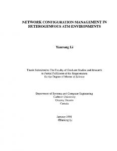
Network B and especially network C come pretty close to that structure, for which reason the equation approximates the average number of neighbors pretty good for those networks.
400
300
s · (s + 1) N (n, s) = n · (1) 2 The increasing number of direct neighbors in the graph leads to a higher consumption of PCIDs as illustrated in Figures 4 to 6. In the assignment process the PCID of a cell may not be reused for any neighbor in the graph in order not to violate the safety margin of that cell, so all neighbor cells must be assigned other PCIDs. However, two neighbor cells may be assigned the same PCID if they are far away from each other so their safety margin is not violated. For this reason one can observe with all networks that with an increasing safety margin the total number of assigned PCIDs also increases, but increases slower than the degree of the graph. The degree of the graph is the maximum number of neighbors at a node in the graph. One can also observe that in network A the actual number of assigned PCIDs is higher than the average number of neighbors in the graph whereas in networks B and C the actual number of assigned PCIDs is lower than the average
200
100
0 1
2
3
4
Degree of graph
5
6
7
8
Avg number of neighbors
9
10
11
12
Safety Margin
Actual number of PCIDs
Fig. 6: Network C (Hexagon)
number of neighbors in the graph. Again, the reason is the different structures of the networks. In a small cluster with a diameter close to the safety margin, PCIDs can hardly be reused. Thus, most cells are assigned different PCIDs and the number of PCIDs exceeds the average number of neighbors in such clusters, which leads to a high consumption of PCIDs in network A. In contrast, the huge cluster in networks B and C allows for assigning same PCIDs to multiple cells within
the safety margin of a cell as long as those neighbors are sufficiently far away from each other. Simulations also answered the question whether there are enough PCIDs to be assigned to the cells at all. In network A PCID assignment is no problem regardless of the safety margin as the total number of cells does not reach the total number of available PCIDs. For networks B and C, practical safety margins up to five are not a problem, assumed all 504 PCIDs are available, which is denoted in the respective diagrams by the red line. Simulations were performed up to a safety margin of twelve and still the algorithm finds a valid distribution of PCIDs. In case the number of PCIDs is insufficient for a valid assignment, the operator either has to change the deployment of the cells or to reduce the safety margin. The proposed possibility is to adapt the safety margin to the actual needs. Instead of having a fixed safety margin for all cells, the safety margin is dynamically chosen to fit the cell context. Cells in urban regions with a high cell density e.g. use a higher safety margin compared to sparsely distributed large cells in rural areas. Especially for the evolutionary growth of a network, location and coverage area of a cell are automatically considered to deduce an appropriate safety margin. Although this possibility seems simple at a first glance, it introduces difficulties in border areas between regions which require a high and regions with a lower safety margin. A cell is generally assigned a PCID with respect to the safety margin of the region where it is located. But in case a new rural cell is neighbor of an urban cell, the safety margin of the latter cell might be violated by other rural cells. Figure 7 shows such a situation in the border area of the rural and urban part of a network. The rural part has a safety margin of two, the urban part of five. A new cell is inserted into the rural area. Thus a safety margin of two applies. For the new cell PCID one seems to be a perfect match as none of the surrounding cells within its safety margin have that PCID. However, the safety margin of the urban cell with PCID one is violated.
1
2 1
5 4 Rural
1
3
New Cell
6 Urban
Fig. 7: Problematic Cell between Rural and Urban Areas Different safety margins for different regions also introduce additional complexity. In order to solve the described issue, additional constraints must be introduced for the border regions. For this purpose, two methods are available: •
Change of the safety margin: If one of the neighboring nodes in the graph has a higher safety margin, that safety margin is applied for the new cell. A disadvantage of this
method is that a larger number of cells in the rural area that are taken into consideration when assigning a PCID for the new cell. This causes an unnecessary reduction of possible PCIDs. Thus, a larger number of PCIDs are excluded from the set of PCID candidates for the new cell. • Additional violation checks: As soon as a neighborship to an area with higher safety margin is detected, all neighboring cells are evaluated up to the degree of that higher safety margin. If neighbors are detected whose safety margin is violated, those cells are reconfigured and assigned a new PCID with respect to their safety margin. However, one issue is not resolved by both methods. If the new cell has no direct neighborship to the urban region but is within the scope of the safety margin of an urban cell, the described additional evaluations will not be triggered and therefore the violation of the safety margin will not be detected. Operators could trigger the evaluation with the highest safety margin each time a new cell is introduced, but this would introduce a large overhead to the approach. A similar issue can appear when a very large cell is introduced in the border area. Due to its size such a cell has a very high number of neighboring cells. In this case a large number of rural cells are taken into consideration when assigning a PCID, but no additional benefit is gained. As the possibility of a collision or confusion is almost negligible due to the different radio environment, the high safety margin would put to many restrictions on the set of usable PCIDs and cause unnecessary reconfigurations. B. ID Space Partitioning and ID Selection The proposed solution is to apply PCIDs from disjoint PCID ranges for cells with different safety margins, which resolves the described issues instantaneously. Even more reasons make the partitioning of the PCID space an appealing approach. Operators can choose to assign PCIDs from different sets for different cell types, for example Macro, Pico, Micro, or Femto. They may use only certain PCIDs for certain subnets such as regional or vendor-specific ones. Especially in regions where several networks operate in the same frequency band for example due to borders between countries or between license areas, a single operator cannot influence the PCID assignment to all cells. The solution to this issue is to agree with the other operators to use disjoint PCID sets in this area. Apart from organizational reasons the PCID space could also be partitioned due to physical properties of the PCIDs. There are combinations of PCIDs which show a very high resistance against radio interference from neighboring cells. Other PCIDs allow a fast detection of neighboring cells due to their physical properties. However, the danger of PCID exhaustion increases along with the number of PCID sets, so there might be situations where a particular ID set is exhausted while another still has a lot of PCIDs available. In this case the operator might shift some PCIDs from one set to another one or to reconfigure the network layout. In extreme cases a PCID distribution with
partitioned PCID subsets might not be possible at all, whereas a PCID distribution would exist without disjoint PCID sets. Instead of defining fixed PCID sets, the proposed solution is to describe those sets in a flexible way via high-level policies. Those policies specify the properties of the PCIDs to be selected and the maximal number of PCIDs for a particular set. This solution will not resolve the issue completely, but relaxes the need for a specific pre-assessment of the required PCIDs and reduces the danger of PCID exhaustion due to an improper partitioning of the PCID space. After the definition of those policies the PCID sets are empty. Each time a new PCID is required, an appropriate one is selected from the overall PCID space and places it into the respective set. In case the policy defines combinations of PCIDs which satisfy a set of requirements such as all PCIDs that are constructed from a set of identity groups, not only a single PCID but a whole group that satisfies the requirement is shifted to the set. In case no PCIDs are available that satisfy the requirements, alternative selection procedures have to be applied or the given configuration has to be changed. Apart from partitioning the ID space, selection of the PCIDs from a given set is an important mean to influence the PCID distribution in the network. The basic approach enforces a very high reuse rate by assigning each cell a PCID that has been used by a 3rd degree neighbor if possible. If there is no such PCID available, the approach dictates to evaluate the PCIDs used in the complete network to find one that has not been used by 1st or 2nd degree neighbors. In case of a safety margin, a higher degree of safety margin plus one is chosen for the reuse of a PCID. Only if there is no such PCID, a new one is chosen from the ones provided for the network. Two changes to the selection process have major impact on the distribution of the PCIDs: • Selection of unused PCIDs: Instead of forcing the reuse of PCIDs, those that have not yet been assigned at all are selected. At the beginning of the assignment collisions, confusions, and violations of safety margins are impossible, but as soon as all PCIDs have been used they can possibly occur again. From this point, a reuse rate is enforced that is implicitly dictated by the safety margin. • Assignment frequency: Additional thoughts can be spent on the distribution frequency of the PCIDs. An operator could for example specify the requirement of an even distribution of PCIDs with a maximal reuse rate. Another possibility is that cells with a large number of neighbors should have identical PCIDs. Such requirements lead to a further partitioning of the PCID space. However, this is a soft partitioning as it always selects from the same PCID set, but tries to satisfy those additional requirements. IV. A PPLICATION TO OTHER R ADIO PARAMETERS Deploying a large number of different algorithms and autonomic subsystems decreases the maintainability of a system. Especially in already complex setups this complicates not only debugging but also optimization of the algorithms. Therefore,
it is important to evaluate established and well understood parts of the system with regard to the applicability to the configuration of other radio parameters. The basic approach together with the extensions of safety margins and the possibility to influence the selection process is a versatile tool that should be usable for all configurations that have to deal with interrelated parameters. This applies to interrelation of different parameters within a single cell as well as to parameters of different cells. The questions to answer are which parameters can be handled that way and which adaptations have to be applied to the graph and the selection process. In LTE networks a large number of parameters have to be configured. 3GPP[10] proposes a number of categories for the classification of parameters. Those categories have been adapted to fit more types of interdependencies. 1. Parameters need to be configured identically within the complete network, a subnetwork, or a certain area within the network. The graph for these parameters is a full mesh and the selection policy is to assign identical values to all nodes connected by edges. For this category graph coloring does not provide additional benefit, but it can be used to retrieve a configuration. 2. Parameters have to be configured differently on all occurrences within a network, a subnetwork or a certain area within the network. This corresponds to a collision-free assignment with varying safety margins. This scenario can be seen as the inverse of category 1 if all occurrences of a parameter in the network have to be considered. The selection policy is to assign different values to all nodes connected by edges. 3. Configuration of a parameter needs to be aligned with the configuration of the same parameter on other nodes (e.g. 1st, 2nd, 3rd degree neighbors), which extends category 2. The alignment is not a pure exclusion of possible parameter values but can also specify differentiated selection policies. For example, the average value of the parameters could be used that are assigned at the neighboring cells. 4. Parameter configuration needs to be aligned with some other parameters. 5. Any combinations of the categories. For every category a graph that expresses the dependencies between the parameters is constructed. Some of the problems in the categories can be treated with a single graph, for others multiple graphs are needed. Depending on the specification of the concrete problem, a single graph can be sufficient for category 2 problems to exclude some configurations, or a second graph is needed that specifies possible configurations. The PCID assignment problem falls into this category. If several parameters need to be aligned, multiple graphs are combined with an appropriate selection process. This is the case if e.g. a parameter has to be configured collision-free but also depends on the configurations of another parameter at other cells. The graphs are then used to determine possible configurations. In the second step all configurations that collide
with neighbors are removed. In a last step the selection process assigns a configuration. A selection of LTE radio network parameters has been categorized below. If the acronyms are not referenced differently, they are explained in [11]. Category 1: • Public Land Mobile Network ID • Number of Physical Resource Block Category 2: • Site ID - Unique for the complete Network • EUTRAN Cell Global ID - Globally Unique Category 3: • PRACH Root Sequence ID: Although multiple sequences are required, only the index of the first PRACH root sequence is configured for a cell. Any of the consecutively assigned root sequences to a cell must be collisionfree towards the neighboring cells. The number of required root sequences per cell is determined dynamically on a per cell basis. To solve the task a simple graph with a safety margin of one is used. All nodes are assigned multiple consecutive colors. The selection process has to find a set of consecutive colors that is sufficiently large to satisfy the requirements for the new cell. To reach an initial configuration that is already optimized from the beginning, the required number of PRACH root sequences is computed and then the nodes are sorted in decreasing order by degree of the node and number of required sequences. The assignment process starts at the node with the most neighbors and the largest number of required sequences. No reuse will be applied until all of the root sequences have been assigned once. This helps to avoid gaps in the sequence space. The selection process tries to avoid such gaps when reusing the sequence space. • Cell-Specific Reference Signal Cyclic Shift: This is an important parameter which is needed to increase the number of mobile terminals that can be multiplexed within a single cell. The cell-specific cyclic shift has to be defined collision-free to avoid service interruptions for the mobile terminals in the common coverage area of neighboring cells. As a solution to the task a graph with safety margin one is used. • Frequency Band: For LTE networks several frequency bands are specified. Single operators can have multiple frequency bands which are then assigned to the cells to gain a maximal capacity. For the solution of the task, two graphs are generated, one with cells which are configured to an identical frequency band and one from a cell to all cells that are configured to a different frequency band. The selection process has to select the correct frequency band for a given cell in accordance to the cells that need to be configured similar. Category 4: • Tracking Area Code (TAC): The TAC is part of the Tracking Area Identity. In the graph the new node is connected to the geographical neighbors and in a first step
selects the TAC that the majority of the neighbors use. An optimization process may change the TAC configuration at a later point in time. V. C ONCLUSION A successful extension of the basic graph coloring based Physical Cell ID assignment approach was presented. Requirements of mobile network operators were satisfied with the application of just two extensions, the introduction of safety margins and the possibility to influence PCID selection. Safety margins raise the level of resilience against issues that arise through unplanned neighborships after a successful compensation of a cell outtage. The combination of a preassessment of failures and additional safety margins for parameter assignment can strongly increase the operational reliability of a mobile network. The ability to influence the PCID selection process offers operators to partition the PCID space and to coordinate the assignment while still retaining parameter assignment collision- and confusion-free. Partitioned PCID spaces facilitate the circumvention of collisions and confusions between different subnetwork types or in border regions where the operator cannot influence the PCID assignment of neighboring networks that operate in the same frequency band. The analysis of the potential application of the graph based approach to further parameters has shown that it is possible to use the same basic approach with only minor changes in the underlying graph and the selection process. The ability to configure different parameters with basically the same configuration scheme increases the reliability of the autonomic functions and reduces the necessity for different algorithms and approaches. It is important to keep the number of deployed approaches at a low level in order to achieve a high level of manageability, controllability, and responsiveness of a system. R EFERENCES [1] Hamid Akhavan et al., “Next Generation Mobile Networks - Beyond HSPA & EVDO - Whitepaper,” Tech. Rep., NGMN Ltd. www.ngmn.org, 2006. [2] Harri Holma and Antti Toskala, WCDMA for UMTS: HSPA Evolution and LTE, John Wiley & Sons, Inc., New York, NY, USA, 2007. [3] Tobias Bandh, Henning Sanneck, and Georg Carle, “Graph coloring based physical cell id assignment for lte networks,” in IWCMC2009. [4] 3GPP, “3GPP TS 36.300,” Technical Specification Release 8, 3GPP, 09 2008. [5] M. et al. Amirijoo, “Neighbor cell relation list and measured cell identity management in lte,” Network Operations and Management Symposium, 2008. NOMS 2008. IEEE, pp. 152–159, April 2008. [6] 3GPP, “3GPP S5-081185,” TDOC Automatic Physical Cell ID Assignment, 3GPP, 07 2008. [7] D. J. A. Welsh and M. B. Powell, “An upper bound for the chromatic number of a graph and its application to timetabling problems,” The Computer Journal, vol. 10, no. 1, pp. 85–86, 1967. [8] “Socrates - FP7 - http://www.fp7-socrates.org,” 02.12.2008. [9] M. Amirijoo, L. Jorguseski, T. K¨urner, M. Neuland R. Litjens, L. C. Schmelz, and U. T¨urke, “Cell outage management in lte networks,” in ISWCS, 2009. [10] 3GPP, “3GPP S5-092289,” Tech. Rep. Parameters Subject to Dynamic Radio Configuration, 3GPP, 05 2009. [11] LTE - The UMTS Long Term Evolution - A Pocket Dictionary of Acronyms, Wiley, 2009.