3rd WSEAS International Conference on APPLIED and THEORETICAL MECHANICS, Spain, December 14-16, 2007
168
Optimized Quenched Layer for Receiving Optimal Residual Stress Distribution and Superstrengthened Material NIKOLAI KOBASKO Intensive Technologies Ltd, Kyiv, UKRAINE
[email protected] ,
[email protected] Abstract:- The main idea of this paper consists in creation of the optimal depth of shell which provides optimal stress distribution in quenched steel parts. For small steel parts optimal quenched layer can be provided by using of low and limited hardenability steels (LH). For big steel parts optimal quenched layer can be provided by use of low alloy steels. Since the LH steel core does not harden significantly, the ductility of the core is also maintained. The same is true when using low alloy steels for manufacturing big steel parts. The grain sizes of LH steels are above ASTM 8. It is shown that the high level of compressive surface residual stresses and steel superstrengthening phenomenon can eliminate the need for secondary shot peening or surface induction operations. Also carburized alloy steels can be successfully replaced by LH steels to increase service life and decrease cost of materials. Key- Words:- Optimized quenched layer, High compressive residual stresses, Superstrengthened material, Service life.
1 Introduction Heat treatment of metals is a branch of science the purpose of which is the creation of high-strength materials [1-7]. It has been recommended to quench alloy and high-alloy steels in oils or aqueous polymer solutions of high concentration, and plain carbon steels in water. Oils are used to reduce quench cracking and distortion of parts while they are hardened through. For this reason, slow cooling is used and expensive alloy elements are applied for providing through-hardening. So, oil quenching is performed at not big temperature gradients on cross sections of parts, and their through-hardening is reached due to alloying. It was widely accepted that alloy steels should be quenched very slowly within the martensite range and this was a basic rule, which was stated in all manuals and handbooks on heat treatment of materials. It was developed a new approach which allows intensive quenching alloy and high alloy steels in plain water [5, 6]. The paper suggests a new approach in the technology of quenching alloy and high-alloy, and limited – hardenability steels on the basis of investigations ideal critical diameters DI [8]. It lies in the following: • •
Very intensive quenching is performed during all the period of part’s quenching, including martensite range. Intensive quenching results in the creation of high compressive stresses at the surface of parts.
•
•
• •
Intensive quenching in the martensite range creates high dislocation density in the material, which results in improvement of the material strength. The creation of high dislocation density and high compressive stresses at the surface layers of parts quenched increases their service life. To have these results optimal quenched layer should be achieved after intensive quenching. Optimal quenched layer for limited – hardenability steels can be provided by knowing critical diameter DI.
Intensive quenching gives the following benefits: • •
• • • • •
Using less expensive materials instead of alloy and high-alloy steel grades; Increasing the hardness of the surface quenched by HRC 2 – 5, which in some cases allows to avoid carburizing of surface layers or reduce the time of carburizing; Minimizing distortion of parts quenched and optimizing compressive residual stresses at the surface; Maximizing labor productivity; Reducing the number of manufacturing operations; Replacing expensive and fire-dangerous oils by plain water; Improving ecological conditions of environment.
3rd WSEAS International Conference on APPLIED and THEORETICAL MECHANICS, Spain, December 14-16, 2007
With regard to the above-mentioned advantages, let’s consider in detail factors having effect upon the strength and service life of steel parts on the basis of critical diameters DI [8].
2 Critical diameter and critical size for any configuration of steel part Let there is a body of any shape with a surface area of S and volume of V , which is cooled in the quenchant at constant temperature Tm from initial temperature T0 . Cooling occurs by the law of Newton, i.e., at boundary conditions of the third kind (see Fig. 1). It is required to study relative regularities at the stage of regular thermal process.
Fig. 1 A gear cooled in the quenchant with constant temperature Tm by the law of Newton It has been proved [2] that the general solution of such a problem for bodies of any shape can be presented as follows: ∞ T − Tm = ∑ AnU n exp(− mnτ ), T0 − Tm n =1
(1)
An are temperature amplitudes; U n are eigenfunction dependent on coordinates. For most cases at the core of steel parts U n = 1; m1 < m2 < m3 ...mn < mm+1 …
(2)
In view of inequalities (2) in a short time the process of cooling of a body of any shape will be described by just plain exponent.
θ = A1U 1e − m τ . 1
For ideal quenching when Bi > 50
(3)
θ = A1U 1e
− Ka τ
.
169
(4)
Here m1 = a /K; a is thermal diffusivity of a material (m2/s); K is Kondratjev form factor (m2). Cooling process of any steel part in regular condition at the core can be described by Eq. (3). For example, for cylinder K =R2/5.783; for ball K = R2 / 9.87 and so on. Here R is radius of cylinder and ball. For many steel parts analytical values of K are shown in the Table 1. For steel part of any shape and size cooling time t in regular condition can be calculated by Eq. (3). To prove this idea some experiments are presented on Fig. 2 showing that at the core of gear regular condition take place and Eq. (3) can be used.
Fig. 2 Temperature versus time in different areas of gear plotted in semi logarithm scale: in areas of gear 4 – 8 the process of cooling is described by plain exponent (3) [1]. On the basis of Kondratjev theory of regular condition it was received an equation (5) for evaluating ideal critical diameter DI which is as follows:
abτ M DI = Ω + ln θ
0.5
.
(5)
The limit time of the core cooling τ M is determined from the CCT diagram and evaluated as the point of crossing the Ms line with the curve corresponding to 50% martensite formation. On the other hand, there is correlation between DI and chemical composition of steel (Grossmann 1942, Field 1943) presented in the form [9]: DI = 25.4fCfMn fSi fCr fMo fV fCu ,
(6)
where fx is the multiplying factor for the particular alloying element.
3rd WSEAS International Conference on APPLIED and THEORETICAL MECHANICS, Spain, December 14-16, 2007
If we know DI and size of steel part we can evaluate suitable chemical composition of steel to provide optimal stress distribution in the body [8]. Special Software has been designed for such calculations to achieve optimal residual stress distribution. Table 1 Kondratjev form factor K and parameter p for bodies of a simple configuration Shape of the p K, m2 part Unbounded 2.34 L2 plate of π2 thickness L Infinite 1 R2 cylinder of 5.784 radius R 1.17 Square infinite L2 prism with 2π 2 equal sides of L 1.48 R2 Finite cylinder, R=Z 15 ⋅ 65 Finite cylinder 2R=Z Cube with side of L Ball
R2 8.252 L2 3π 2 R2
0.70 0.78 0.586
π2
Table 2 Kondratjev form factors K and parameter p for bodies of a complex configuration (results of numerical calculations)
Form of steel parts
K, m2
80⋅10-6
73.⋅10-6
p
1.42
2.9
To go from cylindrical critical diameter to critical size of any form of steel part we should
170
know the value p, which can be evaluated from the ratio:
p=
Ka , K
(7)
where Ka is Kondratjev form factor for any steel parts; K is Kondratjev form factor for cylinder. For example, for ball K = R2 / 9.87; for cylinder K = R2 / 5.783. It means that p = 5.783/9.87 = 0.59. The critical size of any configuration is evaluated then from the equation (8):
DI a =
DI p
(8)
3 Optimized – Quench Processes for Low and Limited – Hardenability Steels To provide optimal residual stress distribution during intensive quenching the ratio DIa / Dopt should be within 0.2…0.8, where DIa is critical size of any configuration of steel part; Dopt is specific size of real steel part. When steel part is quenched through, the ratio DIa / Dopt = 1, when ratio DIa / Dopt = 0, the martensite layer is about zero. For each configuration of steel part there is optimal quenched layer which provides optimal stress distribution, i.e.: very high compressive residual stresses at the surface and not big residual tensile stresses at the core. In this case gradual transition from compressive residual stress to tensile one is observed. It should be noted that for the fixed configuration the ratio remains the same with the changing size of steel part. It means that for the fixed configuration the next equation is true:
DI a = const. (9) Dopt The optimal stress distribution during quenching can be find using 2D or 3D Software [10 - 13]. We used software TANDEM [10], which was developed by us for solving two-dimensional problems of heat conduction and stress-strain state of steels during quenching. The thermal and stress-strain state is computed on the basis of finite-element method [14]. The mathematical model, on which the program is based, includes the non-linear equation of non-stationary heat conductivity and equations of the theory of elastic – plastic flows with cinematic strengthening under the relevant boundary conditions [4 - 10]. The calculation results are:
3rd WSEAS International Conference on APPLIED and THEORETICAL MECHANICS, Spain, December 14-16, 2007
temperature field, phase distribution, disposition of points in the volume computed, stress and strain fields, intensities of stress and strain, and the field of the safety factor, that is, a relation of stresses at which the material is destroyed. These values are presented in the form of tables and isometric lines that allow to observe the kinetics of phase changes in the process of heating and cooling Table 3 Chemical Composition of Some Limited- Hardenability Steels Steel C Si Mn Cr 58 0.56 0.30 0.09 0.10 (58PP) GOST 1050-74 ShKh4, 0.95- 0.15- 0.15- 0.35GOST 1.05 0.30 0.30 0.50 801- 78
Certified Al 0.08
0.0150.05
Let us calculate critical diameters for the 58(55PP) and ShKh4 steels using equation (6) and Tables 3 and 4 [15]. The first steel 58(55PP) has the critical diameter as follows: DI = 25.4DIbasefMn fSi fCr fNi = 25.4 x 0.23 x 1.21 x 1.3 x 1.22 x 1.015 = 11.4 mm. The critical diameter of investigated gear is DIa = DI/p = 11.4/2.9 = 3.93 mm, or approximately 4 mm. Then the ratio (9) is equal approximately to 0.2, because DIa / DI opt = 3.93 mm/ 24.14 mm = 0.16. For gear this ratio is approximately 0.2. The small ratio is explained by thin teeth of gear. Such small ratio provides shell of optimal thickness around the all teeth. The same approach is true for stamped rings shown in Table 2.Assume that ring in the second line is made of the same steel having critical diameter DI = 11.4 mm, evaluated from the equation (6). Then the ratio (9) is equal approximately to 0.22, because DIa = 11.4 mm; p = 1.42 and DIa / DI opt = 0.22. Assume that die having form of finite cylinder (50 mm in diameter and 50 mm in height) is made of ShKh4 steel. Then : DI = 25.4DIbasefMn fSi fCr fNi = = 25.4 x 0.323 x 1.5 x 1.14 x 1.75 x 1.1 = 27 mm. For mentioned die the value p = 0.7 (see Table 1), that is why DIa = 27mm/0.7 =38.6 mm. The ratio DIa / DI opt = 0.77 or approximately 0.8. Thus the ratio DIa / DI opt can be within 0.2 …0.8. The optimal phase and stresses distribution after intensive quenching for 20 s is presented in Fig. 4. A forging made of AISI 52100 steel was intensively quenched in condition of α=20,000 W/m2K during 20 seconds and then immediately tempered . Interruption of the process of intensive cooling was needed to create optimal quenched layer as is shown in Fig.4 .Due to optimal hard layer and soft core, very high compressive stresses at the surface appeared. The
171
same effect can be provided by use of LH steel ShKh2. The chemical composition of this steel is as follows: 1.15 – 1.25 C; 0.15- 0.30 Si; 0.15 – 0.30 Mn; 0.015 – 0.030 Al; < 0.15 Cr; < 0.10 Ni; < 0.12 Cu; and < 0.03% Mo. According to Eq. (6) and Table 4 we have: fC = 0.35; fSi = 1.2; fMn = 2; fCr = 1.3; fNi = 1.03; fMo = 1.05; or DI = 30 mm. According to Table 2, DIa = 30 mm/ 1.42 = 21 mm. Finally we are getting DIa /Dopt = 21mm/ 36mm = 0.58 for the maximum content of alloy elements in ShKh2 steel. For the average content of alloy elements we have: fC = 0.32; fSi = 1.14; fMn = 1.67; fCr = 1.15; fNi = 1.018; fMo = 1.06; or DI = 19.2 mm. After similar calculation we have DIa / Dopt = 0.37. It means that phase distribution after intensive quenching of forging made of ShKh2 steel will be similar to phase distribution as shown in Fig. 5. There is sense to make this parts using less expensive steel ShKh2. Optimal intensively quenched layer provides high residual compressive stresses at the surface. The service life of steel parts made of ShKh2 steel will be higher due to compressive residual stresses at the surface and superstrengthened material in the intensively quenched layer.
Fig. 3 Phase distribution at 20 s for forging when α=20,000 W/m2K (1 is intermediate phase, 5 is martensite).
3rd WSEAS International Conference on APPLIED and THEORETICAL MECHANICS, Spain, December 14-16, 2007
4 5 6 7 8 9 A B C D E F G H I J
-1360 -1320 -1280 -1240 -1200 -1160 -1120 -1080 -1040 -1000 -960 -920 -880 -840 -800 -760
-
-1340 -1300 -1260 -1220 -1180 -1140 -1100 -1060 -1020 -980 -940 -900 -860 -820 -780 -740
K L M O P Q R ˆ ‰ ‹ “ ” – — ˜ ™
-720 -680 -640 -560 -520 -480 -440 120 160 200 280 320 360 400 440 480
-
-700 -660 -620 -540 -500 -460 -420 140 180 220 300 340 380 420 460 500
4 Applications of IQ Processes on the Basis of Limited- Hardenability Steels It has been shown by investigations of authors [4, 16, and 17] that LH steels have a great future. They developed steels: 58 (55PP), 45C, 47GT, ShKh4 and others. These steels contain small amounts of aluminum, titanium, and vanadium. They are less expensive than conventional alloy grades because they use two to three times less total alloying elements. Simultaneously the service life of machine parts made of LH steels increases two to three times when properly intensively quenched.
Fig. 5 Quenching device [4, 16, 17]: 1 - changeable mandrel; 2 – driving wheel to be quenched; 3 – cone; 4 – removing device; 5 – hydraulic cylinder for vertical movement and wheel fixing; 6 – receiver of parts; 7 – hydraulic cylinder for wheel feeding; 8 – inductor.
Table 4: Production Applications of IntensiveQuenched Limited- Hardenability Steels Applicati Former New Advantages on Steel and Steel and Process Process Gears, 18KhGT 58 No
172
Fig.4 Hoop stresses σ 33 (MPa) at 20 s when α=20,000 W/m2K
modulus m = 5-8 mm
Largemodulus gears, m = 10-14
(55PP)
12KhN3
ShKh4
carburizing, steel and part costs decrease; durability increases. No carburizing, durability increases 2 times, cost steel decreases 1.5 times.
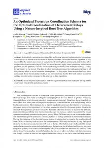
Production application of intensive – quenched LH steels for making gears is shown in Table 4. The gears were quenched in water flow using device shown in Fig. 6. All of these data were archived on the basis of pure experiments. It was no clear what it is optimal quenched layer and how intensively gears should be quenched to receive optimal residual stress distribution and superstrengthened material. A present work gives clear instruction what to do, how to do and how chemical composition of LH steels can be optimized. It become possible because patented technologies [5, 6] are very suitable for LH steels. As we can see from Fig. 6, intensively quenched LH steels create shell around the teeth and due to this very hard martensite shell very high compressive residual stresses are appearing at the surface of steel parts. Also due to very fast cooling rate within the martensite range additional strengthening (superstrengthening) of material is observed [16, 17]. This relatively new direction of use in the practice LH steels need more detailed and comprehensive investigation. As it was already shown, the benefits are very promising.
3rd WSEAS International Conference on APPLIED and THEORETICAL MECHANICS, Spain, December 14-16, 2007
173
use of low-alloy steels. In both cases, steels must be quenched extremely intensively by plain water.
Fig. 6 Macrostructure of driving wheels with module of 4 – 6 mm after through heating and intensive quenching: light zones are the hard layers having martensite structure and hardness greater than HRC 60; dark zones are areas with the structures of troostite or sorbite and hardness of HRC 30 – 45 [16, 17].
5 Conclusions 1. A method for designing optimal quenched layer, like gears, on the basis of use limited – hardenability steels is developed. The method allows obtaining optimal stress distribution through quenched steel part and providing additional strengthening of a material. 2. The method allows using plain carbon steels instead of expensive alloy steels. 3. The developed method is the first step in optimizing technological quenching processes. The second step is computer simulation to obtain exact value of the ratio DIa / Dopt and value of safe factor which allows preventing crack formation during quenching. 4. The limited – hardenability steels have a great future since the technological process is environmentally friendly, instead of oils plain water is used; service life of steel parts increases by 2-3 times; cost of material and part production decreases 1.5 times; the new technological process can eliminate completely expensive carburizing process which saves energy and decreases emission of CO2 into atmosphere. 5. Wide applying of limited-hardenability steels and new technological processes in industry can be fulfilled on the basis of designing and manufacturing new equipment for the intensive-quench technologies. 6. For quenching LH steels new patented technologies are used [5, 6]. 7. It is advisable for parts of low sizes to use low-hardenability steels providing the optimal depth of hardened layer. As for large-size parts, the optimal depth of hardened layer can be reached through the
References: [1] N.I.Kobasko, Steel Quenching in Liquid Media Under Pressure, Kyiv, Naukova Dumka, 1980, 206p. [2] G.M.Kondratjev, Thermal measurements, Moscow-Leningrad, Mashgiz, 1957, 244p [3] N.I.Kobasko, Steel Superstrengthening Phenomenon, Journal of ASTM, February 2005, Vol. 2, No 2, Paper ID JAI 12824, pp. 1-13, Available online at www.astm.org [4] N.I.Kobasko, W.S.Morhuniuk, B.K.Ushakov, Design of Steel- Intensive Quench Processes, Handbook of Metallurgical Process Design, G.E.Totten, Kiyoshi Funatani, Lin Xie (Eds), Marcel Dekker,Inc., New York, 2004, pp.733 – 764. [5] N.I.Kobasko, Ukraine Patent #56189 [6] N.I.Kobasko, US Patent # 6,364,974B1 [7] N.I. Kobasko, W.S. Morhuniuk, Study of Thermal and Stress-Strain State at Heat Treatment of Machine Parts, Znanie, Kyiv, 1983, 16 p [8] Nikolai Kobasko, Quench Process Optimization for Receiving Super Strong Materials, WSEAS TRANSACTIONS ON SYSTEMS, Issue 9, Vol. 4, Sept. 2005, pp.1394 – 1401. [9] M.A.Grossmann, AIME, February 1942 and J. Field, Material Progress, USA, March 1943. [10] N.I.Kobasko, W.S.Morhuniuk, V.V.Dobrivecher, Software “TandemHart Analysis”, commercially available from Intensive Technologies Ltd. Kyiv, Ukraine (e-mail:
[email protected], www.itl.kiev.ua) [11] Ferguson B. Lynn, Freborg Andrew, and Petrus Gregory J. Software Simulates Quenching Heat Treating Progress, August 2000, H31 - H36. [12] Inoue T, Arimoto K, Development and Implementation of CAE System "HEARTS" for Heat Treatment Simulation Based on Metallo - Thermo Mechanics. J. Mater. Eng. Perform. Vol. 6 (No.1), Feb. 1997, 51 - 60 p [13] Inoue T. Metallo - Thermo - Mechanics Application to Quenching in “Handbook of Residual Stress and Deformation of Steel” (G. Totten, M. Howes, T. Inoue (Eds)), Materials Park, OH 44073, ASM International, 499 p
3rd WSEAS International Conference on APPLIED and THEORETICAL MECHANICS, Spain, December 14-16, 2007
[14] O.C.Zienkiewiez, The Finite Element Method in Engineering Science, Moscow, Mir, 1975, 542 p. [15] Totten J.E., Bates C.E., Clinton N.A. Handbook of Quenchants and Quenching Technology, ASM International, 1993, 580 p [16] B.K.Ouchakov, K.Z.Shepeljakovsky, New Steels and Methods for Induction Hardening of Bearing Rings and Rollers, In a book Bearing Steels into the 21st
174
Century (Joseph J.C. Hoo Willard B. Green Ir., Eds); ASTM (American Society for Testing and Materials), 1998, p 307 – 320. [17] K.Z.Shepelyakovsky, B.K.Ushakov, Induction surface hardening- Progressive technology of XX and XXI Centuries, Proc. of the 7th int. Conference on Heat Treatment and Technology of Surface Coatings, Moscow, V. 2, 11-14 Dec. 1990, p p.33- 40