COMPDYN 2015 5th ECCOMAS Thematic Conference on Computational Methods in Structural Dynamics and Earthquake Engineering M. Papadrakakis, V. Papadopoulos, V. Plevris (eds.) Crete Island, Greece, 25–27 May 2015
OPTIMIZED RETROFIT OF SEISMICALLY DESIGNED STRUCTURES TO WITHSTAND PROGRESSIVE COLLAPSE Georgios S. Papavasileiou and Dimos C. Charmpis Department of Civil and Environmental Engineering, University of Cyprus, 75 Kallipoleos Str., P.O. Box 20537, 1678 Nicosia, Cyprus, E-mails:
[email protected],
[email protected]
Keywords: Progressive collapse, robustness, damage tolerance, local failure, alternate load path, column loss, seismic design, structural optimization, retrofit. Abstract. Seismically designed buildings possess the necessary properties to withstand the design earthquake excitations and limit structural damage to the desired level. This is achieved by appropriately defining individual member capacities, interstorey and global stiffnesses and energy dissipation mechanisms based on the provisions of current design codes. However, such provisions do not suffice, in order to protect a structure from disproportional extent of damage when a local failure occurs. Hence, in order to increase their progressive collapse resistance, existing seismically designed buildings need to be appropriately retrofitted. This paper presents an optimization procedure for the retrofit of seismically designed buildings, in order to increase their capacity to sustain local damage without extensive propagation leading to severe structural failure (partial/full collapse). Two retrofit methods for seismically designed steel-concrete composite buildings are presented and assessed with respect to their costeffectiveness. The retrofit methods are based on: (a) the strengthening of beams in the structure or (b) the installation of bracings in the horizontal direction. Structural optimization aims to minimize the total retrofit cost, in order to determine the lowest possible need for retrofit material, enabling at the same time the comparative assessment of the two retrofit methods on a ‘fair basis’.
3568
Georgios S. Papavasileiou and Dimos C. Charmpis
1
INTRODUCTION
Design against progressive collapse has been a concern for engineers since the Ronan Point collapse in London on May 16, 1968, as its results are disproportionate to the cause: small scale damage triggers extended damage or failure of a number of neighboring structural elements, which might result in collapse of a part –if not of the whole– of the building. However, intensive investigation of such phenomena, as well as of methods to reduce their effects, started only after the collapse of the World Trade Center towers in September 11, 2001. Design strategies to control the damage propagation or reduce the probability of occurrence of the initial failure have been proposed [1-8]. Up to now, due to the non-compulsory nature of the design strategies, a very limited number of existing buildings has been designed against progressive collapse. Hence, certain buildings may need to be retrofitted appropriately, in order to reduce the risk of progressive collapse, when they sustain small-scale damage. Thus a corresponding need to develop and examine retrofit methods arises. The preference of a retrofit method over another depends on the cost over effectiveness attained by each one, since the cost induced plays a key role in deciding for and realizing a retrofit solution. Even when progressive collapse resistance is taken into consideration in the design phase of a building, the additional cost to achieve such resistance is considerable. Over the last decades, structural design optimization has progressed to a valuable computational tool, which assists the engineer in making best use of structural material, in order to detect a feasible and cost-effective design satisfying certain pre-specified constraints. The present work presents an optimization procedure for the retrofit of composite steel-concrete buildings in order to resist earthquake actions and progressive collapse. The Evolution Strategies optimization algorithm is employed in order to minimize the total retrofit cost, subject to constraints on (a) the safety of structural members, (b) the structural system resistance against earthquake and (c) the building’s capacity to sustain failure of load-bearing elements without disproportionate propagation of the structural damage. Structural optimization approaches to achieve progressive collapse resistance in a cost-effective manner in the design phase of a building have been presented in [7,8]. Various retrofit methods for existing structural systems are provided in the literature (e.g. [9-14]). Two retrofit approaches for composite buildings are examined in this work: (a) strengthening of beams by welding additional elements (plates or members with I-shaped sections) at their lower flanges and (b) installation of additional bracings to form external horizontal trusses at predefined storeys. A numerical application involving the retrofit of a 6-storey composite steel-concrete building demonstrates the effectiveness of the proposed optimization approach and illustrates the comparative effectiveness of the two retrofit approaches. 2
THE ALTERNATE LOAD PATH METHOD
One of the measures proposed to reduce the potential for progressive collapse is the alternate load path method [2,5-8]. According to this method, the assessed structural design should be able to redistribute successfully the acting loads when local failure takes place, without extensive propagation of structural damage, which indicates the initiation of a chain reaction that might lead to collapse. Thus, alternate load paths, which utilize undamaged members to transfer the loads to the ground, need to be available after the initial failure occurs. The alternate load path method is implemented by artificially removing certain structural members from the structural system [2,5,7,8]. The gravitational loads are then applied incrementally on the damaged building by means of a non-linear structural analysis. As this type of analysis is considered to be equivalent to a nonlinear pushover analysis in the vertical direction, it is usually referred to as ‘pushdown analysis’. Such analyses are associated with considerable
3569
Georgios S. Papavasileiou and Dimos C. Charmpis
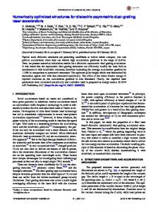
uncertainties on the performance of structural systems under the large deformations that develop, when e.g. a column member is removed from a system. Hence, a building’s progressive collapse resistance is quantified using specific indicators, such as the plastic rotation θ of the steel beams above the ‘damaged’ area of the building (Fig. 1). In [5], ‘high requirements’ on progressive collapse resistance are related to the limitation of the plastic rotation of the steel beams below 6°. In this work, the relative vertical displacement of the two ends of a beam normalized by its length (vertical drift) can be used as an equivalent alternative to plastic rotation. As a rotation of 6° corresponds to a vertical drift of about 10.5%, the maximum admissible vertical drift is taken 10% and is imposed through a related constraint for beam deformation in the optimization procedure presented herein.
Figure. 1. Deformed shape of a frame under a base corner column loss scenario.
3
RETROFIT METHODS
In this section, two retrofit methods are presented. The first method aims to increase the stiffness of the beams, so that deflections caused by the sudden loss of a column are reduced. An alternative to the aforementioned approach, in order to increase the building’s progressive collapse resistance, is to introduce a set of bracings placed in the horizontal direction at predefined storeys. 3.1 Beam retrofit with plates and I-shaped sections When designing against progressive collapse, of particular significance are the horizontal elements, which are inevitably involved in the redistribution of the gravitational loads from the affected bays to the undamaged structural elements and, thereafter, to the ground. Whether they are the main elements of the intended alternate path or they play a secondary role in realizing it, their integrity is crucial for the successful employment of the alternate path method. By strengthening the steel beams, their stiffness is enhanced and, consequently, deflections due to additional loads and support condition alteration are reduced. The flanges of an I-shaped beam are the parts of the section with the largest distance from the section’s centroid and, therefore, they provide almost all of its stiffness about the major axis. Hence, a method commonly used to increase an I-shaped beam’s stiffness about the major axis is the installation (welding) of steel plates at its flanges. Increasing the flanges’ area results in a considerable enhancement to the beam’s flexural capacity. In an existing building, steel beams are typically connected at their top flange to a composite or reinforced concrete slab using shear studs. Therefore, the external surface of the beam’s top flange cannot be accessed, which means that any additional plates would have to be welded at the flange’s internal surface (two parts
3570
Georgios S. Papavasileiou and Dimos C. Charmpis
around the section’s web). Such a procedure is considerably more difficult to execute than operating on the external flange surface. Moreover, the top flange may be inaccessible due to other components connected to the beam’s web or running parallel to it (e.g. hydraulic or electrical installations, horizontal bracings, etc.). Thus, only the welding of a plate at the external surface of the beam’s bottom flange is considered in this work. Instead of installing a flange plate, an additional I-shaped section can be welded or bolted to the bottom flange of the existing beam, as illustrated in Fig. 2. This approach aims to significantly move the centroid of the beam’s steel section and achieve large flange distance in the vertical direction, increasing this way the beam’s flexural capacity and improving the effectiveness of the steel material used. It should be noted that the efficiency of the particular method in retrofitting reinforced concrete beams has been investigated in [12]. For the purposes of the present work, IPE sections have been used as additional components attached to existing steel beams.
Figure. 2. Cross-section of a steel beam connected to a composite slab, retrofitted with an additional I-shaped steel section.
3.2 Installation of bracings in the horizontal direction A method often proposed in practice for high-rise buildings, aiming to reduce the effects of damage in load bearing elements, is the creation of reinforced zones along the height by installing steel bracings across predefined storeys. Such bracings, in combination with neighboring beams and columns, form a truss-like mechanism, which receives the gravitational loads from the damaged bays and transfers them to the undamaged section of the building. In order to distinguish the particular bracings configuration from the ones used against horizontal loads, in the remainder of this work they are referred to as ‘horizontal bracings’ and ‘vertical bracings’, respectively, with regard to the direction along which they are installed. Despite their effectiveness, the use of horizontal bracings is often avoided by designers, as long as the building’s susceptibility to collapse can be dealt with alternative methods. A zone of horizontal bracings occupies the facade of an entire storey, which is undesirable for residential or office buildings. Since this is a purely architectural issue, the particular retrofit approach cannot be injudiciously rejected; therefore, its cost-effectiveness is investigated herein and compared against beam strengthening. A typical configuration of horizontal bracings is illustrated in Fig. 3. For the purposes of this study, installation of horizontal bracings is allowed to take place at three locations: at the second, fourth and sixth storey of the building.
3571
Georgios S. Papavasileiou and Dimos C. Charmpis
Columns 1st – 2nd storey Group 1 (Corner) Group 2 (Peripheral in x-x’ direction) Group 3 (Peripheral in y-y’ direction) Group 4 (Internal)
3rd – 4th storey Group 5 (Corner) Group 6 (Peripheral in x-x’ direction) Group 7 (Peripheral in y-y’ direction) Group 8 (Internal) 5th – 6th storey Group 9 (Corner) Group 10 (Peripheral in x-x’ direction) Group 11 (Peripheral in y-y’ direction) Group 12 (Internal) Beams Group 13 (1st and 2nd storey) Group 14 (3rd and 4th storey) Group 15 (5th and 6th storey) Bracings Group 16 (x-x’ direction) Group 17 (y-y’ direction) Group 18 (Horizontal)
Figure. 3. Building model retrofitted with horizontal bracings (top slab removed for visualization purposes).
4
STRUCTURAL MODELLING & ANALYSIS
All structural analyses were performed using the OpenSEES software [15]. Beams, columns and bracings are simulated as distributed plasticity (fiber) elements. A ‘rigid diaphragm’ is used for the simulation of the composite slabs. Beam-column joints are considered to be able to transfer the full bending moment developed. Column base connections are modelled as fixed supports. A bilinear material model (‘Steel01’) is used for the structural steel components, while the ‘ReinforcingSteel’ material type is used for the longitudinal and transversal reinforcement bars of the composite columns. The ‘Concrete01’ material type is employed for all concrete regions of the composite columns. As illustrated in Fig. 3, the structural elements are grouped according to their location on the floor layout, as well as the storey they belong to. In particular, for the initial optimization performed disregarding progressive collapse resistance constraints, columns are divided into: (a) corner, (b) peripheral in x-direction, (c) peripheral in y-direction and (d) internal columns. Moreover, different groups are defined every two storeys, generating in total 12 element groups for columns. Beams are also grouped every two storeys, but they are not further divided within the same storey, i.e. 3 element groups are produced in total for beams. Finally, two element groups are defined for the vertical bracings: in x- and y-directions. For the retrofit optimization, the same grouping defined earlier for the columns and beams applies for the column and beam retrofit, respectively; three additional element groups are defined for the horizontal bracings, one for each storey they are allowed to be installed at (i.e. second, fourth and sixth storey). In order to evaluate the performance of each candidate optimum structural design of the structure under retrofit, six analyses are performed: (a) a linear static analysis under gravitational loads, (b) two eigenvalue analyses (one for each horizontal direction), (c) two nonlinear pushover analyses (one for each horizontal direction) and (d) a nonlinear pushdown analysis.
3572
Georgios S. Papavasileiou and Dimos C. Charmpis
5
CONFIGURATION OF THE OPTIMIZATION PROBLEM
Instead of applying each retrofit method independently and designing based on a trial-anderror procedure, in this work, an optimization procedure similar to [7] is applied. Its aim is to minimize the total cost of the retrofit materials. The advantage of this procedure is that it does not dictate a particular strategy, such as a localized ‘bridge’-type strengthening over the artificially damaged area, which might not be the most cost-effective strategy [8]. Additionally, it allows the utilization of multiple methods in one retrofit design. Since the unit cost of steel CS is related to its mass (€/tn), while the unit cost of concrete CC depends on its volume (€/m3), the Cost Ratio CR=CC/CS is introduced, in order to convert concrete volume into equivalent steel mass. Hence, the objective function minimized is calculated as the total equivalent steel mass of the retrofit materials: M stot CR VC M S .
(1)
The design variables of the optimization procedure are the section details of the beam retrofit and the horizontal bracings. For the strengthening of beams, plates with thickness from 5mm up to 40mm and sections with sizes from IPE80 up to IPE600 are considered. For horizontal bracings, a total number of 18 standard L-shaped sections are available in the respective database. In the two databases, a ‘zero option’ to avoid the use of either retrofit method is also provided. The performance criteria used in this work, which play the role of the constraints of the optimization problem, can be divided in two groups; the first group includes all individual member checks, while the second group explicitly refers to the structural system behavior. Based on the internal forces yielded by the linear static analysis under gravitational loads, steel beams are checked according to the provisions of Eurocode 3 [16] for their capacity in bending moment, shear and their combination, as well as the respective local and global buckling types; composite columns are evaluated according to Eurocode 4 [17] against biaxial bending, shear force (steel core only), compression and their combination. As the bracings are not considered to participate in the load-bearing system of the undamaged building, their assessment is based on the building’s behavior under the pushover and pushdown analyses. Seismic assessment of the buildings is performed by means of a displacement-controlled pushover analysis up to a targeted top displacement (Δtarget). For the collapse prevention limit state, the maximum interstorey drift should not exceed the limit value of 4% [18]. The constructed discrete optimization problem is solved with a discrete Evolution Strategies algorithm [19], which can effectively handle the discrete design options available. The optimizer is linked with OpenSees to automatically obtain the results from structural analyses needed for the evaluation of the constraints. 6
APPLICATION
A six-storey 5×5-bay composite building is selected for the application of the optimization procedure (Fig. 3). Vertical bracings are installed in both directions at the middle bays. At first, the building is optimally designed by disregarding progressive collapse resistance constraints. Its columns are designed as concrete-encased I-shaped sections. A concrete layer of 5cm around the steel core is assumed, while its reinforcement consists of 10mm longitudinal bars and 8mm stirrups with 10cm spacing. The beams and bracings are modelled as pure steel elements. The section grouping illustrated in Fig. 3, corresponding to equal number of design variables, is used for columns and beams. Instead of retrofit section characteristics, the particular variables take values from two standard section databases: HE100B-HE1000B sections are used for col-
3573
Georgios S. Papavasileiou and Dimos C. Charmpis
umns and IPE80-IPE600 sections for beams. L-shaped sections are used for the vertical bracings in both directions. Hence, 17 design variables are utilized in total (corresponding to the 17 first groups depicted in Fig. 3, i.e. except for group 18) to produce an initial optimized design for the composite building. Table 1 provides the characteristics of the seismically designed building yielded by the optimization procedure.
Columns
Storeys 1-2
Storeys 3-4
Storey 5-6
Corner
HE280B
HE220B
HE200B
Peripheral, x-direction
HE340B
HE260B
HE200B
Peripheral, y-direction
HE400B
HE260B
HE200B
Internal
HE280B
HE280B
HE200B
Storeys 1-2
Storeys 3-4
Storey 5-6
IPE330
IPE330
IPE330
Beams Vertical bracings
x-direction
L90x90x7
y-direction
L90x90x7
Total equivalent steel mass
182.46 tn
Table 1: Optimized seismic design of the composite building disregarding progressive collapse resistance constraints.
As the provisions against progressive collapse were deactivated for the determination of the initial design, its performance under various damage scenarios needs to be evaluated. Three element removal scenarios (Fig. 4) are selected to simulate structural damage. In the first two scenarios, an accident (e.g. collision of a heavy truck on the building) that would result in the loss of a corner and one (ERS1) or two (ERS2) consecutive peripheral columns is assumed. A more destructive event, such as an explosion at the base of the building, is simulated in the third damage scenario (ERS3). The explosion is considered to have affected the first two storeys of the building near its corner. As a result, a number of columns and beams are assumed to be severely damaged and are consequently removed from the model. Referring to the seismically optimized design of Table 1, the maximum vertical drift recorded for scenarios ERS1, ERS2 and ERS3 is 10.6%, 10.8% and 14.6%, respectively. Thus, the maximum admissible vertical drift of 10% set in Section 2 is exceeded, since progressive collapse resistance has not been accounted for obtaining the design of Table 1. It is noted that another damage scenario with only one corner column removed results in a maximum vertical drift of 6.6%, which indicates a sufficient collapse resistance. In order to be able to sustain the aforementioned damage scenarios without excessive extent of structural damage, the building needs to be appropriately retrofitted. In order to improve its performance under the three element removal scenarios, the retrofit methods described in Section 3 are utilized. Thus, the optimized design of Table 1, which has been identified based on Eurocode 3 and 4 provisions and seismic resistance constraints, is optimally retrofitted to resist also progressive collapse with respect to the three aforementioned damage scenarios.
3574
Georgios S. Papavasileiou and Dimos C. Charmpis
(a)
(b)
(c)
2nd storey
1st storey Figure. 4. The three element removal scenarios considered: (a) ERS1 (layout of storey 1 showing the two base columns removed), (b) ERS2 (layout of storey 1 showing the three base columns removed) and (c) ERS3 (threedimensional view of ‘damaged’ building and layout of storeys 1 and 2 showing the structural members removed).
It should be mentioned, however, that retrofitting against progressive collapse should not be limited to the strengthening of the horizontal structural elements or the installation of additional ones. In general, particular attention needs to be paid to the columns as well. Considering the actions the building is required to resist, columns may also need strengthening due to requirements for additional stiffness or tensile force capacity. Hence, in the seismic analysis of the retrofitted building, an increased total mass needs to be taken into account, which is due to the
3575
Georgios S. Papavasileiou and Dimos C. Charmpis
additional material of the retrofit; to avoid a very large fundamental period, an increase in the building’s stiffness may be needed. Moreover, when horizontal bracings are installed at a storey, there is a large increase in the stiffness of the particular storey; if the stiffness of this storey is much larger than that of the storey below, it could result in huge drifts of the columns of the storey below. Furthermore, it was noticed in preliminary analyses that, when buildings with strong beams at the top floors are subjected to element removal scenarios, they seem to develop a ‘suspension mechanism’, in order to transfer the loads from the damaged bays through the undamaged elements to the ground. More specifically, the alternative load path formed utilizes the columns over the bays directly affected by the artificial damage to transfer the loads to the strong top beams and, through them, to the undamaged columns. The above discussion reveals that the retrofit methods described in Section 3, which actually aim at establishing adequate horizontal load paths over the ‘damaged’ area, may not be adequate for the overall structural system, since strengthening of the vertical load paths may also be needed. Therefore, the option to retrofit the building’s composite columns by means of concrete-covered steel cages, as described in [11], is given to the optimization procedure. Thus, a total of 18 design variables are considered based on corresponding section groups: variables 112 control the retrofit of columns, variables 13-15 control the retrofit of beams and variables 16-18 control the placement of horizontal bracings. Fig. 3 illustrates 16 of these 18 design variables; groups 16 and 17 (vertical bracings) are set in the initial optimization for the seismically designed building (Table 1); in retrofit optimization, groups 16 and 17 correspond to the horizontal bracings at storeys 2 and 4, respectively. Table 2 illustrates the optimized retrofit designs obtained when considering each of the three element removal scenarios. For ERS1 and ERS2, the most cost-effective retrofit is achieved by adequately increasing the stiffness of beams. In these two scenarios, a ‘bridge’-type alternate load path is formed by strengthening only the beams of storeys 1-2. The additional steel mass required for ERS1 is particularly high considering the limited extent of the ‘damage’. However, such a result can be anticipated due to the change of the support and loading conditions the beams directly over the ‘damage’. Moreover, the grouping of the beams every two storeys results in a retrofit requirement for both storeys 1 and 2 regardless of the location and extent of the damage. This retrofit requirement could be possibly reduced by defining a different beam group for each storey. When an additional neighboring column is removed for ERS2, only about 30% additional steel mass is needed compared to the requirement for ERS1. Apparently, the loss of an additional peripheral column in ERS2 is a less significant ‘damage’ compared to the members lost in ERS1. Finally, for the significantly more severe ‘three-dimensional’ damage scenario ERS3, beam retrofit appears to be less cost-effective than the use of horizontal bracings. For this rather aggressive damage scenario, more than double retrofit material is required than for ERS2. To gain better insight on the effectiveness of the retrofit methods, sub-optimal designs are presented in Table 3 for the three damage scenarios. The designs this table are obtained by allowing only beam retrofit for ERS3 (the option to install horizontal bracings is deactivated), while only horizontal bracings are allowed for ERS1 and ERS2 (the option to retrofit beams is deactivated). Thus, Table 3 gives retrofit designs using alternative methods to the ones identified in Table 2. A comparison between the designs of Tables 2 and 3 reveals that, for ERS2, the two retrofit methods produce practically the same total retrofit cost. For ERS1, installing horizontal bracings induces a material cost that is about 35% more costly than the one corresponding to beam retrofit. For ERS3, the retrofit of beams costs about 60% more that the placement of horizontal bracings. Despite the architectural and operational implications introduced by horizontal bracings, this is a much more cost-effective solution for ERS3 and cannot be easily rejected for non-structural reasons. It is also interesting to notice that the designs for ERS1 and
3576
Georgios S. Papavasileiou and Dimos C. Charmpis
ERS2 in Table 3 activate a ‘suspension mechanism’ by introducing horizontal bracings at the top storey. For ERS3, an overall structural system upgrade is realized by strengthening all beams along the building’s height, avoiding just the activation of a ‘bridge’ over the ‘damaged’ area.
Beam retrofit
Horizontal bracings
Total equivalent steel mass
Storeys of application
1-2
3-4
5-6
2
4
6
Group number
13
14
15
16
17
18
ERS1
10mm plate -
-
-
-
-
15.2 tn
ERS2
IPE180
-
-
-
-
-
19.8 tn
ERS3
-
-
-
L90x90x7
L90x90x7
-
40.9 tn
Total equivalent steel mass
Table 2. Optimized retrofit designs.
Beam retrofit
Horizontal bracings
Storeys of application
1-2
3-4
5-6
2
4
6
Group number
13
14
15
16
17
18
ERS1
-
-
-
-
-
L90x90x7
20.5 tn
ERS2
-
-
-
-
-
L90x90x7
20.5 tn
ERS3
30mm plate 10mm plate 25mm plate
-
-
-
65.3 tn
Table 3. Sub-optimal retrofit designs.
An important observation regarding all retrofit designs of Tables 2 and 3 is that columns do not actually require strengthening. Despite the increase of the total seismic mass due to the added retrofit material of beams or horizontal bracings, the additional stiffness introduced in the structural system either by the beam retrofit or by the horizontal bracings seems to balance the effect of the additional mass. Moreover, in the optimized designs of Table 2 for ERS1 and ERS2, the ‘bridge’-type strengthening of the beams directly over the location of the ‘damage’ serves as a ‘support’ for all storeys above and leaves the respective load paths unaffected. This mechanism prevents the development of tensile forces at the columns over the ‘damaged’ area, so the column sections identified for seismic demands suffice also for progressive collapse resistance. It is finally emphasized that the fact that column strengthening is not required for the particular retrofit cases of the present study does not imply that the same applies generally, as each building’s performance and retrofit requirements may vary significantly.
3577
Georgios S. Papavasileiou and Dimos C. Charmpis
7
CONCLUSIONS
In this paper, two retrofit methods for steel-concrete composite buildings to resist progressive collapse were assessed. A building previously optimized to satisfy Eurocode 3 and 4 provisions and seismic resistance constraints was optimally strengthened to meet requirements on progressive collapse resistance. Optimized retrofit designs have been identified using beam strengthening or installation of horizontal bracings, in order to provide the structure with sufficient collapse resistance with respect to three element removal scenarios corresponding to artificially introduced damage of varying extent. The patterns of the optimized retrofit designs verify the findings of previous studies [7,8], according to which the establishment of adequate horizontal load paths within a locally damaged building is a key aspect in attaining progressive collapse resistance. Inevitably, additional design requirements on progressive collapse resistance lead to increased structural costs due to the need for extra material. The results obtained in this study demonstrate that the structural optimization approach presented is capable of producing costeffective retrofit designs. Coping with progressive collapse in an optimal way is critical, in order to maintain the extra cost induced as low as possible, hopefully within affordable limits.
REFERENCES [1] B.R. Ellingwood, D.O. Dusenberry, Building design for abnormal loads and progressive collapse. Computer-Aided Civil and Infrastructure Engineering, 20, 194-205, 2005. [2] U. Starossek, M. Wolf, Design of collapse-resistant structures. In: Proceedings of JCSS and IABSE Workshop on Robustness of Structures, Building Research Establishment, Garston, Watford, UK, 2005. [3] R.S. Nair, Preventing disproportionate collapse. Journal of Performance of Constructed Facilities, 20, 309-314, 2006. [4] J.D. Sørensen, H.H. Christensen, Danish requirements for robustness of structures: Background and implementation. Structural Engineering International, 16, 172-177, 2006. [5] Department of Defense (DoD), Unified Facilities Criteria (UFC) – Design of buildings to resist progressive collapse. UFC 4-023-03, Washington, DC, USA, 2009. [6] M.H. Faber, Robustness of structures – Final report of COST action TU0601. COST (European Cooperation in Science and Technology), EU, 2011. [7] D.C. Charmpis, G.S. Papavasileiou, Designing against earthquake and progressive collapse – A structural optimization approach applied to composite steel-concrete buildings. In: Proceedings of 7th European Conference on Steel and Composite Structures (EUROSTEEL 2014), Naples, Italy, 2014. [8] D.C. Charmpis, A. Kontogiannis, The cost of satisfying design requirements on progressive collapse resistance – Investigation based on structural optimization. Structure and Infrastructure Engineering, 2015, http://dx.doi.org/10.1080/15732479.2015.1038725. [9] Y.-F. Wu, T. Liu, D.J. Oehlers, Fundamental principles that govern retrofiting of reinforced concrete columns by steel and FRP jacketing. Advances in Structural Engineering, 4, 507-533, 2006.
3578
Georgios S. Papavasileiou and Dimos C. Charmpis
[10] K.G. Vandoros, S.E. Dritsos, Concrete jacket construction detail effectiveness when strengthening RC columns. Construction and Building Materials, 22, 264-276, 2008. [11] G. Papavasileiou, D.C. Charmpis, N.D. Lagaros, Optimized seismic retrofit of steel-concrete composite frames, In: Proceedings of 3rd ECCOMAS Thematic Conference on Computational Methods in Structural Dynamics and Earthquake Engineering (COMPDYN 2011), Corfu, Greece, 2011. [12] X.S. Ren, B. Zhou, Design and analysis of reinforced concrete beam retrofitted by externally bonded H-type steel member. Procedia Engineering, 14, 2133-2140, 2011. [13] G.E. Thermou, S.J. Pantazopoulou, A.S. Elnashai, Global interventions for seismic upgrading of substandard RC buildings. ASCE Journal of Structural Engineering, 138, 387401, 2012. [14] D.C. Charmpis, M.C. Phocas, P. Komodromos, Optimized retrofit of multi-storey buildings using seismic isolation at various elevations: assessment for several earthquake excitations. Bulletin of Earthquake Engineering, 2015, http://dx.doi.org/10.1007/s10518015-9737-y. [15] S. Mazzoni, F. McKenna, M. Scott, G.L. Fenves, Open System for Earthquake Engineering Simulation, OpenSees Command Language Manual, PEER Center, California, USA, 2006. [16] EN 1993-1-1, Eurocode 3: Design of steel structures – Part 1-1: General rules and rules for buildings. European Committee for Standardization (CEN), Brussels, Belgium, 2005. [17] EN 1994-1-1, Eurocode 4: Design of composite steel and concrete structures – Part 1-1: General rules and rules for buildings. European Committee for Standardization (CEN), Brussels, Belgium, 2004. [18] American Society of Civil Engineers (ASCE), Seismic rehabilitation of existing buildings. Standard ASCE/SEI 41-06 (including Supplement No. 1), Reston, Virginia, USA, 2006. [19] N.D. Lagaros, M. Papadrakakis, G. Kokossalakis, Structural optimization using evolutionary algorithms. Computers and Structures, 80, 571-589, 2002.
3579