Proceedings, XVII IMEKO World Congress, June 22 – 27, 2003, Dubrovnik, Croatia
TC1
Proceedings, XVII IMEKO World Congress, June 22 – 27, 2003, Dubrovnik, Croatia
TC3
XVII IMEKO World Congress Metrology in the 3rd Millennium June 22−27, 2003, Dubrovnik, Croatia
PARAMETRICAL MODELING OF THE STRAIN GAUGED FORCE AND/OR PRESSURE TRANSDUCERS Dan Mihai Stefanescu*, Lia Dolga**, Adrian Marinescu*** *National Institute for Aerospace Research, Bucharest, Romania, **“Politehnica” University of Timisoara, Romania, ***“Politehnica” University of Bucharest, Romania Abstract − The paper deals with a strain gauge transducer that can alternatively measure force or pressure. The functional employment of the transducer is explained. In determining the optimal geometry of the elastic element, the authors employ the parametric and feature based CAD modeling, together with the finite element analysis. This ensures flexible and interactive modifications of the geometry and the correlation with the manufacturing process. Finally, the optimal solution is translated and stored in STEP format, a system independent geometric model that is compatible with any modeling environment.
F
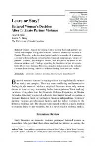
Figure 1 The alternative measuring of force and pressure in the trisonic wind tunnel
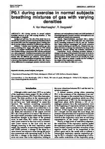
Authors considered a composite solution, starting from the property of the planar plates to sense both pressure p (force distributed on the whole surface) and concentrated force F (in the plate centre). Therefore, the unique transducer presented in Figure 2 has a simple construction, planar membrane with a central protuberance, and a “double” functionality: the four Wheatstone bridged strain gauges, emplaced on the opposite face to the pressure application, sense either the pressure or the pressing force.
Keywords: strain gauge measurement, force, pressure 1.
INTRODUCTION
M5
4
Several technical applications require the alternatively measuring of the force and the pressure. The determination can be done using the best-suited elastic element in this respect namely membrane or diaphragm. In this paper, four types of membranes are compared: circular, square, rectangular and oval ones. Their analytical formulae are rather complicated, so the finite element analyse (FEA) is the most valuable numerical method to optimise these elastic elements. With the aim of easy modifying the elements dimensions, the authors generated a parametric CAD model for each of them. The final CAD models will be translated into a neutral-format model, which is system independent. 2.
p’ p
1x45°
16
6
3
Ø2
Ø80 Ø5,5(10 holes equidistant)
Ø105
R1
ALTERNATIVE MEASUREMENT OF FORCE AND PRESSURE
Ø95
R2
Adapting the trisonic wind tunnel for terrestrial vehicle testing procedures brings up interesting metrological/ instrumentation problems. Blowdowns acting on high-speed models placed on a special moving belt require the optimum combination of the pressing force (the belt weight) and the suction pressure (to maintain the proper belt position) (Figure 1). Two independent transducers control the loop measurement of the pressure differences (0,8 MPa) between the two faces of the moving belt active part: - a classical pressure transducer on the upper face; - a (com)pression transducer on the lower face, summing the aerodynamic pressure and the pressing force of the belt [1].
R4 R3
Figure 2 The geometrical shape of the proposed elastic element 393
Proceedings, XVII IMEKO World Congress, June 22 – 27, 2003, Dubrovnik, Croatia Proceedings, XVII IMEKO World Congress, June 22 – 27, 2003, Dubrovnik, Croatia
3.
STRAIN GAUGED MEMBRANE TYPES
TC1 TC3
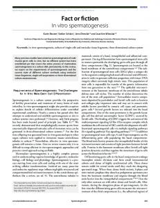
(Figure 3 a, b). If the classical circular membranes are frequently used, the square membranes are useful for tactile sensors [2], [3] and the rectangular ones for surfacemicromachined piezo-resistive pressure sensors [4].
The paper comparatively considers four types of membranes: circular, square (quadrate), rectangular and oval
a)
b) Figure 3 Results of the FEA applied on membranes of different shapes, loaded by a force F (a), respectively a pressure p (b)
394
Proceedings, XVII IMEKO World Congress, June 22 – 27, 2003, Dubrovnik, Croatia
TC1
Proceedings, XVII IMEKO World Congress, June 22 – 27, 2003, Dubrovnik, Croatia
The analysis is completed with the oval membrane, like a combination of the circular and rectangular ones. Their analytical formulae are complicated [5], consequently the finite element method was considered to optimise these elastic elements. Due to their structural symmetry, it is sufficient to analyse a quarter of the diaphragm. Mesh generation, together with the longitudinal strain εL and the tangential strain εT diagrams, for the best strain gauges positioning, are presented. The circular membrane is the preferred alternative, due to a more difficult manufacturing of the other shapes and to a more difficult fastening along the edge of the membrane, nears the corners. On the square membrane, one can outline a stress concentration at the middle of the edges when loading it with a concentrated force. This represents an inconvenient stress state. The rectangular shape amplifies the strains in the central region, which corresponds to the initial square (about twice). The oval-shaped membrane causes a better stress concentration, increasing the sensitivity, while avoiding the corner fastening. A comparison between the F loading and the p loading on the same membrane shape outlines the changing of the stress and strains distribution. This difference is higher on the square and rectangular membranes, where even the concavity of the strain curve visibly changes. Based on the early considerations regarding the shape of the sensitive region, in the following stage of the study, only the circular membranes were considered. In addition, shape optimisation of the circular membranes aims to increase the tensometrical sensitivity. A personal example of “profiling” tensometrical membranes in order to increase their sensitivities is shown in [1]. 4.
TC3
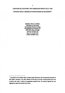
Figure 4 The CAD model of the elastic element (geometric shape, tree and design variables)
PARAMETRICAL MODELING OF THE STUDIED CIRCULAR MEMBRANES
The parametric CAD modeling method was used to flexibly generate, modify and interactively optimise the geometry of the elastic element. The shape was therefore generated based on different design features, parametrically defined and specifically corresponding to different manufacturing operations (Figure 4). Changes could be effortless made on the parametric model, both on features and on dimensions. The parametric model was interactively refined based on the finite element analysis; finally, the optimal 3D shape was established. The corresponding force- and pressure ranges are: 0-1 kN, respectively 0-2 MPa. Current CAD procedures facilitated the integration and the concurrent developing of all the design stages. Different design stages evolved simultaneously, because one induces interactive changes in another stage. Fast and optimal design solutions for the elastic element were consequently created. Based on the maximal stressed regions (Figure 5), the strain gauges disposal was established, taking into consideration the full bridge connection, as it is presented in Figure 6.
Figure 5 The stressed structure of the parametric CAD model
R1
R4
R2
R3
Figure 6 The full bridge connection of the strain gauges
395
Proceedings, XVII IMEKO World Congress, June 22 – 27, 2003, Dubrovnik, Croatia
TC1
Proceedings, XVII IMEKO World Congress, June 22 – 27, 2003, Dubrovnik, Croatia
The final shape of the parametric CAD model was translated into a neutral-format model, defined by the Standard for the Exchange of Product Model Data (ISO 10303, STEP). The STEP translated model is in accordance with the AP203 conformance class 6 [6], which represents shapes by advanced B-rep (boundary representation). The application context corresponds to the configuration controlled 3D designs of the mechanical parts and assemblies. The application protocol definition is:
5. CONCLUSIONS The above-presented strain gauge transducer ensures the alternative real-time determination of two mechanical parameters: force and pressure. The transducer can be used in measuring systems that permanently require both types of data. The authors demonstrated that a systematic geometrical determination of the elastic element and a careful calibration of the transducer ensure a high-quality measuring device. Up-to-date computer-aided study methods were applied all along the study, to facilitate a fast and optimal design of the elastic element.
'INTERNATIONAL STANDARD', 'config_control_design', 1995. The authors will translate in the future the CAD representation into a STEP-NC model, based on the STEP-NC international standard, which defines a machine independent data input pattern for Computerized Numerical Control (CNC) systems [7]. The translation will facilitate the immediate manufacturing of the elastic element and the long-distance transmission of the designed solution, through Internet, to any manufacturer. A comparison with the theoretical model was completed with the purpose of evaluating the CAD solution. The used equations for the strain ε correspond to the classical theory known in the strength of materials domain. These analytical dependences are given in the relationships (1), where εp is the strain determined by the pressure p and εF is the strain determined by the force F. ε p = 0,865
REFERENCES [1] Stefanescu D.M., “Methods for increasing the sensitivity of strain gauged force transducers”, Ph D thesis, “Politehnica” University of Bucharest, Romania, 1999. [2] Bütefisch S., Dauer S., Büttgenbach S., “Silicon threeaxial tactile sensor for the investigation of micromechanical structures”, Sensor’99 Congress, Vol. 2, pp. 321-326 Nurnberg, Germany, 1999. [3] Bütefisch, S., Büttgenbach, S., Kleine-Besten, T., Brand U., “Silicon Three-Axial Tactile Sensor For Micromaterial Characterisation”, Institute for Microtechnology, Technical University of Braunschweig, Germany, 1999, www.tubs.de/institute/imt/mitarbeiter/buetefisch. [4] Lisec T., Stauch H., Wagner B., “Surfacemicromachined piezoresistive pressure sensor”, Sensor’95 Congress, A 1.2, Nurnberg, Germany, 1995. [5] Young W.C., “Roark’s Formulas for Stress and Strain”, Sixth Edition, ISBN 0-07-072541-1, Society for Experimental Mechanics, Bethel, CT, 1996. [6] Teresko J., "The Next STEP", Industry Week, March 5, 2001, pp. 17-19. [7] www.steptools.com.
pa 2
Eh2 ε F = 0,95 F Eh2
TC3
(1)
The used parameters of the above relationships have the following significances:
Authors: *Dr. Dan Mihai Stefanescu, National Institute for Aerospace Research, Bucharest, Romania, Mailing address: Bd. Iuliu Maniu 220, Bucharest - 77538, Romania, Phone: + 4021 434 00 79, Fax: + 4021 434 00 82, e-mail:
[email protected] **Dr. Lia Dolga, “Politehnica” University of Timisoara, Romania, Mailing address: Faculty of Mechanical Engineering, Dep. of GDDT, B. M. Viteazu Nr. 1, Timisoara - 1900, Romania, Phone: + 40 256 403739, Fax: + 40 256 204295, e-mail:
[email protected] ***Dr. Adrian Marinescu, “Politehnica” University of Bucharest, Romania, Faculty of Engineering and Management of Technological Systems, Mailing address: Splaiul Independentei 313, Bucharest – 77206, Romania, Phone: +4021 402 93 73, Fax: +4021 402 93 73, e-mail:
[email protected]
p = the distributed applied pressure, F = the concentrated applied force, E = the Young’s modulus of the material, h = the constant thickness of the membrane, a = the inner radius of the membrane (determining the sensitive region). The comparison outlined a close similarity between the CAD model of the elastic element and the analytical model of the same element.
396