Orchestration Services for Distributed Multimedia Synchronisation Andrew Campbell, Geoff Coulson, Francisco García, and David Hutchison Computing Department, Lancaster University, Lancaster LA1 4YR, UK E.mail:
[email protected]
Abstract Rapid developments in networking technology over the past few years have lead to the emergence of distributed applications which incorporate continuous media data types such as digital video and audio. Such applications have stringent real-time synchronisation requirements which have been documented in the literature. However, little research has been carried out into suitable mechanisms to support such synchronisation. This paper presents a multimedia synchronisation architecture and a detailed description of the lower layer services of the architecture. The paper also provides a rationale for the services by describing a real world application area and illustrates how the services can be exploited in this application area. Because the services described incorporate a variety of co-ordination functions over multiple transport connections a more general term, orchestration, is introduced to describe the low level synchronisation services. Keyword Codes: C.2.2; C.2.4 Keywords: Computer-Communication Networks, Network Protocols; Distributed Systems 1. INTRODUCTION Rapid developments in networking technology over the past few years have lead to the emergence of distributed applications which incorporate multimedia and continuous media information exchange [1] (e.g. digital video and audio). Such applications introduce new design challenges at all levels from network protocols and operating systems to application support platforms. This is because multimedia applications introduce fundamentally novel requirements [2] such as the need to represent continuous media storage and transmission, quality of service (QOS) configurability and real-time synchronisation of continuous media streams. This paper addresses the requirement for real-time synchronisation of continuous media streams. Our approach is based on the assumption that the underlying transport protocol supports a degree of QOS configurability and has responsive back pressure flow control. Previous work at Lancaster has addressed these issues and is reported in [3]. In this paper we describe layers on top of such a protocol which support application level synchronisation between multiple information streams. These services also provide support for synchronisation and rate control within single streams. Because of the scope of the services, we introduce a new term, orchestration, which is defined as the dynamic management of information flow and QOS in a multimedia session involving a set of connections and end devices.
The paper first sets out, in section 2, requirements for synchronisation in distributed multimedia applications which are set in the context of a real world application scenario. Section 3 then introduces our orchestration services including an architecture which places the services within an experimental distributed multimedia application platform developed at Lancaster. Finally, section 4 presents an application example from the scenario of section 2 which exercises the orchestration services, and section 5 presents our conclusions. 2. SYNCHRONISATION REQUIREMENTS 2.1 Application Scenario Previous work in the field has identified the need for real-time synchronisation between related activities in multimedia applications (e.g. [4-6]). This section illustrates such requirements in the context of a real world application scenario which arose from a collaboration between Lancaster University and ICI, Runcorn, UK [7]. The scenario is one of remote scientific co-operative working. ICI maintains a number of specialised microscopes at various sites throughout the country and employs scientists who use the various microscopes on a regular basis. Currently, scientists need to travel between sites to use microscopes and to collaborate with remotely sited colleagues on microscope output data. In the latter case, microscope output (usually slow scan video) is dumped to videotape and taken along by car. To reduce travelling overheads and improve the efficiency of collaboration, we have designed a prototype system which allows remote collaborative working between scientists at the various sites. Presently the system runs over a local network but should be capable of running over a wide area network without fundamental design changes. Each scientist has a audio/ video multimedia workstation with the capability to control and display the slow scan video output from remote microscope devices. Such output can also be multicast to a number of sites which are linked by a multiparty video telephone component. Finally, scientists engaging in remote collaborative working can record microscope output to disc and create multimedia documents including co-ordinated video, text and voice annotations. They may also send such documents to remote sites as ‘video mail’. 2.2 Synchronisation Scenarios To begin to address the requirements of multimedia synchronisation, we have identified two categories of synchronisation as follows:event-driven synchronisation: This is the act of notifying that a relevant event or set of events has taken place, and then causing an associated action or actions to take place. This must all be done in a timely manner due to the real-time nature of continuous media communication. For example, a user clicking on the stop button relating to a video play-out should cause the play-out to stop instantaneously. continuous synchronisation: This is an on-going commitment to a repetitive fine grained pattern of event driven synchronisation relationships such as the 'lip sync' relationship between the individual frames in an audio and video components of a play-out. Continuous synchronisation is ultimately based on event synchronisation but is a useful concept in itself as it permits potentially complex patterns of event synchronisation, perhaps involving various degrees of ‘slack’ and tolerance, to be encapsulated and handled as a whole. To illustrate the applicability of the concepts of event driven and continuous synchronisation, we can extract a number of situations from the application scenario introduced
above:event synchronisation A caption is to be shown at a particular point in a microscope video segment. event synchronisation with user interaction The user hits a graphical user interface button to start/stop continuous information flow (perhaps over multiple flows simultaneously). lip synchronisation This is the most commonly cited form of multimedia synchronisation. It appears in our scenario as the need to synchronise the video and audio components in the playback of a recorded videophone message (i.e. video mail). In such cases, video and audio are almost always stored in separate files and sometimes on separate storage servers which are optimised for different media [8]. continuous synchronisation other than lip synchronisation This is illustrated by the playback of two simultaneously recorded video segments which record the same experimental sample from two different perspectives. An example of this is where recordings of different magnification are made and then simultaneously replayed to convey an impression of the context of the higher magnification. continuous synchronisation requiring varying degrees of 'tightness' Simultaneously recorded video perspectives must be played in precise frame by frame synchrony so that relevant features may be simultaneously observed. On the other hand, lip synchronisation in multimedia documents does not need to be absolutely precise when the main information channel is auditory and video is only used to enhance the sense of presence. It is useful to permit degrees of tightness of continuous synchronisation as looser synchronisation is often sufficient and can be achieved with a relatively low overhead. continuous synchronisation of many streams This occurs in multimedia documents where an audio annotation, perhaps with accompanying video, is associated with microscope output clips involving one or more video streams. continuous synchronisation from disparate sources and sinks The need for continuous synchronisation arises in a number of different physical node configurations. For example, video and audio from separate remote sources often need to be synchronised at a common sink. Conversely, the playout of a single segment of stored microscope may need to be displayed simultaneously at different remote sinks so that scientists discussing the output over a videophone can simultaneously refer to the same features. There are also situations where two or more streams need to be synchronised which all originate from different sources and are played out at separate remote sinks. For example, two remote scientists may each view different separately stored perspectives on the same experiment while discussing related events over the videophone. Finally, there is a need to synchronise separate multicasted playouts where, for example, a number of scientists interactively collaborate over a continuously synchronised playout where the components are separately stored.
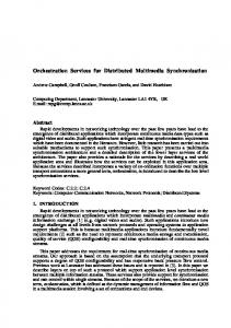
2.3 Infrastructure Requirements for Continuous Synchronisation Although it is possible in some situations to support continuous synchronisation simply by multiplexing the different media onto a single connection in the correct ratios, there exist strong arguments against this as a general solution [9]:• ּ the overhead and complexity of multiplexing/ demultiplexing is significant, especially when different encoding/ compression schemes are used for different media; this can lead to excessive real-time delays, especially where it would otherwise be possible to interface the transport protocol directly to hardware such as frame grabbers, codecs etc.; • ּ the opportunity to process separate connections in parallel is lost, thus reducing potential performance; • ּ multiplexing leads to a combined QOS which must be sufficient for the most demanding medium; this may be both expensive and unsuited to some component media types; • ּ multiplexing is not an option where media originate from different sources. If multiplexing is rejected as a general purpose strategy for the support of continuous synchronisation, an analysis of the continuous synchronisation problem suggests that the following support should be provided by the infrastructure. Sections 3 and 4 illustrate how our design satisfies these requirements. i) the ability to start and stop and pause related continuous media data flows precisely together. If a temporal relationship is not correctly initiated, there is no possibility of maintaining correct synchronisation. ii) the ability to monitor the on-going temporal relationship between related connections, and to regulate the connections to perform fine grained corrections if synchronisation is being lost. It is almost inevitable that related connections will eventually drift out of synchronisation due to factors such as the potentially long duration of continuous media connections in typical applications, and temporary 'glitches' occurring in individual connections and the scheduling of source and sink application threads. Finally, note that the need for the comprehensive continuous synchronisation support detailed in this paper is only strictly necessary when all the CM sources to be orchestrated are stored. This is because with live media, there is no possibility of control over when the information flow starts (e.g. it depends when the camera is switched on!), and also no possibility of altering the speed of a live media flow. Whenever live sources are to be continuously synchronised (e.g. the output from a camera and a microphone), the major requirement is to ensure that the latency of the connections is the same. Other QOS parameters such as delay, jitter and error rates can be separately controlled over individual connections as desired. 3. ORCHESTRATION ARCHITECTURE This section presents an architecture which addresses the need for the temporal coordination of multiple related continuous media transport streams identified in section 2. It can be seen from the architecture diagram in figure 1 that orchestration is a multi-layered activity. Each layer provides policy to its lower neighbour and mechanism to its upper neighbour. This design provides both flexibility and efficiency because the lower layers are simply provided with targets, and all exceptions, error handling and re-structuring are handled in the layers above. 3.1 Upper Architectural Layer The top level of the synchronisation architecture forms part of the Lancaster multimedia application platform [10]. This is an object-based set of services based on the ANSA distributed
systems architecture [11]. At the application platform level all entities in the system are represented as abstract data type interfaces with named operations which can be invoked by RPC. Such entities include documents, the individual components of documents, 'devices' such as video windows and speakers, and even continuous media connections themselves. Abstract data type interfaces are referred to through interface references which are location independent 'handles' which can be freely passed around the system. Sync. Manager OSI ULA
HLO
HLO
Key: HLOHigh level Orchestrator
LLO
LLO
LLO Low level
OSI 1-4
Orchestrator
ULA OSI Upper
protocol stacks Single node
Layer Architecture
Single node
Figure 1: Three level orchestration architecture. The synchronisation manager is the platform level view of the orchestration services and, like all the other platforms services, appears to applications as an abstract data type interface. The synchronisation manager is responsible for finding the physical locations of the transport connections underlying the platform level communications abstractions, and thus choosing a single node from which the lower levels of orchestration will be co-ordinated. The node selected, known as the orchestrating node, is that common to the greatest number of connections (see figure 2). For example, if it was required to orchestrate separate video and audio tracks of a film stored on separate storage servers, the common sink would be designated as the orchestrating node by the synchronisation manager. The platform level of the architecture is not discussed further in this paper. See [10] for more details of this aspect of the architecture. A more detailed description of the synchronisation specific aspects of the platform can be found in [12]. orchestrating node
HLO
LLO
orchestrating node
LLO
HLO
Figure 2: Orchestrating at the common node. 3.2 Lower Architectural Layers Below the platform level, the remaining two orchestration components are responsible for realising the behaviour and policy required by the synchronisation manager. At this level, the orchestration process is realised as high level orchestrator (HLO) entities which monitor and regulate multiple transport connections via a low level orchestrator (LLO) interface. For each orchestrated group of connections, a single HLO runs on the orchestrating node, and an LLO instance runs on all source and sink nodes of all the orchestrated connections. The HLO only interacts with its local LLO instance, but the multiple LLO instances interact with each other via
Orchestrator PDUs (OPDUs), on out of band connections. 3.2.1 Orchestration Control Framework The out of band connections for OPDU transfers must have guaranteed bandwidth to support the necessary real-time communication of orchestration primitives and, in general, a separate connection is required between the orchestrating node and each source and sink node involved. However, depending on the topology the numbers of connections can often be reduced in practice: e.g. when a number of connections are sourced and sinked on the orchestrating node itself. In our current implementation we exploit duplex control connections associated with each simplex continuous media connection [13]. There are three sorts of interaction between the HLO and the LLO instance on the orchestrating node, each of which involves a separate set of primitives. The first group of primitives are used for management purposes to establish and modify orchestrated groups of connections. The second set operates over a grouping of transport connections and provides the ability to atomically prime, start and stop the flow of data in these connections both atomically and instantaneously. The third set allows the HLO to control the rate of information flow on individual orchestrated connections, and thus forms the basis for the implementation of continuous synchronisation across multiple connections.
1
2 Interval
3
Regulate.indication
Regulate.request
Regulate.indication
Regulate.request
Regulate.request
Regulate.indication
High Level Orchestrator
Low Level Orchestrator 4 5 6 7 8 9 10 Interval
11
12
Interval
TIME LINE
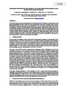
Figure 3: Interaction between HLO and LLO.
Regulate.request
Figure 3 illustrates the pattern of interaction for a single connection between the HLO and the local LLO where the third set of primitives are being applied. The HLO supplies the LLO with rate targets for each orchestrated connection over specified intervals. These targets require that each orchestrated connection runs at the required rate for the required synchronisation relationship between the orchestrated connections to be maintained. The LLO attempts to meet the required rate target over each interval for each connection, and reports back at the end of the interval on its actual success or failure. Then, on the basis of these reports, the HLO may set new targets for the next interval which compensate for any relative speed up or slow down among the orchestrated connections. If no new target is set for the forthcoming interval, the LLO uses the rate specified in the previous request until further notice. The LLO operates on a best effort principle; it is the responsibility of the HLO to take appropriate action (e.g. set new targets or re-negotiate the connection QOS) if the LLO consistently fails to meet targets. The length of interval chosen largely determines the granularity or 'tightness' of the synchronisation required (as specified by the application). As mentioned in section 2, loose synchronisation based on long intervals is relatively cheap in terms of message exchanges and synchronisation overhead.
3.2.2 Data Transfer in Orchestrated Connections The small numbered arrows in figure 3 represent the delivery of quanta of CM information which are released by the sink LLO instance to the application thread at times determined by the HLO initiated targets. These quanta are known as OSDUs, and are the units of CM information meaningful to applications (e.g. video frame or text paragraph). The orchestration services maintain a special OSDU sequence number field for each OSDU, which starts from zero when the connection is first used; a second such field, known as an event field, is employed for use by the Orch.Event primitive (see later). Both these fields form part of an OPDU which is sent along with each OSDU. OSDU and OPDU boundaries are maintained by the transport service. This is possible in our system because, at connection establishment time, the transport service is given the maximum size of an OSDU as a QOS parameter, and this (plus the size of the OPDU) is interpreted as a lower bound on buffer size allocation. shared buffer protocol thread
application thread LLO
access semaphores
Figure 4: Shared buffer interface between application and protocol threads. The application’s data.request and data.indication interface to the orchestration service is implemented as a circular shared buffer (see figure 4) which maintains mutual exclusion and access control by means of semaphores. The protocol and application run as separate threads and do not need to explicitly synchronise via the access semaphores if they are running at compatible rates. When applications write/ read OSDUs into/ from the circular shared buffers, they write/ read from the beginning of a buffer, and may also write/ read the current OSDU size to/ from an auxiliary memory location. The LLO operates largely by controlling the flow of data by means of the shared buffer access semaphores. The interface and mechanism of the LLO is described in the following section. 4. LOW LEVEL ORCHESTRATOR The LLO service interface consists of three sets of OSI-like primitives corresponding to the three types of HLO/LLO interaction described above. As indicated above, the LLO interface is not expected to be used directly by applications but is intended for use by an HLO instance and ultimately via a synchronisation manager interface by an application running in an object-based computational model. We now present the LLO interface primitives in more detail together with their implementation in terms of protocol message exchanges. 4.1 Management Primitives The management primitives and their parameters are illustrated in table 1 below. 4.1.1 Orch.request We assume that before an HLO instance attempts to instantiate an LLO orchestrating service, the connections to be orchestrated have already been established.
The initiating HLO issues a Orch.request to the orchestrating LLO instance at its local node. This causes the orchestrating LLO to open transport associations between itself and the LLO instances at the source and sink of all connections in the orchestrated group. Subsequently, the orchestrating LLO instance uses these associations to pass an Orch.request to all the LLO instances involved. Each source and sink LLO instance passes an indication up to the application thread which owns the connection and waits for either an Orch.response or an Orch.release.request depending on whether or not the application wants the connection to be involved. Each LLO instance then replies on its private connection to the initiating LLO with either an Orch.confirm or an Orch.release.request packet. If accepted by all the remote LLO services, the HLO will eventually be passed an Orch.confirm, or if rejected a Orch.Release.indication giving a reason why orchestration was rejected. Apart from refusal by the application, rejection may also occur because some LLO instance has no table space available, or because one or more of the specified connections do not exist etc.. Having authenticated the set of connections to be orchestrated, the orchestrating LLO instance enters the connection identifiers and the corresponding source and sink addresses in a private table accessible via the orch-session-id. Primitives Orch.request Orch.indication Orch.response Orch.confirm Orch.Release.request Orch.Release.indication Orch.Release.response Orch.Release.confirm Orch.Add.request Orch.Add.indication Orch.Add.response Orch.Add.confirm Orch.Remove.request Orch.Remove.indication Orch.Remove.response Orch.Remove.confirm
Parameters orch-session-id, list-of-vc-ids " orch-session-id, vc-id, status " orch-session-id, vc-id " orch-session-id, vc-id, reason " orch-session-id, vc-id " orch-session-id, vc-id, status " orch-session-id, vc-id " orch-session-id, vc-id, status "
Table 1: Orchestration management primitives together with their associated parameters. 4.1.2 Orch.Add and Orch.Remove The Orch.Add and the Orch.Remove primitives are employed to either add or remove a connection or connections from an orchestrated group. The message sequence is similar to that for Orch.request. Note that when connections are removed from an orchestrated group they are not disconnected and thus data may still be flowing. If a single connection is closed, the local LLO instance is informed by the transport service and issues a Orch.Remove.request to the orchestrating LLO instance. 4.1.3 Orch.Release An entire orchestration session is released by issuing a Orch.Release.request. Again, the message sequence is similar to that for Orch.request. Orchestration will also be released implicitly if all the connections in an orchestrated session are closed.
4.2 Group Operation Primitives The primitives to prime connections, and atomically start and stop the data flow on groups of orchestrated connections are illustrated in Table 2. 4.2.1 Orch.Prime The prime mechanism has the effect of filling the end-to-end pipeline of buffers in a connection and is used to ensure that multiple streams of remotely stored CM data can be started together in a co-ordinated manner. It is also useful in ensuring that time critical data can be prefetched and made available when required. A third application of Orch.Prime arises when it is required to flush the buffers in an end to end connection. This need arises when a user stops a media play-out and then wishes to seek to another part of the media before resuming. If the buffers were not flushed in this situation, a short burst of media buffered from the previous play would be discernible. Following the issue of an Orch.Prime.request by the initiating HLO, the orchestrating LLO forwards Orch.Prime.requests to all involved source and sink LLO instances. At each LLO instance, Orch.Prime.indication primitives are passed to the application threads associated with the connection. On receipt of the Orch.prime.indication, each application thread is expected to flush any internal buffers and start generating data or preparing to accept data as appropriate. If any application thread is not in a position to do this it can set the error-flag in the Orch.Prime.response primitive. As data begins to arrive at the sinks, the sink LLOs in the primed state allow the receiver's communications buffers to fill, but prevent the data from being delivered to the receiving application threads. When the receive buffers are eventually full, each sink LLO notifies the orchestrating LLO, which eventually relays the received Orch.Prime.confirm packet to the originating HLO. At this point, the source application thread will also be blocked by the protocol's flow control mechanism, but the pipeline is filled and ready to go. Primitives Orch.Prime.request Orch.Prime.indication Orch.Prime.response Orch.Prime.confirm Orch.Start.request Orch.Start.indication Orch.Start.response Orch.Start.confirm Orch.Stop.request Orch.Stop.indication Orch.Stop.response Orch.Stop.confirm
Parameters orch-session-id " orch-session-id, error-flag " orch-session-id, start-time, default-rate " " " orch-session-id " " "
Table 2: Orchestration primitives for priming, starting and stopping. 4.2.2 Orch.Start This is intended to be issued after the successful completion of an Orch.Prime. The primitive re-starts the transport protocol and also unblocks the previously filled receive buffers so that data may be consumed by the sink application thread. In terms of messages, the Orch.Start.request issued by the HLO is forwarded to each sink LLO instance concerned. To ensure simultaneity of action, the orchestrating LLO must keep information on the maximum
delay of its out-of-band associations with the LLO instances at the sinks of each connection. This is possible in our experimental system as the transport service provides delay bound configurability as part of its QOS control interface. The orchestrating LLO must then time stamp each Orch.Start.request packet with the value ‘now’ + max(delay1, delay2, ..., delayn). On arrival of these packets at the LLO instance at each sink, the message is held back until the current time becomes equal to the timestamp value. Note that this requires a globally synchronised clock for correct operation. This can be supplied by mechanisms such as satellite time co-ordination or network time protocols such as NTP [14]. If an Orch.Prime has been issued before the present Orch.Start, data will already be waiting at all the sinks, and all the receiving application threads in the orchestrated group will start to receive data at (almost) the same instant. A Orch.Start.indication is sent to each sink application thread as a result of the Orch.Start.request in an analogous manner to that described for Orch.Prime. However, where the system is already in a primed state, these threads will not need to take any special action as they are already set up to produce/ consume data, but are blocked by the underlying transport protocol’s back-pressure flow control mechanism. After Orch.Start.request packets have been received at each sink LLO instance, the LLO instances reply to the orchestrating LLO by means of an Orch.Start.response packet, and the final response is relayed to the originating HLO when all expected packets have been received. 4.2.3 Orch.Stop Orch.Stop ‘instantaneously’ freezes the flow of data in the specified connections. Internal messages exchanges are only necessary between the orchestrating LLO and the sinks: back pressure in the transport protocol is relied on to stop data flow at the source. Note, however, that the flow of data can not actually be stopped until the underlying protocol's flow control mechanism can take effect. As with the Orch.Prime primitive, the receive buffers are made unavailable to the application sink thread before they are drained so that data is available for a subsequent primed start. Simultaneity of action is attained in a similar manner to Orch.Start via a timestamping mechanism. Note that a potential problem with both Orch.Start and Orch.Stop is that a orchestration protocol message may be lost or delayed beyond its expected latency thus causing some connections to be either left out or uncoordinated. This problem could be overcome by using a standard two phase commit algorithm [15] but the overhead here could be significant. We are investigating this pragmatically as our implementation develops. 4.3 Regulation Primitives The third group of primitives operate on single transport connections within an orchestrated grouping. Thus each primitive is issued with both an orch-session-id and a vc-id. These primitives enable the controlling HLO to regulate and monitor the flow rate targets described in section 3.1. As stated above, LLO instances will attempt to meet these targets on a best effort basis. Primitives are also provided to report back to the HLO on the actual performance achieved at the end of each interval. 4.3.1 Orch.Regulate 4.3.1.1 Orch.Regulate.request The Orch.Regulate.request primitive is issued by the HLO instance to set a flow rate target for the forthcoming interval. Note that there are no confirm and response packets associated with this primitive as communication is not passed up above the LLO layer at the remote end. For this reason, the indication variant of this primitive does not require a response. The same applies to the Orch.Event primitive described later. Parameters to Orch.Regulate.request include the orchestration session ID, the ID of the
connection to be controlled, a target OSDU# to be delivered at the end of the forthcoming interval, the length of the forthcoming interval, an interval# to identify the corresponding Orch.Regulate.indication, a default flow rate to be used for subsequent intervals, and a maxdrop# parameter. The interval# is also used to ensure that the desired effect occurs within the desired interval: if the interval# refers to an interval which has already passed, the HLO will be returned an Orch.Regulate.indication with an appropriate error flag. The target-OSDU# parameter denotes the OSDU sequence number which should ideally be delivered to the sink application thread at precisely the end of the interval. The required flow rate target is calculated as ((target-OSDU# - current-OSDU#) / interval-length). Absolute OSDU sequence numbers are used to avoid ambiguities due to OSDU loss: if targets are specified in OSDUs/interval then lost OSDUs may cause synchronisation to be lost even when relative rates appear correct. The default rate parameter is used for subsequent intervals if no further Orch.Regulate.requests are issued. Subsequent intervals also use the most recently requested interval length. Primitives Orch.Regulate.request
Orch.Regulate.indication Orch.Regulate.Source.request Orch.Regulate.Source.response Orch.Event.request Orch.Event.indication Orch.Delayed.request Orch.Delayed.indication Orch.Delayed.response Orch.Delayed.confirm
Parameters orch-session-id, vc-id, target-OSDU#, interval-length, interval#, default-rate, max-drop# orch-session-id, vc-id, interval#, OSDU#, dropped#, proto-block-times, app-blocktimes, error-flag orch-session-id, vc-id, interval-length, interval#, interval-start-time, drop# orch-session-id, vc-id, interval#, dropped#, proto-block-times, app-block-times orch-session-id, vc-id, event-pattern " orch-session-id, vc-id, source-or-sink, interval-length, OSDUs-behind, maxdrop# " " "
Table 3: Orchestration Primitives for Regulation and Monitoring When the LLO is attempting to meet the requested flow rate target for a connection, there are three possible cases: it may be on target, behind target or ahead of target. If the connection is on target, no action need be taken. If, however, either of the other cases is true, the following compensatory strategies are available to the LLO:• ּ if a connection is behind, its sole compensatory strategy is to drop OSDUs. The maxdrop# parameter to Orch.Regulate.request states the maximum number of OSDUs which the connection may discard in order to achieve its flow rate target. All such discards are performed at the source by incrementing the source shared buffer pointer. This permits the source application thread to immediately insert another OSDU and thus overwrite the previous one before it is sent. This strategy may help a delayed connection to catch up and meet the link delivery target in case it is lack of transport bandwidth
which is causing the delay. • ּ if, on the other hand, a connection is ahead of schedule, the compensatory action is simply to block. Note that, as with the Orch.Stop primitive, the flow control mechanism of the underlying transport protocol must be capable of rapid adaptation for this to be feasible. The rate based mechanism used in our protocol [13], is adequate for this purpose. Note also that, for both these compensatory actions, the LLO must take responsibility for attempting to spread compensatory actions over the length of the target interval to avoid unnecessary jitter. If these compensatory actions are not available to the LLO (e.g. a max-drop# of zero will often be chosen where a no-loss medium such as voice is involved), then the necessary corrections must be taken by the HLO on the basis of the information gathered via the Orch.Regulate.indication primitive. Such actions will typically involve issuing Orch.Delayed primitives to participating application threads, and re-negotiating the QOS of individual connections. 4.3.1.2 Orch.Regulate.indication The Orch.Regulate.indication primitive is used to report back to the HLO on the performance actually achieved by each orchestrated connection. The interval# parameter is used to match the indication to a prior request. If an interval expires and no new request has been received, the LLO will automatically start a new interval on the basis of the default parameters in the most recent Orch.Regulate.request, and will continuously generate asynchronous Orch.Regulate.indications at the end of each interval. The statistics reported include the OSDU# actually delivered at the end of the interval, the number of OSDUs actually dropped, and the times spent blocking by both the application and protocol threads at both the source and sink ends of the connection. This blocking time information is gathered by associating timers with the shared circular buffer semaphores described in section 3. The blocking time information is used by the HLO instance to determine which part of the system was responsible for any failure to meet the flow rate target. Based on this information, the HLO can take compensatory action if required. For example, if the application threads spent an excessive amount of time blocked, the protocol throughput was presumably too low and the HLO may re-negotiate the QOS of the connection. Alternatively if the protocol threads were blocked, the application threads were presumably slow in producing/ consuming data. In this latter case the HLO will probably issue a Orch.Delayed primitive. 4.3.1.3 Orch.Regulate.Source The message sequence required for the Orch.Regulate primitives uses the Orch.Regulate.Source primitive. This primitive is internal to the orchestration protocols and is not visible to the client HLO. Because of this there are no indication and confirm variants of this primitive. When an Orch.Regulate.request is issued by the HLO, the orchestrating LLO forwards it to the sink LLO of the connection concerned. The sink LLO then attempts to impose the flow control strategy contained in the request. It also issues an Orch.Regulate.Source.request primitive to the source LLO instance. This primitive is used to co-ordinate state information between the LLO instances at the source and sink of each connection. Initially, Orch.Regulate.Source.request notifies the source of the interval length and the time of commencement of the next interval. The source is expected to asynchronously generate Orch.Regulate.Source.response primitives at the end of each interval. Orch.Regulate.Source.request is also used to request the source LLO instance to drop OSDUs as and when this strategy is ordered by the sink LLO which acts as ‘master’ for this purpose. The sink LLO instance receives an Orch.Regulate.Source.response at the end of each interval and combines the information in this packet with its own local information to build an
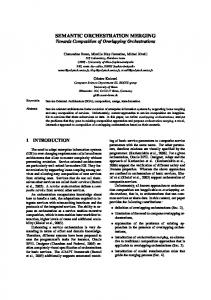
Orch.Regulate.indication which is sent to the orchestrating LLO and thence to the originating HLO. 4.3.2 Orch.Delayed This primitive is issued by the HLO in response to the situation where it can be deduced that an application thread is responsible a connection being behind the required schedule (see section 4.3.1.2). The effect of an Orch.Delayed.request is to cause an indication to be delivered to the application thread(s) causing the delay. The intended interpretation of a Orch.Delayed.indication is that the thread is not running sufficiently fast to produce/ consume data at a rate required by the client of the location independent orchestration service. Applications so informed may take any appropriate action such as requesting more processor resources or dropping OSDUs and should then reply with an Orch.Delayed.response. 4.3.3 Orch.Event This primitive is used to register an interest in a particular application defined event associated with some OSDU; it thus provides support for event-driven synchronisation. To register an interest in some application defined event, a Orch.Event.request is issued which is forwarded to the LLO instance at the sink end of the specified connection, together with a bit pattern representing the event. Subsequently, the sink LLO instance will match this bit pattern, which is not interpreted in any way by the LLO, against the bit patterns in the event fields of the OPDUs associated with incoming OSDUs (see section 5) on the set of orchestrated connections. If the event in the OSDU matches the registered bit pattern, a Orch.Event.indication is raised both locally to the sink application thread and also to the originating HLO via the orchestrating LLO instance. To actually cause an event to be initiated, the event fields of OSDUs may optionally be set by the source application thread when writing an OSDU. An example of use of the event mechanism is when a change of encoding is being signalled in the data stream such as the introduction of a particular compression scheme. It would obviously be possible to implement such a scheme in an ad-hoc manner in the application layer, but this would require that application threads examine each incoming OSDU. The present scheme avoids complicating application code, permits system dependent optimisations to be made, and also permits OSDUs to be dumped directly into, say, a video frame buffer. 5. MODE OF USE We now attempt to place the orchestration services in perspective by illustrating their use in the microscope application scenario of section 2. Note, however, that the LLO services are self contained and could in principle be used by a number of alternative upper layer designs. In the forthcoming description much of the detail of the synchronisation manager and the HLO layers of the architecture is omitted. The main intention is to show how the LLO interface primitives are used in a realistic scenario. Consider an application configuration in the scenario of section 2 where a multimedia document needs to be played back to two separately located scientists who are conferring over a video telephone. The document contains two video clips which view the same sample at different levels of magnification, together with occasional voice annotation and text captions. The various components of the document are separately stored but must nevertheless be synchronised on playout both together and across the two scientist's workstations. The details of the required synchronisation (i.e. timing of text captions, starting time of annotation, degree of permitted slack etc.) are contained in a 'script' encapsulated within the multimedia document structure. Figure 5 illustrates the logical topology associated with this configuration. When it is required to play the document the following sequence of events takes place at the application platform level (see section 3.1). Firstly, the controlling application program obtains
a location independent handle onto the document and passes it to a playout service. The playout service obtains handles on the various media sources in the document, obtains or creates (platform level) playback devices (i.e. video windows, speakers, caption windows) on the required workstations, and connects the sources and sinks together by means of the platform’s connection (stream) abstraction. Once the playout service has performed the necessary platform operations to connect the configuration - which results in the underlying transport connections being established - it begins to parse the script associated with the document.
text audio multimedia document
synchronisation constraints
video 1 video 2
Figure 5: Example topology. When parsing the script, the playout service determines the streams which are to be synchronised and passes their handles to the top level component of the orchestration architecture illustrated in figure 1: i.e. the synchronisation manager. At this time, the playout service also initialises and starts the source and sink devices in the session via RPC. This, however, will not cause data to flow as the flow of data is controlled by the orchestration services. Next the synchronisation manager determines the physical location of the sources and sinks of the streams involved and selects the orchestrating node. It then instantiates an HLO instance on the orchestrating node and passes it details derived from the document script. These details include the ratio of OSDU delivery for each stream to a reference time line, and ‘on’ and ‘off’ events for each stream. For example, the ‘on’ event for a caption or voice annotation could be the delivery of a particular OSDU in a video stream, and the ‘on’ event for the video streams would be the start of the session itself. The first action of the HLO is to create a platform level control interface handle onto itself which it returns to the controlling application. This interface contains start, stop, prime operations which the application can invoke via RPC to control the set of streams as an atomic unit. After this the HLO instantiates the orchestration session by issuing the Orch.request primitive. Subsequently, on receiving prime and start invocations from the application, the HLO issues the Orch.Prime.request and Orch.Start.request primitives which start data flowing in the orchestrated set of connections. The data flow will then be controlled by the HLO by means of the Orch.Regulate primitive according to the document policy. At certain points in the playout, as determined by the script, the HLO will pass caption OSDUs through to the caption window. The event causing this action could be either an explicit OSDU number, or an Orch.Event.indication depending on the contents of the script. If the platform level application wants to momentarily pause the playout, it issues a stop invocation which results in the HLO issuing an Orch.Stop.request and thus freezing the flow of data. Note that as synchronisation is event driven rather than being associated with absolute time, pauses will not affect subsequent caption and voice annotation timings when the playout is restarted. Finally, it is possible to dynamically add new streams to an ongoing session; for example, the scientists may want to run a library video clip along with the current sample. This is
achieved by passing the handle of a new source/stream/sink configuration to the synchronisation manager which derives the physical locations of the sources and sinks and passes them to the HLO. The HLO then issues the Orch.Add.request primitive for the new stream. Subsequently, Orch.Prime, Orch.Start and Orch.Stop will take effect on the new stream in addition to the established session. 6. CONCLUSIONS We have motivated the need for comprehensive real-time synchronisation support in distributed multimedia systems, and have described the low level components of a design which performs synchronisation of continuous information streams in such a system. The low level orchestration services provide a mechanism to group existing transport connections and control the flow of information in these connections according to given synchronisation constraints. Primitives are provided to prime, start and stop the information in the grouped connections as an atomic unit, and also to regulate the rate of flow in each connection with a flexible degree of granularity. Although the system acts mainly on transport connections, primitives are provided which supply hints to end systems when they are running to slow to meet the required end-to-end synchronisation constraints. The low level orchestration services are embedded in a larger design which presents the functionality of the lower layers to applications through a distributed object-based computational model. The orchestration services can be used as a component of a range of possible higher level services including playout services for complex multimedia components with encapsulated synchronisation specifications. In terms of implementation, we currently have the low level orchestration services in place and have also completed the high level application platform. The implementation has been carried out in the context of a collection of standard workstations augmented with transputer based multimedia network interface (MNI) units [16] which handle both network interfacing and all continuous media source and sink mechanisms such as video and audio capture, restitution and storage. The workstations are connected by means of a real-time transputer based emulation of an FDDI network. We use a specially designed rate based transport protocol which provides simplex connections with a high degree of QOS configurability [13]. More details of the implementation can be found in [17]. Finally, our future plans involve the development of the high level orchestrator component which acts as the link between the platform abstractions and the low level orchestration mechanisms. This component is expected to be fairly complex as it is required to simultaneously monitor and control a number of orchestrated connections in real-time according to an arbitrarily application defined specification. However, because of the support provided by the lower layers, the HLO will not have to consider real-time communication and distribution issues as these are delegated to the LLO services. ACKNOWLEDGEMENT Part of this work was carried out within the MNI project (funded under the UK SERC Specially Promoted Programme in Integrated Multiservice Communication Networks (grant number GR/F 03097) and co-sponsored by British Telecom Labs), and part within the OSI 95 project (ESPRIT project 5341, funded by the European Commission). REFERENCES 1 Anderson, D.P., S.Y. Tzou, R. Wahbe, R. Govindan and M. Andrews, "Support for Continuous Media in the DASH System". Proc. of the 10th International Conference on Distributed Computing Systems, Paris, May 1990. 2
Williams, N., G.S., Blair, and R.A. Head, “Multimedia Computing: An Assessment of the State of the Art”, To appear in Journal of Information Services and Use, October 1992.
3
Blair, G.S., F. Garcia, D. Hutchison and W.D. Shepherd. "Towards New Transport Services to Support Distributed Multimedia Applications", Presented at Multimedia '92: 4th IEEE COMSOC International Workshop, Monterey, USA, April 1-4, 1992.
4
Steinmetz, R., "Synchronisation Properties in Multimedia Systems." IEEE Journal on Selected Areas in Communications IEEE JSAC Vol. 8 No. 3, pp 401-412, April 1990.
5
Little, T.D.C., and A. Ghafoor. "Network Considerations for Distributed Multimedia Object Composition and Communication." IEEE Network Magazine, pp 32-49, November 1990.
6
Hazard, L., F. Horn, and J.B. Stefani. "Notes on Architectural Support for Distributed Multimedia Applications", CNET/RC.W01.LHFH.001, Centre National d'Etudes des Telecommunications, Paris, France, March 91.
7
Williams, N., and G.S. Blair "A Distributed Multimedia Application Study" To appear in Computer Communications, 1992, and available as an Internal Report, Computing Department, Lancaster University, Bailrigg, Lancaster LA1 4YR, UK, June 1991.
8
Lougher, P. "The Design of a Multimedia Storage Server", Internal Report. Computing Department, Lancaster University, Bailrigg, Lancaster LA1 4YR, UK. April 1991.
9
Tennenhouse, D.L., "Layered Multiplexing Considered Harmful", Protocols for HighSpeed Networks, Elsevier Science Publishers B.V. (North-Holland), 1990.
10 Coulson, G., G.S. Blair, N. Davies, and N. Williams, “Extensions to ANSA for Multimedia Computing”, Computer Networks and ISDN Systems, 25, pp 305-323, 1992. 1 1 APM Ltd. "The ANSA Reference Manual Release 01.01", Architecture Projects Management Ltd., Poseidon House, Castle Park, Cambridge, UK, July 1989. 1 2 Blair, G.S., and G. Coulson. "Meeting the Real-time Synchronisation Requirements of Multimedia in Open Distributed Systems", Internal Report, Computing Department, Lancaster University, Bailrigg, Lancaster LA1 4YR, UK. 1 3 Shepherd, W.D., D. Hutchison, F. Garcia and G. Coulson. "Protocol Support for Distributed Multimedia Applications." Second International Workshop on Network and Operating System Support for Digital Audio and Video, IBM ENC, Heidelberg, Germany, Nov 18-19 1991. 1 4 Mills, D.L., "Internet Time Synchronisation: the Network Time Protocol", Internet Request for Comments No. 1129 RFC-1129, October 1989. 1 5 Bernstein, P.A., and N. Goodman. "Concurrency Control in Distributed Database Systems." Computing Surveys Vol 13 No. 2, pp 185-221, June 1981. 1 6 Ball, F., D. Hutchison, A.C. Scott, and W.D. Shepherd. "A Multimedia Network Interface." 3rd IEEE COMSOC International Multimedia Workshop (Multimedia '90), Bordeaux, France, Nov 1990. 1 7 Davies, N., G. Coulson, N. Williams, and G.S. Blair. "Experiences of Handling Multimedia in Distributed Open Systems", Presented at SEDMS '92, Newport Beach CA, April 1992; also available from Computing Department, Lancaster University, Bailrigg, Lancaster LA1 4YR, UK. November 1991.