OTuA4.pdf
Orthogonal-Frequency-Division Multiplexing for Optical Dispersion Compensation Arthur James Lowery and Jean Armstrong Department of Electrical & Computer Systems Engineering, Monash University, Clayton, 3800, Australia Tel: +61 3 9905 3223, Fax: +61 3 9905 3454,
[email protected]
Abstract: Orthogonal Frequency Division Multiplexing offers an attractive method of electronically compensating for single-mode and multipath dispersion in optical links and optically-switched networks. This paper reviews recent progress in optical OFDM systems. ©2007 Optical Society of America
OCIS codes: (060.2330) Fiber optics communications (060.4080) Modulation
1. Introduction Orthogonal-Frequency Division Multiplexing (OFDM) has been widely adopted in RF-wireless systems such as cell-networks, digital-audio broadcasting and digital-video broadcasting [1] because it efficiently compensates for multipath dispersion. Equalization is performed at the receiver, so that variations in dispersion along the path can be followed by the equalizer. This ability of OFDM to equalize broadcast systems is of particular merit for all-optical networks, where network switching including protection switching means the exact path across the network cannot be predetermined. In contrast, optical dispersion compensation using electronic precompensation [2], [3] has difficulty operating with switched networks, as the propagation path has to be known before signal transmission. Given OFDM’s dominance of radio systems, why hasn’t OFDM been adopted in optical systems, and what is required for ‘optical’ OFDM to become a contender for dispersion compensation? This paper seeks to answer these questions and presents the latest work on optical OFDM. For those unfamiliar with OFDM technology, it first reviews how OFDM works in an electrical system. The issues with applying bipolar (electrical) signals to unipolar (optical amplitude) signals are solved, then the signal processing requirements discussed.
Parallel to Serial
2N
N
Demodulation
fRF
Equalization
Q fRF
N
Q RF Channel
Transmitter
I IQ Dem.
FFT
IQ Mod.
ADC ADC
I
Bipolar OFDM Signal
Serial to Parallel
DAC DAC
Parallel to Serial
N
IFFT N
Modulation
2N
Data
Serial to Parallel
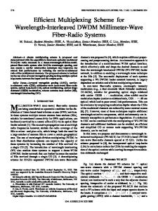
2. Orthogonal Frequency Division Multiplexing As its name suggests, OFDM uses frequency division multiplexing to transmit data. That is, data is transmitted over many (say, N) parallel frequencies (subcarriers), each with a baud rate of 1/(N.log2m) of the total data rate, where m is the order of the m-QAM modulation of each subcarrier. Thus, individually, each sub-carrier should be more tolerant to propagation effects: for chromatic dispersion in an optical fiber, the dispersion limit is inversely proportional to the square of the baud rate, B, so using N subcarriers will increase the dispersion limit by (N.log2m)2. Using many low-data rate optical subcarriers to mitigate optical dispersion is not new [4]; however, OFDM takes advantage of digital signal processing of fast-Fourier transforms (FFTs) to achieve high sub-carrier density (N) and efficient phase and amplitude equalization. The ‘orthogonal’ in OFDM is a result of how the subcarriers are encoded, received and processed as blocks (also known as symbols in conventional OFDM): each block representing a portion Tblock of the signal’s waveform. It is helpful to consider the receiver first. As illustrated in Fig. 1 (right), the receiver digitizes the incoming waveform, then presents each block to a Fast Fourier Transform (FFT). The FFT extracts the phase and amplitude of each subcarrier. If the subcarriers were arranged to have periods of Tblock/n, where n is an integer, then they will be orthogonal in frequency space, and the FFT will be able to separate the subcarriers perfectly with no crosstalk.
Receiver
Fig. 1. Electrical OFDM transmitter (Left) and receiver (right) block diagrams for 4-QAM modulation.
©OSA 1-55752-830-6
Authorized licensed use limited to: Monash University. Downloaded on October 15, 2009 at 22:23 from IEEE Xplore. Restrictions apply.
Data
OTuA4.pdf
The transmitter’s purpose is simple: to create a waveform that is the superposition of the waveforms of all of the subcarriers. This can be achieved by dividing the incoming data into parallel channels, encoding the data using a format such as Quadrature-Amplitude Modulation (QAM), then presenting the modulated channels to an inverse FFT (IFFT). The IFFT generates each sub-carrier with phase and amplitudes defined by the QAM modulators and superimposes them: this could also be achieved using N RF modulators fed by N RF oscillators and an N-input power combiner, but N would be limited by space and electrical performance. Providing that the propagation path is dispersionless, such a system would work perfectly, as the subcarriers would arrive at the receiver without time-shifts, so the received data block would be identical to the transmitted block, and therefore the outputs of the receiver’s FFT would be identical to the inputs of the transmitter’s IFFT. The receiver would just require a bank of QAM demodulators and a serial-parallel converter to recover the original data. However, the purpose of OFDM is to compensate for dispersion, and dispersion will cause time-spreading of the transmitted signals out of the received data block. To maintain orthogonality of the subcarriers, one solution is to add a cyclic prefix to each block [1]. This simply adds a copy of the signal at the end of the block to the beginning of the block. The elegance of this solution is that if the subcarriers are time-shifted relative to one another by less than the duration of the cyclic prefix, there will be a portion of the received signal waveform that is identical to the original block (before the prefix was added); the subcarriers will be orthogonal within this portion, so there will be no interchannel interference. The cyclic prefix comes at a cost: the rate at which blocks can be transmitted must be reduced to accommodate the extra time required to transmit the prefix of each block. The percentage reduction in data rate depends on the relative durations of the prefix and the blocks themselves; obviously using longer blocks reduces the overhead required to transmit the prefixes. Apart from shifting subcarriers in time, dispersion along the propagation path will also shift the relative phases of the subcarriers, and may also affect their amplitudes if multiple paths exist. OFDM offers an efficient method of dispersion equalization, known as a ‘1-tap equalizer’ [1]. The FFT presents each sub-carrier to the equalizer as a complex number per sub-carrier. The equalizer performs a single complex multiplication to real-imaginary pairs to equalize its phase and amplitude. This of course requires knowledge of the equalization to be applied; this knowledge can be attained using pilot tones or training sequences, for example. In the case of fiber dispersion, the phase response will be quadratic, so could be estimated from three or more pilot tones transmitted on a few of the subcarriers. After equalization, a bank of demodulators recovers the data. For 4-QAM, this means applying thresholds to the real and imaginary parts of the signal to obtain pairs of data bits. 3. Applying OFDM to Optical Signals Electrical OFDM signals are usually bipolar – containing both positive and negative peaks. It is possible to modulate an RF OFDM signal onto an optical carrier provided a sufficient bias is added to the electrical OFDM signal to ensure that negative peaks become positive optical powers [5]-[9]. This technique imposes a receiver sensitivity penalty as it requires high mean optical powers compared to the signal content. Typically the receiver sensitivity (the required optical power for a given bit rate) will be degraded by over 6 dB compared with non-return to zero modulation. We have previously demonstrated two solutions to this problem, which are compared in [10]: • Remove all excursions below the mean level of the electrical OFDM signal when converting to an optical OFDM signal. This is called ‘Asymmetrically-Clipped Optical OFDM’ [11]-[13]. As expected from simple Fourier theory, ACO-OFDM causes distortion of the OFDM signals, giving rise to distortion products. However, we have shown that if only odd-frequencies are used, the distortion falls only even frequencies of the OFDM sub-carrier grid [11] so can be completely rejected at the receiver. Alternatively, we can upconvert the OFDM spectrum (of bandwidth C) by a frequency C, so that the lowest frequency is >C; this gives some inband ‘clipping noise’ on the received subcarriers, but the signal quality per unit optical power is improved [12]: We have shown analytically [11] and by simulations [12] that the receiver sensitivity to be 1.8 dB better than NRZ. • Optically modulate using a strong bias then suppress the optical carrier using an optical filter [14]. This also introduces clipping noise due to intermixing of the subcarriers upon photodetection. The solution is again to upconvert the OFDM band. A variation is to completely remove the optical carrier at the transmitter and reintroduce it at the receiver [16], but this requires a ‘coherent’ receiver design which should be insensitive to polarization. In both systems it is desirable to suppress one optical sideband so that fiber dispersion does not cause strong nulls in the baseband spectrum after photodetection [17]. 4. Fiber Nonlinearity Because Optical OFDM uses tens to hundreds of closely-spaced optical carriers, one expectation might be that fiber nonlinearity will cause strong Four-Wave Mixing (FWM) between the many OFDM subcarriers, limiting the optical signal power, thus lowering the Optical Signal to Noise Ratio (OSNR) in a long-haul system. At OFC 2006 we
©OSA 1-55752-830-6
Authorized licensed use limited to: Monash University. Downloaded on October 15, 2009 at 22:23 from IEEE Xplore. Restrictions apply.
OTuA4.pdf
presented extensive simulations [15] of the effect of fiber nonlinearity, and showed that the although FWM is not eliminated due to fiber dispersion, it is low enough to allow transmission across 4000 km with 80-km optical amplifier spans in a 32-channel WDM system carrying 320-Gbit/s. More recently we have investigated the effects of WDM channel spacing, fiber dispersion, and number of WDM channels on the nonlinear performance [18]. Djordjevic and Vasic have also studied nonlinearities by simulation [19]. 5. Implementation Issues Optical OFDM requires fast digital signal processing and fast digital-analog and analog-digital conversion. The signal processing task is dependent on the number of subcarriers because of the size of the FFTs. Using a few subcarriers becomes inefficient for highly dispersive links, because of the overhead of the cyclic prefix. However, a 4000-km standard-SMF link with 10 Gbit/s/wavelength has only a 1.5% overhead with 1024-bit FFTs. For 4-QAM signals, the DACs need to operate at 5-Gbit/s if separate DACs are used for I and Q channels and an RF up-converter is used after the DACs, which is a common situation in RF OFDM. At the receiver, analog-digital converters are required to operate at similar rates. Fortunately, OFDM does not require oversampling, as is common with other electronic dispersion-compensation systems, including MLSE [20]. 6. Conclusions OFDM equalizes at the receiver and so can compensate for fixed or time-varying transmission paths. It will work for multiple drop points along the path. This is a great advantage over electronic precompensation, particularly for alloptical networks. If single-sideband transmission is employed, optical-OFDM can potentially compensate for 1000’s of km of fiber dispersion, which far exceeds MLSE techniques. Optical-OFDM is also a scalable technology: increasing the bit rate to 40 Gbit/s only requires a 6-fold increase in processing power for the same overhead. References [1] J.G. Proakis and M. Salehi, Essentials of Communications Systems Engineering (Prentice Hall, New Jersey, 2005) [2] J. McNicol, M. O’Sullivan, K. Roberts, A. Comeau, D. McGhan and L. Strawczynski, “Electrical domain compensation of optical dispersion,” Optical Fiber Communication Conference, 2005. Tech. Digest. OFC/NFOEC 4, March 6-11, 269 – 271 (2005). [3] R.I. Killey, P.M. Watts, V. Mikhailov, M. Glick, and P. Bayval, “Electronic dispersion compensation by signal predistortion using digital processing and a dual-drive Mach-Zehnder modulator,” IEEE Photon. Technol. Letts. 17, 714-716 (2005) [4] R. Hui, B. Zhu, R. Huang, C.T. Allen, K.R. Demarest and D. Richards, “Subcarrier multiplexing for high-speed optical transmission,” J. Lightwave Technol. 20, pp. 417-427 (2002). [5] M. R. D. Rodrigues and J. J. O’Reilly, “Assessment of the performance of radio over fibre based wireless networks employing OFDM signalling,” Proceedings of the London Communications Symposium 1999, London, U.K., pp. 47-50, (July 1999) [6] B.J. Dixon, R.D. Pollard and S. Iezekeil, “Orthogonal frequency-division multiplexing in wireless communication systems with multimode fiber feeds,” IEEE Trans. Microwave Theory and Techniques 49, 1404-1409 (2001). [7] O. González, R. Pérez-Jiménez, S. Rodríguez, J. Rabadán and A. Ayala, “OFDM over indoor wireless optical channel,” IEEE Proc. – Optoelectron. 152, 199-204 (2005). [8] D. Chanda, A.B. Sesay and Bob Davis, “Performance of clipped OFDM signal in fiber,” Proc. IEEE Canadian Conference on Electrical and Computer Engineering 4, 2401-2404 (IEEE, N.Y., 2004). [9] J.M. Tang, and K.A. Shore, “30-gb/s signal transmission over 40-km directly modulated DFB-laser-based single-mode-fiber links without optical amplification and dispersion compensation,” J. Lightwave Technology, 24, 2318-2327 (2006). [10] A. J. Lowery and J. Armstrong, “Comparison of power-efficient optical orthogonal frequency division multiplexing transmission methods”, Proceedings of the Australian Conference on Optical Fiber Communications, ACOFT (2006). [11] J. Armstrong and A. J. Lowery, “Power efficient optical OFDM,” Electronics Letters 42 (6), 370-371 (March 16, 2006). [12] A. J. Lowery and J. Armstrong, “10 Gbit/s Multimode fiber link using power-efficient orthogonal-frequency-division multiplexing,” Opt. Express 13, 10003-10009 (2005). [13] J. Armstrong, B. J. C. Schmidt, D. Kalra, H. A. Suraweera, and A. J. Lowery, “Performance of asymmetrically clipped optical OFDM in AWGN for an intensity modulated direct detection system,” presented at IEEE Globecom 2006, San Francisco, 2006. [14] A. J. Lowery and J. Armstrong, “Orthogonal frequency division multiplexing for dispersion compensation of long-haul optical systems”, Opt. Express 14, 2079-2084 (2006). [15] A. J. Lowery, Liang Du and J. Armstrong, “Orthogonal frequency division multiplexing for adaptive dispersion compensation in long haul WDM systems”, in Tech. Digest of the Conference on Optical Fiber Communication, (Optical Society of America, 2006), Postdeadline PDP39. [16] W. Shieh and C. Athaudage, “Coherent optical orthogonal frequency division multiplexing,” Electronics Letters 42, 587-588 (2006). [17] M. Sieben, J. Conradi and D.E. Dodds, “Optical single sideband transmission at 10 Gb/s using only electrical dispersion compensation,” J. Lightwave Technol. 17, 1742-1749 (1999). [18] A. J. Lowery, Liang Du and J. Armstrong, “Performance of optical OFDM in ultra long-haul WDM lightwave systems”, submitted to J. Lightwave Technology, June 2006. [19] I. B. Djordjevic and B. Vasic, “Orthogonal frequency division multiplexing for high-speed optical transmission,” Opt. Express 14, 37673775 (2006). [20] T. Kupfer and C. Schulien, “Maximum likelihood sequence estimation at 10 Gb/s from concept to implementation,” in Proceedings of the Lasers and Electro-Optics Society Annual Meeting, (IEEE, 2005), pp. 896-897.
©OSA 1-55752-830-6
Authorized licensed use limited to: Monash University. Downloaded on October 15, 2009 at 22:23 from IEEE Xplore. Restrictions apply.