IEEE PHOTONICS TECHNOLOGY LETTERS, VOL. 19, NO. 24, DECEMBER 15, 2007
2015
Orthogonal Wavelength-Division Multiplexing Using Coherent Detection Gilad Goldfarb, Guifang Li, and Michael G. Taylor, Member, IEEE
Abstract—Optical wavelength-division multiplexing (WDM) with channel spacing equal to the symbol rate is demonstrated. Coherent detection with subsequent digital signal processing is used for demultiplexing and demodulation. Experimental results for a 6-Gbaud binary phase-shift keying WDM transmission with a 6-GHz channel spacing achieve a -factor penalty of 2.8 dB compared to a single-channel transmission. Index Terms—Coherent detection, digital signal processing (DSP), optical fiber communication, wavelength-division multiplexing (WDM).
II. SYSTEM MODEL The experiment and simulations described in this letter are for the single-polarization binary phase-shift-keyed (BPSK) transmission format, with all WDM channels copolarized. A higher data rate would be obtained using quadrature PSK and polarization-division multiplexing, but the impact of crosstalk should be about the same as for single-polarization BPSK. A model of the communication system considered is described as follows. The electric field of the transmitted optical signal is given as
I. INTRODUCTION (1)
H
IGH-SPEED digital signal processing (DSP) is emerging as a complementary technology to coherent detection for optical transmission systems. DSP alleviates the need for phase tracking using a phase-locked-loop and allows mitigation of various impairments in the digital domain [1]. Coherent detection achieves higher sensitivity and longer transmission reach compared to direct detection. Another advantage of coherent detection often quoted is the inherent ultranarrow optical filtering capability, because optical filtering is effectively performed in the electrical domain. A wavelength-division-multiplexing (WDM) channel spacing of 1.3 times the symbol rate has been demonstrated, with a penalty of over 10 dB [2]. The penalty monotonically increased with decreasing channel spacing in that experiment. In principle, it is possible to have a WDM channel spacing equal to the symbol rate with no penalty. Orthogonal frequency-division multiplexing (OFDM) is known to achieve this condition, but arranging for the WDM channels to be orthogonal relative to one another would require too much bandwidth at the transmitter and receiver to be implemented. In this letter, the case is investigated theoretically and experimentally where the channel spectra are allowed to overlap, but realistic pulse shapes are used. We call this condition orthogonal WDM (OWDM). A modest penalty of 2.8 dB is obtained experimentally when the channel spacing is equal to the symbol rate using OWDM. Manuscript received June 16, 2007; revised August 24, 2007. This work was supported in part by Defense Advanced Research Projects Agency (DARPA) under Contract DAAD1702C0097. G. Goldfarb and G. Li with the College of Optics and Photonics: CREOL & FPCE, University of Central Florida, Orlando, FL 32816-2700 USA (e-mail:
[email protected];
[email protected]). M. G. Taylor is with the College of Optics and Photonics: CREOL & FPCE, University of Central Florida, Orlando, FL 32816-2700 USA, and also with Atlantic Sciences, Laurel, MD 20725-0306 USA. Color versions of one or more of the figures in this letter are available online at http://ieeexplore.ieee.org. Digital Object Identifier 10.1109/LPT.2007.909895
where and are the total number of optical channels, pulse shape, symbol rate, and angular carrier frequency of is the th information symbol the th channel, respectively. are seof the th channel, and for BPSK, the values of the lected from . At the coherent receiver, the transmitted (exsignal is mixed with the local oscillator (LO). Noise pressed in baseband) is added to the signal by the communications channel, and then it is detected by a coherent receiver. The output signal from the receiver is (2) where is the net receiver impulse response, composed of the impulse response of the receiver front end combined with additional equalization filtering. When the coherent receiver is like that of [1] the receiver output is in digital form, and postdetection equalization is implemented by a digital filter, but it is assumed that the sampling rate is high enough that and can be considered. continuous time functions refers to the effective LO frequency, given by the actual LO frequency together with any adjustment applied in the digital domain. In general, reducing channel spacing in a WDM system is expected to lead to increased penalty due crosstalk where the spectra of adjacent channels starts to overlap. However, if the channel spacing and transmit and receive pulse shapes are such that adjacent channels are orthogonal to each other, this penalty can be cancelled even though the adjacent channel spectra is a perfectly still overlap. For OFDM, the pulse shape is the same square pulse square pulse (of width ) and (the matched filter). In this case, there is no crosstalk from the adjacent channels. To illustrate this principle, (1) and (2) are
1041-1135/$25.00 © 2007 IEEE
2016
IEEE PHOTONICS TECHNOLOGY LETTERS, VOL. 19, NO. 24, DECEMBER 15, 2007
Fig. 2. Experimental setup. Fig. 1. Eye-diagram simulation. Single channel (left); two OFDM channels (right).
written for two channels spaced by
, where
Fig. 3.
(3) The second channel is extinguished by convolution with the is a triangular pulse shape. Note that the data receive filter. streams of the two channels must be aligned in time, otherwise within the integraany change in the information carried by from tion period would prevent the term canceling. It is not usual to align the symbol periods of WDM channels, but such a feature might be considered worth introducing to obtain very high information spectral density. Simulation of the eye diagram for the two-channel system (for 6-Gbaud BPSK) is presented in Fig. 1. The carrier phase of Channel 2 was slowly ramped so that all phases were explored. This leads to the filled out appearance of the Channel 1 eye, but notice that the phase does not affect the perfect crosstalk cancellation at the eye center. The average interchannel crosstalk of this OFDM case is high, 8.3 dB, which can be thought of as the average crosstalk over a whole symbol period or as the amount of overlap of the spectra of the two channels. The symbol intervals of the two channels are perfectly aligned in the simulation of Fig. 1(b). A small misalignment would clearly result in a substantial crosstalk penalty at the symbol center. The principle illustrated above is referred to as OFDM. However, the square pulse condition cannot be met for the high symbol rates used in fiber-optic transmission as it would require too much transmitter and receiver bandwidth. Orthogonal WDM aims for the narrow channel spacing without the requirement of perfectly square pulse shapes. This may lead to a penalty when the channel spacing is equal to the symbol rate. A mode of OFDM that has been proposed recently for optical communications is where closely spaced digital subcarriers are generated within each WDM channel, carrying information having very long pulse duration. This OFDM realization is
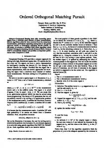
Q-factor versus channel spacing.
efficient in mitigating intersymbol interference due to fiber dispersion effects [3]–[5]. However, it is not clear that this method allows WDM channels to be spaced any more closely than with conventional WDM channels using direct detection. An additional advantage of the OWDM scheme suggested in this letter is that it allows tight WDM channel spacing while the transmitter employs simple binary modulation. III. EXPERIMENTAL RESULTS To verify the viability of the suggested OWDM scheme, an experiment was performed as presented in Fig. 2. The center is BPSK-modulated using a Mach–Zehnder modchannel ulator driven at 6 Gbaud by a pattern generator. Pseudorandom was used. Two adjacent chanbit sequence of length and ) are also modulated and combined with the nels ( center channel. Note that the adjacent channels have synchronized symbol times but decorrelated data content compared to the center channel. Noise is loaded by combining the three modulated channels with the output of several cascaded erbiumdoped fiber amplifiers (EDFAs) with no input, inducing amplified spontaneous emission (ASE). A 90 hybrid and real-time oscilloscope (RTO) are used to coherently detect and sample . the noise-loaded signal. The LO frequency was set to match The obtained samples were processed offline. The ASE level was set so the decision-threshold -factor in the absence of adjacent channels was approximately 14 dB. An adaptive equalization algorithm was employed to obtain a filter which maximizes the -factor in the absence of adjacent channels. This filter was used in subsequent measurements. To determine the channel crosstalk penalty, the channel spacing and and the -factor measured was scanned by varying symbols were used to determine the for each case. performance for each channel spacing. The decision-threshold
GOLDFARB et al.: OWDM USING COHERENT DETECTION
2017
Fig. 5. Simulation of 10-Gbaud center channel eye, without (left) and with (right) an AA-filter.
Fig. 4. Simulation (top) and experimental (bottom) eye diagrams for single channel (left) and with adjacent channels spaced at 6 GHz (right).
-factor for each channel spacing is shown in Fig. 3. When the channel spacing is much tighter than the symbol rate, a large penalty is incurred. This penalty is reduced as the channel spacing grows, up to an optimal point (7.5 GHz for OWDM, compared to 6 GHz for OFDM). This shift in optimum channel spacing to a higher value than the symbol rate is due to asymmetries in the pulse shape. Increasing the channel spacing even further actually increases the penalty. From a certain channel spacing onward, the channels are spaced enough so that the spectral overlap is diminished and the -factor levels off. It is seen that the best result is obtained for a channel spacing of 7.5 GHz (penalty of 0.15 dB), while at the symbol rate (6 GHz) the penalty is 2.8 dB. Also shown in Fig. 3 are the simulation results when three and five WDM channels are present. There is a slight penalty (0.8 dB) when five channels are considered which arises because the next-to-nearest neighbors have a small spectral overlap with the center channel. Simulations show slightly lower optimum channel spacing than the experiment, probably because the actual pulse shape deviates from raised cosine shape assumed for the simulations. Simulated (top) and experimental (bottom) eye diagrams without crosstalk (single channel, left) and with two adjacent channels separated by 6 GHz (right) are presented in Fig. 4. Crosstalk is suppressed at the center of the eye with adjacent channels. The simulation assumes a raised cosine shaped transmit pulse and receiver impulse response, with roll-off factor 0.3. The OWDM eye diagram with adjacent channels shows that the crosstalk is lower (but not zero) at the center of the symbol compared to the average over the whole symbol. The OWDM simulation indicates the average crosstalk is 8.9 dB, while the symbol center crosstalk is 16.0 dB. There is good correspondence between simulation and experiment. IV. CONCLUSION AND DISCUSSION The OWDM channel spacing reported in this letter (i.e., 6 GHz with 6-Gbaud channels) represents, to the best of our knowledge, the highest spectral efficiency and lowest penalty obtained to date for a binary modulation format. The reason
for choosing a 6-GHz symbol rate in the experiment is that it was found to be necessary to use a low symbol rate to avoid a crosstalk penalty associated with the clipping of the optical spectra of the adjacent channels. The RTO front end includes an anti-aliasing (AA) filter with a steep cut-off at 12.5 GHz. This means that although the center channel’s spectrum was detected in full, the two adjacent channels were effectively clipped. The symmetry condition that leads to crosstalk suppression at the center of the symbol requires the entire spectra of the adjacent channels to be present, even though the aim is to suppress the adjacent channels. The AA filter was represented as a tenth-order Butterworth filter in the simulation, and could be switched ON and OFF. Fig. 5 shows the eye diagrams for a simulation of three 10-Gbaud channels separated by 10 GHz, with and without the AA filter. Suppression of the crosstalk at the symbol center compared to the average of the whole symbol is 6.0 dB in the absence of the AA filter, and only 1.9 dB with the filter present. Introducing the AA filter adds a -factor penalty of 2.1 dB. The requirement that the receiver bandwidth be wide enough to see three adjacent WDM channels adds expense to the receiver. In our experiment, a 40-GSa/s digitizer with 12.5-GHz bandwidth was used to detect a 6-Gbaud signal. In the future, one might have several coherent receivers observing neighboring blocks of channels and sharing information between them, so that the electric field envelope of one channel is obtained from digitized samples from two coherent receivers. In that scenario, the requirement for excess sample rate is alleviated, when averaged over all the WDM channels. REFERENCES [1] M. G. Taylor, “Coherent detection method using DSP for demodulation of signal and subsequent equalization of propagation impairments,” IEEE Photon. Technol. Lett., vol. 16, no. 2, pp. 674–676, Feb. 2004. [2] S.-Y. Kim and K. Kikuchi, “1000-km transmission of 20-Gbit/s QPSK-NRZ co-polarized DWDM signals with spectral efficiency of 1 bit/s/Hz using coherent detection,” in Optical Fiber Communication Conf. (OFC 2007), Anaheim, CA, Mar. 25–29, 2007. [3] N. E. Jolley, H. Kee, R. Rickard, J. Tang, and K. Cordina, “Generation and propagation of a 1550 nm 10 Gb/s optical orthogonal frequency division multiplexed signal over a 1000 m of multimode fiber using a directly modulated DFB,” in Proc. OFC/NFOEC, Anaheim, CA, Mar. 11, 2005. [4] A. J. Lowery, L. Du, and J. Armstrong, “Orthogonal frequency division multiplexing for adaptive dispersion compensation in long haul WDM systems,” in Proc. OFC/NFOEC, Anaheim, CA, Mar. 2006, Paper PDP39. [5] W. Shieh, X. Yi, and Y. Tang, “Transmission experiment of multi-gigabit coherent optical OFDM systems over 1000 km SSMF fibre,” Electron. Lett., vol. 43, pp. 183–184, Feb. 2007.