Report, NSF Phase I SBIR Award No. ISI-9160269, 1992. [4] Bowman, L., McEntee, J., Diaphragm Actuator for a Stirling. Microrefrigerator. NASA SBIR 91-1, ...
Oscillating Diaphragms J. McEntee*, L. Bowman** * McEntee Engineering, PO Box 568, Castine, ME 04421, USA ** Sunpower, Inc., PO Box 2625, Athens, OH 45701, USA
ABSTRACT The manufacture of miniature Stirling cycle cryocoolers, using standard micro-machining techniques and materials has been pursued by the authors [1]. A MEMS based cryocooler would allow integration of a cryogenic cooling system directly into a cryoelectronic device. Resonant bossed diaphragms were proposed as the means to sweep the working gas in the Stirling cooler, replacing the pistons and displacers found in macro scale free-piston machines. Analysis of round, bossed diaphragms led to the realization that there exists shape factors by which the swept volume and kinetic energy of any diaphragm can be characterized. Knowledge of the volume swept by a diaphragm allows for the calculation of a potential energy associated with diaphragm deflection. Knowledge of the potential and kinetic energies allows for the design of a diaphragm of known dynamic characteristics operating in a closed gas space with large gas pressure spring and damping effects.
diaphragm diameter. An analogue of the Volume Shape factor was found in the Energy Shape factor, which characterizes the kinetic energy of a moving diaphragm for given diaphragm dimensions. Comparison with finite element models of square bossed diaphragms show that the same factors can be used in the design of square diaphragms. Using shape factors appropriate dimensions for a diaphragm can be chosen, and the resonant frequency in the presence of significant gas pressure can be predicted. Shape factors greatly simplify the design process for resonant diaphragms oscillating in a high pressure gas, and contribute to an understanding of the fundamental behavior of oscillating diaphragms. Circular and square diaphragms were etched, and test results indicated that the theoretically derived shape factors are correct, although difficulties in maintaining uniform diaphragm thickness, as well difficulties in achieving fully fixed edge conditions, weaken the correlation between experimental data and theory.
Keywords: Diaphragms, Stirling, Cryocooler, Dynamics.
ANALYSIS OF FLAT DIAPHRAGMS INTRODUCTION MEMS based Stirling cryocoolers would allow integration of a cryogenic cooling inside a microelectronics package, offering performance and cost benefits. Thermodynamic and fluid dynamic behavior of high frequency Stirling cycle machines have been examined analytically [2] and experimentally [3] and no barrier to the practical implementation of such machines has been found. Resonant bossed diaphragms are proposed as the means to sweep the working gas in the Stirling cooler, replacing the pistons and displacers found in macro scale free-piston machines. In these machines motions are unconstrained by linkages: amplitudes of motion and phase angles are determined by thermodynamic cycle properties and dynamic properties of components. Diaphragm design is constrained by system level parameters, including the requirements for a certain swept volume of working gas, a specific resonant frequency, and a characteristic Q factor [4]. Analysis of round, bossed diaphragms led to the realization that there exists a Volume Shape factor by which the swept volume of any diaphragm can be characterized. This factor is determined by edge conditions and the solidity ratio: the ratio of boss diameter to
Analysis of the static deflection of diaphragms is well documented in the classical plate bending literature. Many researchers have developed small and large deflection analysis for constant thickness plates [5].
Volume Displaced by Diaphragms Using standard assumptions of linear behavior the deflection of a fixed edge, constant thickness diaphragm loaded by transverse pressure is given by
y
3. P. 1
2
ν . 2 a
3 16. E. h
2 2
r
{1}
where y is the deflection at radius r, under applied pressure P, for a diaphragm of radius a, thickness h, Young’s Modulus E, and ν. The maximum deflection of the diaphragm which occurs at the center (r = 0) is
y0
3. 1
2 4 ν . P. a
3 16. E. h
{2}
By integration of Equation 1 the volume swept by a moving diaphragm is found 6 2 3. π . P. a V 1 ν . 3 48. E. h {3} Substituting Equation 2 into 3 we find that the swept volume of the diaphragm is related to the maximum deflection and the diaphragm area. π .a y 0
2 K. π . a . y 0
{4(b)}
Kinetic Energy of Diaphragms To understand the dynamic response of a diaphragm it is critical that the kinetic and potential energy characteristics of the diaphragm be recognized. Kinetic energy of the diaphragm can be determined in much the same manner as swept volume. For a diaphragm oscillating at fixed radial frequency ω, with a deflection profile equal to the static deflection profile, integration will lead to a kinetic energy T, for the diaphragm. 2
ω . 2
2
y dm
2
T
ρ. h. π . ω
which can be further rearranged to give a general form 1 . . . 2. mω y0 F 2
where F is the Energy Shape Factor for the diaphragm. The factor F relates the kinetic energy of the diaphragm to total diaphragm mass and to maximum deflection. There exists an energy shape factor F for every configuration of diaphragm, and the value of F depends on the deflected profile of the diaphragm. For a circular, constant thickness diaphragm with small deflections the energy shape factor F is 1/5.
Potential Energy of an Oscillating Diaphragm For a diaphragm oscillating in a gas space with significant gas pressure variations the potential energy comprises two components. The first is the potential energy associated with the mechanical energy stored in the deflected diaphragm. Second is the potential energy stored in the compressed gas in the working chamber. The potential energy of a spring is the product of force and the distance through which the force acts. The work done by a diaphragm as the diaphragm moves through a quarter cycle compressing the working gas is also given by the product of force and the distance through which the force acts. However this work contains both the potential energy of the diaphragm and one quarter of the power dissipated (D/4) in the thermodynamic cycle being implemented. Knowing the system cycle requirements we can determine the pressures which a diaphragm must generate, and the work required per cycle (D). π
( 2. π . r ) . ( ρ . h ) . y dr
2. a
2
10
. . 3 1
2 ν .P
3 16. E. h
U gas
4
D 4
P. area dy 0
{8}
where Ugas is the potential energy of the compressed gas, D is the work per cycle done on the gas by the diaphragm, P is the pressure against which the diaphragm acts, and y is the deflection of the diaphragm. Knowing the deflection profile of the diaphragm (Equation 1) and knowing that the pressure, P, in the work space takes the form
2
which on integration gives
T
2
10
{5}
where ωy is the speed of mass increment dm. For a circular diaphragm of constant thickness the kinetic energy is ω . 2
ω .y 0
{4(a)}
A constant of proportionality K, the Volume Shape Factor, relates the volume swept by a moving diaphragm to area and maximum deflection, and is a geometric property of the deflected diaphragm shape. For the case above, a constant thickness fixed edge diaphragm with small deflections, the K factor equals 1/3. For other diaphragm shapes, the volume shape factor is different, reflecting the differences in the deflection profile. This volume shape factor allows the volume displacing behavior of a diaphragm to be characterized in a straightforward manner.
T
2 ρ. h. a .
{7}
3 V
T
T
2.
V
Rearranging Equation 6 in terms of maximum deflection y0 leads to a simplified form for kinetic energy
2
P {6}
P c. sin( ω . t
φ)
where Pc is the amplitude of the pressure swing and φ is the phase angle of P relative to deflection y, the sum of gas space potential energy and one quarter of the cyclic work is
U gas
6 2. π . P c. a 3. 1 ν 2 . P cos( φ ) . . 3 6 2 . . 16 E h
D 4
π . sin( φ ) 4
to resonate the diaphragm at the machine operating condition. Adding a central boss to the diaphragms was found to be an effective way to increase kinetic energy of the moving diaphragm. The preceding analysis which shows the existence of energy and volume shape factors was adapted for bossed diaphragms.
{9(a)} Substituting for the swept volume (Equation 4(a)) considerably simplifies Equation 9(a), giving V. P c. cos( φ ) 2
4
π. 2
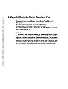
Figure 1: Geometry of circular bossed diaphragms. P c. sin( φ )
{9(b))
Now it is clear that the work done per cycle is D
π . P c. V. sin( φ )
{10}
So the gas space potential energy is simply U gas
V. . P c cos( φ ) 2
To calculate the potential energy due to the spring effect of the diaphragm itself we simply must realize that a pressure P required to deflect a diaphragm is a direct measure of the spring stiffness of the diaphragm. Thus the potential energy contribution from the diaphragm is U diaphragm
V. P 2
V. . P c cos( φ ) 2
1.6 1.4 1.2 1 0.8 0.6 0.4 0.2 0 0
0.2
h2/h1 = 20 {12}
h2/h1 = 4
0.4
0.6
b/a Ratio h2/h1 = 10
0.8
1
h2/h1 = 6
h2/h1 = 2
Figure 2: Energy shape factor/ volume shape factor for boss diameter to diaphragm diameter (b/a) ratios and boss thickness to diaphragm thickness (h2/h1) ratios
and the total potential energy, U, is U
1.8
{11}
where V is the volume swept by the diaphragm, Pc is the pressure amplitude in the working space and φ is the phase angle between pressure swing and diaphragm amplitude.
V. P 2
To analyze a circular diaphragm with a thick central section it is necessary to separate the diaphragm into two separate plates of differing thickness. Bending moments and shear forces are transmitted between plates and lateral and angular deflections are equal at the junction. The use of these compatibility conditions and of plate bending equations [6] allows for the solution of the deflection profile for a bossed diaphragm, and volume and energy shape factors can be determined as before.
Energy Shape Factor/ Volume Shape Factor
U gas
D
{13}
where Pc is the working space gas pressure amplitude and P is the pressure required to deflect the diaphragm through swept volume V.
ANALYSIS OF BOSSED DIAPHRAGMS In the initial design of a micro-refrigerator diaphragm it was clear that flat diaphragms did not have a sufficiently high kinetic energy
To generate the greatest kinetic energy contribution from a diaphragm for a given swept volume the largest ratio of energy shape factor to volume shape factor is desired. Figure 2 shows this ratio as a function of solidity ratio and of boss to diaphragm thickness ratio. As the boss becomes thicker and stiffer the volume shape factor tends towards a limit for a given solidity ratio (b/a). The energy shape factor continues to increase reflecting the larger mass associated with a thicker boss. From Figure 2 it is clear that for increasing boss thickness the maximum energy to volume shape factor ratio occurs at decreasing values of b/a. Thus an optimum diaphragm for our conditions has a small but thick boss.
Finite element models of round bossed diaphragm have confirmed the results presented in Figure 2. Finite element models of square bossed diaphragms and bossed diaphragms of rhomboidal aspect show that their volume and energy shape factors closely follow those of the circular diaphragm that could be inscribed in each respective shape. Volume shape factors for square diaphragms are within +/- 4% of those for circular diaphragms, while those for rhomboidal diaphragms are within +/- 7%. Energy shape factors for square diaphragms are under-predicted by between 3% to 12%, while those for rhomboidal diaphragms are over-predicted by no more than 10%.
Diaphragm Design Procedure Functional requirements of a micro-refrigerator diaphragm dictate the design. A given volume of gas must be moved against a specified gas pressure at a preset oscillation frequency. Assuming a given solidity ratio a set of three simultaneous equations with four unknowns can be constructed from previous arguments. A given amplitude of vibration is determined from Equation 2; a given swept volume of gas is specified by Equation 4(b); setting kinetic energy equal to potential energy by setting Equation 7 equal to Equation 13 defines a resonance condition. A final equation is required for closure. We relate diaphragm thickness to maximum deflection in order to control the degree of non-linear deflection experienced by the diaphragm. y0
z. h 1
{14}
where z is a factor less than 0.3 for linear behavior. Solving these equations results in a functional diaphragm design.
EXPERIMENTAL VERIFICATION Silicon circular bossed diaphragms were isotropically etched giving twelve independent diaphragm designs with differing b/a and h2/h1 ratios. Static deflection and dynamic resonance tests were carried out. Static testing indicated that diaphragms were less stiff than theory would suggest. This is explained by considering the edge conditions imposed on the diaphragm. The theory assumes a fully restrained edge but it is difficult to replicate such a boundary condition under experimental conditions due to the thinness of the silicon wafer which provides the edge support for the diaphragm. In addition there were significant thickness variations across the diaphragm due to processing difficulties. These factors combined to cause deviation of the experimental results from theory. A simple, diaphragm specific, empirical factor was used to correct the theory to match the experimentally measured static behavior. Diaphragm resonant frequencies were measured. After modifying the stiffness of the diaphragm using the empirical factor found by
static testing the predicted resonance frequency matched the experimental values well. Eighteen square and rectangular bossed diaphragms were manufactured by anisotropic etching. These were tested to evaluate static and dynamic behavior. Again the edge conditions contributed to a reduction in diaphragm stiffness, but again the discrepancy between theory and experiment could be corrected by an empirical factor. Resonant frequencies were accurately predicted by theory after edge compliance was accounted for. Attempts were made to analytically predict the degree of edge compliance, but variations in diaphragm mounting made it difficult to correlate empirical stiffness factors with theory.
CONCLUSIONS A method of predicting the dynamic performance of bossed diaphragms has been developed which provides insights on the fundamental parameters that determine such performance. The use of energy and shape volume factors expedited the design process, generating acceptable piston diaphragm designs with a minimal of time consuming numerical analysis. Experimental measurements on circular and square bossed diaphragms verified the fundamental theory for static and dynamic behavior, but exposed the need to properly account for the actual edge conditions applied by the diaphragm mounting.
REFERENCES [1] US Patent 05749226, Microminiature stirling cycle cryocoolers and engines, Bowman L., McEntee J. [2] Bowman, L. A Stirling Micro-Refrigerator for Cold Electronics. NSF Final Project Report, NSF SGER Award No. CTS-9115773, 1991. [3] Bowman, L. Oscillating Flow in Stirling Micro-Refrigerators: Empirical Verification of Analytical Results. NSF Final Project Report, NSF Phase I SBIR Award No. ISI-9160269, 1992. [4] Bowman, L., McEntee, J., Diaphragm Actuator for a Stirling Microrefrigerator. NASA SBIR 91-1, Phase I Final Report, NASA Contract No. NAS5-31940, 1992. [5] DiGiovanni, M., Flat and Corrugated Diaphragm Design Handbook, Marcel Dekker, Inc., New York, 1989 [6] Young, WC, Roarke’s Formula for Stress and Strain, McGrawHill Book Company, New York, 1989