the heating and cooling sections, and charge ratio on the performance of the PHP were also investigated. Nomenclature. A. = dimensionless amplitude of ...
JOURNAL OF THERMOPHYSICS AND HEAT TRANSFER Vol. 17, No. 3, July–September 2003
Oscillatory Flow in Pulsating Heat Pipes with Arbitrary Numbers of Turns Yuwen Zhang¤ New Mexico State University, Las Cruces, New Mexico 88003 and Amir Faghri† University of Connecticut, Storrs, Connecticut 06269 Oscillatory ow in pulsating heat pipes (PHPs) with arbitrary numbers of turns is investigated numerically. The PHP is placed vertically with the evaporator sections at the top and the condenser sections at the bottom. The governing equations, obtained by analysis of the conservation of mass, momentum, and energy of the liquid and vapor plugs, are nondimensionalized,and the problem is described by eight nondimensional parameters. The numerical solution is obtained by employment of an implicit scheme. The effects of the number of turns, length of the heating and cooling sections, and charge ratio on the performance of the PHP were also investigated.
Nomenclature A Ac B C cp cv d g H h h fg L L¤ M mv n P pv Rg T t X x ° " 2 µ ºe ½ ¿ ¿p ’ ! !0
= = = = = = = = = = = = = = = = = = = = = = = = = = = = = = = = = = =
Subscripts
dimensionless amplitude of pressure oscillation cross-sectional area of the tube, m2 dimensionless amplitude of displacement integration constant speci c heat at constant pressure, J/kgK speci c heat at constant volume, J/kgK diameter of the heat pipe, m gravitional acceleration, m/s2 dimensionless heat transfer coef cient heat transfer coef cient, W/m2 K latent heat of vaporization, J/kg length, m dimensionless length dimensionless mass of vapor plugs mass of vapor plugs, kg number of turns dimensionless vapor pressure vapor pressure, Pa dimensionless parameter de ned by Eq. (22) gas constant, J/kgK temperature, K time, s dimensionless displacement of liquid slug displacement of liquid slug, m ratio of speci c heats charge ratio dimensionless temperature difference dimensionless temperature effective viscosity, m2 /s density, kg/m 3 dimensionless time shear stress, N/m2 phase of oscillation dimensionless angular frequency dimensionless inherent angular frequency
c e h i L p R v
P
= = = = = = = =
condenser evaporator heating i th liquid slug or vapor plug left plug right vapor
Introduction
ULSATING heat pipes (PHPs) are made from long capillary tubes bent into many turns, with the evaporator and condenser sections located at these turns.1 The unique feature of PHPs, compared with the conventionalheat pipe,2 is that there is no wick structure to return the condensate to the heating section. Therefore, there is no countercurrent ow between the liquid and vapor. PHPs can be applied in a wide range of practical problems, including electronics cooling.3 Gi et al.4 investigatedan O-shaped oscillating heat pipe as it applied to cooling a CPU of a notebook computer. Because of the simplicity of the PHP structure, its weight will be lower than that of a conventionalheat pipe, which makes PHPs ideal candidates for space applications. Since the PHP was invented in the early 1990s, limited experimental and analytical/numerical investigations on PHPs have been reported. The experiments mainly focused on some preliminary results for visualization of ow patterns and measurement of temperature and effective thermal conductivity. Miyazaki and Akachi5 presented an experimental investigation of heat transfer characteristics of a looped PHP. They found that heat transfer limitations that usually exist in traditional heat pipes were not encountered in the PHP. The test results suggested that pressure oscillation and the oscillatory ow excite each other. A simple analytical model of self-excited oscillation was proposed based on the oscillating feature observed in the experiments.Miyazaki and Akachi6 derived the wave equation of pressure oscillation in a PHP based on self-excited oscillation,in which reciprocal excitation between pressure oscillation and void fraction is assumed. They also obtained a closed-form solution of wave propagationvelocity by solving the wave equation. Miyazaki and Arikawa7 presented an experimental investigation on the oscillatory ow in the PHP, and they measured wave velocity, which agreed reasonably well with the prediction of Akachi et al.3 Lee et al.8 reported that the oscillations of bubbles are caused by nucleate boiling and vapor oscillation, and the departure of small bubbles is considered to be the representative ow pattern at the evaporator and adiabatic section, respectively. Hosoda et al.9
Received 22 April 2002; revision received 30 November 2002; accepted c 2003 by the American Infor publication 28 January 2003. Copyright ° stitute of Aeronautics and Astronautics, Inc. All rights reserved. Copies of this paper may be made for personal or internal use, on condition that the copier pay the $10.00 per-copy fee to the Copyright Clearance Center, Inc., 222 Rosewood Drive, Danvers, MA 01923; include the code 0887-8722/03 $10.00 in correspondence with the CCC. ¤ Assistant Professor, Department of Mechanical Engineering. Senior Member AIAA. † Professor and Dean, School of Engineering. Associate Fellow AIAA. 340
341
ZHANG AND FAGHRI
investigatedpropagationphenomenaof vapor plugs in a meandering closed-loopheat transport device. They observed a simple ow pattern appearing at high liquid volume fractions. In such conditions, only two vapor plugs exist separately in adjacent turns, and one of them starts to shrink when the other starts to grow. A simpli ed numerical solution was also performed with several major assumptions, including neglecting liquid lm that may exist between the tube wall and a vapor plug. Sha i et al.10 presentedthermal modeling of a vertically placed unlooped and looped PHP with three heating sections and two cooling sections.The dimensionalgoverningequations were solved using an explicit scheme. They concluded that the number of vapor plugs is always reduced to the number of heating sections, no matter how many vapor slugs were initially in the PHP. Zhang and Faghri11 numerically investigated oscillatory ow and heat transfer in a U-shaped miniature channel. The two sealed ends of the U-shaped channel were the heating sections. The condenser section was located in the middle of the U-shaped channel. The U-shaped channel was placed vertically with two sealed ends (heating sections) at the top. The effects of various nondimensional parameters on the performance of the PHP were also investigated. The empirical correlations of amplitude and circular frequency of oscillation were obtained. Zhang and Faghri12 proposed heat transfer models in the evaporator and condenser sections of a PHP with one open end by analysis of thin- lm evaporationand condensation. The heat transfer solutions were applied to the thermal model of the PHP, and a parametric study was performed. Both Sha i et al.10 and Zhang and Faghri12 found that heat transferin a PHP was due mainly to the exchange of sensible heat because over 90% of the heat transferred from the evaporator to the condenser is due to sensible heat. The role of evaporation and condensation on the operation of PHPs was mainly on the oscillation of liquid slugs, and the contribution of latent heat on the overall heat transfer was not signi cant. In the present study, an analysis of oscillatory ow in a PHP with an arbitrary number of turns will be presented. The governing equations are rst nondimensionalized, and the parameters of the system will be reduced to several dimensionless numbers. The nondimensional governing equations are then solved numerically, and the effects of various parameters on oscillatory ow in the PHP will be investigated.
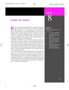
Physical Model A schematic of the PHP under investigation is shown in Fig. 1. A tube with diameter d and length 2nL is bent into n turns, with the two ends sealed. The evaporatorsections of the PHP are at the upper portion, and each of them has a length of L h . The condensersections with length L c are located at the lower portion of the PHP. The adiabatic sections, located between the evaporation and condenser sections,have a lengthof L a . The wall temperaturesat the evaporator and condenser sections are Te and Tc , respectively. The liquid slugs with uniform length2L p are locatedat the bottom of the PHP.7;10 The
Fig. 2
Heating and cooling sections of a PHP.
location of each liquid slug can be represented by the displacement x i , which is zero when the liquid slug is exactly in the middle of the turns. When the liquid slug shifts to the right, the displacement is positive. When the liquid slug shifts to the left, the displacement is negative. The operation of the PHP is accomplished by oscillation of the liquid slugs due to evaporationand condensation in the vapor plugs. Governing Equations
The momentum equation for the liquid slug in Fig. 2 can be expressed as 2A c L p ½`
d2 xi D . pv;i ¡ pv;i C 1 /A c ¡ 2½` g Ac x i ¡ 2¼ dL p ¿ p dt 2
(1)
where A c D ¼ d 2 =4 is the cross-sectional area of the tube. Equation (1) can be rearranged as pv;i ¡ pv;i C 1 g d2 x i 32ºe dx i C 2 C xi D Lp dt 2 d dt 2½` L p
(2)
where ºe is the effective kinetic viscosity of the liquid. The energy equation of the vapor plugs is obtained by application of the rst law of thermodynamics to each plug d.m v;i cv Tv;i / dm v;i ¼ d2 D c p Tv;i ¡ pv dt dt 4
³
dxi dxi ¡ 1 ¡ dt dt
´ (3)
Expansion of the left-hand side of Eq. (3) yields
³
m v;i cv
dTv;i dm v;i dm v;i ¼ d2 dx i dxi ¡ 1 C cv Tv;i D c p Tv;i ¡ pv ¡ dt dt dt 4 dt dt
´
which can be rearranged as m v;i cv
dTv;i dm v;i ¼ d2 D .c p ¡ cv /Tv;i ¡ pv dt dt 4
³
dx i dxi ¡ 1 ¡ dt dt
´
If the vapor can be consideredan ideal gas thatsatis es c p ¡ cv D R g , the energy equation in the vapor phase becomes
Fig. 1
PHP.
m v;i cv
dTv;i dm v;i ¼ d2 D R g Tv;i ¡ pv dt dt 4
³
dx i dxi ¡ 1 ¡ dt dt
´ (4)
342
ZHANG AND FAGHRI
The behavior of vapor plugs in the evaporators can be modeled by the use of the ideal gas law pv;1 [.L ¡ L p / C x 1 ].¼=4/d2 D m v;1 Rg Tv;1
(5a)
pv;i [2.L ¡ L p / C x i ¡ xi ¡ 1 ].¼=4/d2 D m v;i Rg Tv;i i D 2; 3; : : : ; n pv;n C 1 [.L ¡ L p / ¡ x n ].¼=4/d2 D m v;n C 1 R g Tv;n C 1
Nondimensional Governing Equations
To nondimensionalizethe governing equations, a reference state of the PHP needs to be speci ed. At this referencestate, the pressure and temperature of all of the vapor plugs are p0 and T0 , respectively. The displacement of all of the liquid plugs at the reference state are x i D x0 . According to Eq. (9), the constants Ci for different vapor plugs are the same and can be expressed as
¡
(5b) (5c)
m v;i R g Tv;i .dxi =dt ¡ dxi ¡ 1 =dt / dm v;i dTv;i D RTv;i ¡ (6) dt dt [2.L ¡ L p / C x i ¡ xi ¡ 1 ]
m v0;i D
¼ d2 p0 .L ¡ L p /; 2Rg T0
m v0;n C 1 D
(7)
where ° D c p =cv is the speci c heat ratio of the vapor. When Eq. (7) is integrated, a closed form of the mass of the vapor plug is obtained: m v;i D
1=.° ¡ 1/ C i Tv;i [2.L
¡ L p / C x i ¡ xi ¡ 1 ];
(8)
1=.° ¡ 1/ m v;1 D C 1 Tv;1 [.L ¡ L p / C x 1 ]
(8a)
1=.° ¡ 1/ m v;n C 1 D C n C 1 Tv;n C 1 [.L ¡ L p / ¡ x n ]
(8b)
m0 D
i D 1; 2; : : : ; n
(9)
The masses of the vapor plugs increase due to evaporation and decrease due to condensation
m v;i D m0
L h;R
L ¡ .L p ¡ x i / D 0
» L c;L D
L c ¡ .L p C x i ¡ 1 / 0
» L c;R D
L c ¡ .L p ¡ x i / 0
(14)
(15a)
± T ²1=° 2.L ¡ L / C x ¡ x p i i¡1 v;i
(15b)
2.L ¡ L p /
T0
T0
m v;nC1 D m0
2.L ¡ L p /
±T
v;n C 1
T0
²1=° L ¡ L ¡ x p n 2.L ¡ L p /
± T ²° =.° ¡ 1/
pv;i D p0
µi D Tv;i =T0 ;
v;i
(15c)
(16)
T0
Pi D Pv;i =P0 ;
X i D x i =x 0 ;
(10)
L p C xi ¡ 1 ¸ L c C L a L p C xi ¡ 1 < L c C L a
(11a)
L p ¡ xi ¸ L c C L a L p ¡ xi < L c C L a
(11b)
L p C xi ¡ 1 < L c L p C xi ¡ 1 ¸ L c
(11c)
L p ¡ xi < L c L p ¡ xi ¸ L c
(11d)
Mi D m v;i =m 0
" D L p =L
(17)
Eqs. (15) and (16) become
h
Mi D µi1=° 1 C
where L h;L and L h;R are lengths of evaporator sections that are in contact with the vapor plug, and L c;L and L c;R are lengths of condenser sections that are in contact with the vapor plug (Fig. 2).
»
(13c)
± T ²1=° L ¡ L C x v;1 p 1
m v;1 D m0
M1 D µ11=°
h c ¼ d.Tv;i ¡ Tc /.L c;L C L c;R / h fg
L ¡ .L p C xi ¡ 1 / 0
(13b)
Substitution of Eqs. (12) and (14) into Eqs. (8a), (8), (8b), and (9) yields
h e ¼ d.Te ¡ Tv;i /.L h;L C L h;R / dm v;i D h fg dt
L h;L D
¼d2 p0 [.L ¡ L p / ¡ x 0 ] 4R g T0
(13a)
By de nition of
4Ci Rg ° =.° ¡ 1/ T D ; ¼ d2 v;i
»
n D 2; 3; : : : ; n
m v0;1 C m v0;n C 1 ¼ d2 D p0 .L ¡ L p / D m v0;i 2 2R g T0
where C i is the integration constant. When Eqs. (8a), (8), and (8b) are substitued into Eqs. (5a–5c), the pressures of the vapor plug are pv;i
(12)
The average mass of the rst and last vapor plugs is
i D 2; 3; : : : ; n
Similarly, the masses of the rst and last vapor plug are
¡
¼ d2 p0 [.L ¡ L p / C x0 ] 4Rg T0
m v0;1 D
that is, 1 dm v;i 1 1 dTvi .d=dt /[.2L ¡ L p / C x i ¡ xi ¡ 1 ] D C m v;i dt ¡ T ° 1 v;i dt [.2L ¡ L p / C x i ¡ xi ¡ 1 ]
¢
The masses of the vapor plugs at the reference state are
When Eq. (5b) is substituted into Eq. (4) to eliminate vapor plug pressure, pv;i yields m v;i cv
¯
Ci D C D ¼ d 2 4R g p0 T0¡.° ¡ 1/=°
h
X1 1 C 2 2.1 ¡ "/
i (18a)
i
Xi ¡ Xi ¡ 1 ; 2.1 ¡ "/
Mn C 1 D µn1=° C1 Pi D µi° =.° ¡1/ ;
h1 2
¡
i D 2; 3; : : : ; n Xn 2.1 ¡ "/
(18b)
i (18c)
i D 1; 2; : : : ; n C 1
(19)
When the nondimensional variables are introduced to Eq. (2) and dimensionless time is de ned as ¿ D ºe t=d 2
(20)
Eq. (2) becomes d2 X i dX i C 32 C !20 X i D d¿ 2 d¿
.Pi ¡ Pi C 1 /;
i D 1; 2; : : : ; n (21)
343
ZHANG AND FAGHRI
where !0 and
Numerical Solution
are two dimensionless parameters de ned as !02 D
gd 4 ; L p ºe2
p0 d 4 2½` L p L h ºe2
D
(22)
Substituting Eqs. (17) and (20) into Eq. (10), one obtains ¡ ¢ dM i D He L ¤c;L C L ¤c;R .µe ¡ µi / d¿
¡
¡Hc L ¤c;L C L ¤c; R /.µi ¡ µc /
Pi ¡ Pi C 1 D Ai cos !i ¿ (23)
where
4h c RT02 d Hc D ; p0 h f g ºe µc D
Tc ; T0
Te T0
(24)
The dimensionless lengths of the vapor plug in the heating and cooling sections in Eq. (23) are » 1 ¡ ." C X i ¡ 1 / " C X i ¡ 1 ¸ 1 ¡ L ¤h L h;L L ¤h;L D D L 0 " C X i ¡ 1 < 1 ¡ L ¤h (25a) L ¤h;R D
L h;R D L
»
1 ¡ ." ¡ X i / 0
»
L ¤c;L D
L ¤c ¡ ." C X i ¡ 1 / L c;L D L 0
»
L ¤c;R D
" ¡ X i ¸ 1 ¡ L ¤h " ¡ X i < 1 ¡ L ¤h
L ¤c
¡ ." ¡ X i / L c;R D L 0
where L ¤h D L h =L ;
" C X i ¡ 1 < L ¤c " C X i ¡ 1 ¸ L ¤c " ¡ Xi < " ¡ Xi ¸
L ¤c L ¤c
L ¤c D L c =L
(25b)
(25c)
(25d)
(26)
The system is described by nine nondimensional parameters, including the number of turns n, and the parameters de ned in Eqs. (22), (24), and (26). If the reference temperature is chosen to be the average of Te and Tc , the dimensionless temperature of the heating and cooling sections is µe D 1 C 2;
µc D 1 ¡ 2
(27)
where 2 D .Te ¡ Tc /=.Te C Tc /
(28)
At this point, the number of dimensionlessparameters that describe the system are further reduced to eight. Initial Conditions
The reference state of the PHP is chosen to be the initial state of the system. The initial conditions of the system are Xi D X0;
¿ D 0;
i D 1; 2; : : : ; n
(29)
Pi D 1;
¿ D 0;
i D 1; 2; : : : ; n
(30)
µi D 1;
¿ D 0;
i D 1; 2; : : : ; n
(31)
M1 D
1 2
C X 0 =2.1 ¡ "/;
M i D 1; Mn C 1 D
¿ D 0; 1 2
¡ X 0 =2.1 ¡ "/;
¿ D0 i D 2; 3; : : : ; n ¿ D0
(32a) (32b) (32c)
(33)
the analytical solution of Eq. (21) can be obtained, and it will have the following form11 X i D Bi cos.!i ¿ ¡ ’i /
4h e RT02 d He D p0 h f g ºe µe D
The oscillatory ow in a PHP is describedby Eqs. (18), (19), (21), and (23), with initial conditions speci ed by Eqs. (29–32). Note that Eq. (21) is an ordinary differential equation of forced vibration. If the vapor pressure difference between the two vapor plugs at two ends of the liquid slug is
(34)
However, the amplitude and angular frequency are unknown a priori and the pressure difference between the two vapor plugs depends on heat transfer in two vapor plugs. The amplitude and angular frequency of pressure oscillation must be obtained numerically. The results of each time step are obtained when the dimensionless governing equations are solved with an implicit scheme. The numerical procedure for a particular time step is outlined as follows: 1) Guess the dimensionless temperatures of all vapor plugs µi . 2) Obtain the dimensionless vapor pressure Pi , from Eq. (19). 3) Calculate the dimensionless displacement of liquid slug X i from Eq. (21). 4) Calculate the mass of the vapor plugs Mi by the use of Eq. (23). 5) Calculate the nondimensional temperature of the vapor plugs µi from Eqs. (18a–18c). 6) Compare µi obtained in step 5 with the guessed values in step 1. If the differencesmeet a tolerance, go to the next step; otherwise, steps 2–5 are repeated until a converged solution is obtained. The use of an implicit scheme ensured the stability of the numerical solution. To obtain a time-step independent solution, the time step was systematicallyvaried to nd the appropriatetime step. The numerical results showed that the time-step independent solution can be obtained when the time step is 1¿ D 10¡5 because there are no notable changes in the results when the time step is reduced from 10¡5 to 10¡6 . All results presented in the following section were obtained by the use of the time step 1¿ D 10¡5 .
Results and Discussions Figure 3a shows the comparison of the liquid slug displacement obtained by the present model and the model of Zhang et al.11 who studied oscillatory ow in a U-shaped miniature channel. The present result is obtained by the set of the number of turns, n D 1. Note that the agreement between the results obtained by the present model and Zhang et al.11 is excellent. Figure 3b shows the comparison of the liquid slug displacements obtained by the present model and the model of Sha i et al.10 The results of the Sha i et al. model10 were obtainedwith the followingparameters: L h D 0:1 m, L a D 0 m, L c D 0:1 m, L p D 0:2 m, d D 3:34 mm, Te D 123:4± C, Tc D 20± C, and h e D h c D 200 W/m2 K. The present results were obtained with the corresponding nondimensional parameters: !02 D 1:2 £ 104 , D 1:2 £ 105 , 2 D 0:15, He D Hc D 3000, L ¤h D 0:5, L ¤c D 0:5, and n D 2. Note that the results obtained with the present model agreed very well with the results obtained by the Sha i et al. model,10 which employed dimensional parameters and was applicable only to PHPs with two turns. The phase of the oscillation of two vapor plugs are the same for the rst several periods. Steady oscillation is established after ¿ D 0:09, at which time the amplitudes of oscillation for the two liquid slugs are the same. The phase difference for the oscillation of the two liquid slugs is equal to ¼ , which means that the oscillation of the liquid slug in the PHP with two turns is symmetric after steady oscillation is established.The amplitude and circular frequency for oscillation in a PHP with two turns are the same as those for a U-shaped channel. At the parameters just speci ed, the amplitude and circular frequency of oscillation for both n D 1 and n D 2 are B D 0:31489 and ! D 597:78, respectively. As indicated in the numerical simulations by Sha i et al.10 and Zhang
344
ZHANG AND FAGHRI
frequency are desirable for better heat transfer performance of the PHP. Figure 4a shows the dimensionless temperature of three vapor plugs. The maximum temperature of the vapor plug can exceed the heating wall temperature of the PHP due to compression of the vapor plug. The variations of the dimensionless temperatures of the rst and third vapor plugs become identical after steady oscillation is established at ¿ D 0:09. Figure 4b shows the variation of
a)
a)
b) Fig. 3 Comparison of the present results with a) Zhang et al.11 and b) Sha i et al.10
b) Fig. 5 Dimensionlessa) displacement of liquid slugs and dimensionless b) temperature of the vapor plugs (n = 3).
a)
a)
b) Fig. 4 Dimensionless a) temperature and b) mass of the vapor plugs (n = 2).
and Faghri,12 heat transfer in a PHP is mainly due to the exchange of sensible heat, that is, liquid slugs absorb heat in the heating sections and release heat in the cooling section of the PHP. The large amplitude of the oscillatory ow allows the liquid slug to achieve better contact with the heating and cooling sections of the PHP. On the other hand, a large circular frequency of oscillatory ow allows quicker motion of liquid slug between the heating and cooling sections of the PHP. Therefore, both large amplitudeand highercircular
b) Fig. 6 Dimensionlessa) displacement of liquid slugs and dimensionless b) temperature of the vapor plugs (n = 4).
345
ZHANG AND FAGHRI
dimensionlessmass of the vapor plugs. The masses of rst and third vapor plugs were different at the beginning, but they are identical after steady oscillation is established. The mass of the second vapor plug is twice that of rst or third vapor plugs after steady oscillation is established. The history of vapor plug temperature and mass further indicated that the oscillations in the PHP with two turns are symmetric. The differences between the oscillations in PHP with one or two turns can be observed before steady oscillation is established. After steady oscillation is established, the oscillation in the U-shaped channel is the same as that in the PHP with two turns. Figure 5 shows oscillatory ow in a PHP with three turns. The time required to establish steady oscillation for the PHP with three turns is longer than that for the PHP with two turns. Once steady oscillation is established, the dimensionless displacements of the rst and third liquid slugs become identical, which means that the oscillation is symmetric for the PHP with three turns. Figure 5b shows the dimensionless temperatures of the vapor plugs for the PHP with three turns. The dimensionless temperatures of an odd number of vapor plugs are identical once steady oscillation is established.The dimensionless temperature of an even number of vapor plugs are also identical once steady oscillation is established, but their phase
difference with odd numbered vapor plugs is ¼ . The amplitude and circular frequency of oscillation are same as those of n D 1 and 2. Figure 6 shows oscillatory ow in a PHP with four turns. The time required to establish steady oscillation for the PHP with four turns is about ¿ D 0:13, which is longer than that for PHP with three turns. The dimensionlessdisplacementsof the odd-numberedliquid slugs become identical once steady oscillation is established. The dimensionless displacementsof the even-numbered liquid slugs are also identical after ¿ D 0:13. Figure 5b shows the dimensionless temperature of the vapor plugs for the PHP with four turns. Similar to the case with three turns, the phase difference between odd- and even-numbered vapor plugs is also ¼ . The increase in the number of turns from three to four did not result in any changes in the amplitude and circular frequency of oscillation. Numerical simulationsare then performedfor PHPs with different numbers of turns. The results show that the amplitude and frequency of oscillation of PHPs are not affected by the number of turns until n D 6. When the number of turns is increasedto 6, the amplitude and frequency of oscillation for differentliquid slugs begin to differ. The
a) Odd number liquid slugs a) Odd number liquid slugs
b) Even number liquid slugs b) Even number liquid slugs Fig. 7
Fig. 8
Fig. 9
Displacement of liquid slugs (L¤h = L¤c = 0.45).
Displacement of liquid slugs (n = 10).
Distribution of the displacement of liquid slugs (n = 10).
Fig. 10 Distribution of the displacement of liquid slugs (L¤h = L¤c = 0.45).
346
ZHANG AND FAGHRI
n=6
n=7
n=8
n=9
n = 10
B !
0.3150 597.78
0.3157 597.25
0.3165 597.25
0.3098 599.39
3.3191 596.18
B !
0.3155 597.78
0.3150 597.78
0.3151 597.25
0.3117 599.39
0.3155 596.18
Figure 7 shows the dimensionless displacements of liquid slugs for a PHP with 10 turns after steady oscillation is established. The phases of oscillationfor all odd-numberedliquid slugs are very close to each other, and the phases of oscillation for all even-numbered liquid slugs are also very close to each other. The phase difference between any two adjacent liquid slugs is approximately¼ . Figure 8 shows the overall displacements of liquid slugs at four different times. The oscillations of any two adjacent liquid slugs are nearly always in opposing directions.The delay of oscillation for the i th slug relative to the .i ¡ 2/th slug is also clearly seen from Fig. 8. Figure 9 shows the displacements of liquid slugs for L ¤h D L ¤c D 0:45. The overall distribution of the displacements of liquid slugs at four different times is shown in Fig. 10. The delay of oscillation for the i th slug relative to the .i ¡ 2/th slug is more signi cant when the lengths of the heating and cooling sections are reduced. The amplitude and circular frequency of oscillation are listed in Table 2. Both the amplitude and circular frequency of oscillation are decreased
B !
0.3151 598.32
0.3141 597.78
0.3144 597.78
0.3142 599.39
0.3155 596.71
Table 2 Effects of heating/cooling section length and charge ratio on amplitude and circular frequency
B !
0.3144 597.78
0.3135 597.78
0.3129 597.78
0.3156 598.85
0.3119 597.25
i
B !
0.3136 597.78
0.3128 598.32
0.3117 598.32
0.3190 598.32
0.3106 597.25
1
B !
0.3144 597.78
0.3116 598.32
0.3115 598.32
0.3217 597.25
0.3098 598.32
2
B !
—— ——
0.3132 598.85
0.3118 598.85
0.3232 596.18
0.3094 598.32
3
B !
—— ——
—— ——
0.3119 598.32
0.3241 595.65
0.3100 598.85
4
B !
—— ——
—— ——
—— ——
0.3230 595.12
0.3108 599.39
5
B !
—— ——
—— ——
—— ——
—— ——
0.3115 599.39
6
amplitude and circular frequencyof oscillation for differentnumber of turns are shown in Table 1. The amplitude and circular frequency for different liquid slugs in the same PHP are slightly different when the number of turns is greater than ve. However, note that the amplitudes and circular frequencies for different turns are only very slightly different. When n D 10, the maximum differences of the amplitudes and circular frequencies for different turns are only 3 and 0.5%, respectively. Table 1 Amplitude and circular frquency of oscillatory ow in PHPs i 1 2 3 4 5 6 7 8 9 10
7 8 9 10
L ¤h = 0.5 " = 0.4
L ¤h = 0.45 " = 0.4
L ¤h = 0.5 " = 0.45
B !
0.3191 596.18
0.3187 581.65
0.2816 638.32
B !
0.3155 596.18
0.3141 582.16
0.2807 638.93
B !
0.3135 596.71
0.3088 582.67
0.2803 638.93
B !
0.3119 597.25
0.3052 583.17
0.2796 639.54
B !
0.3106 597.25
0.3044 583.68
0.2792 638.93
B !
0.3098 598.32
0.3044 584.19
0.2789 639.54
B !
0.3094 598.32
0.3044 584.71
0.2790 639.54
B !
0.3100 598.85
0.3055 584.71
0.2797 639.54
B !
0.3108 599.39
0.3064 585.22
0.2797 639.54
B !
0.3115 599.39
0.3071 585.22
0.2787 639.54
a) Odd number liquid slugs
b) Even number liquid slugs Fig. 11
Displacement of liquid slugs (" = 0.45).
Fig. 12
Distribution of the displacement of liquid slugs (" = 0.45).
ZHANG AND FAGHRI
because the available heating and cooling section areas are decreased. Figure 11 shows the displacements of liquid slugs for the charge ratio of 0:45. The overall distribution of the displacements of liquid slugs at four different times is shown in Fig. 12. The oscillations of the i th slug relative to the .i ¡ 2/th slug are closer to one another. The amplitude and circular frequency of oscillation for an increased charge ratio are also listed in Table 2. The amplitude of oscillation is decreased because the mass of the liquid slug is larger for a large charge ratio. On the other hand, the circular frequency of oscillation is increased.
Conclusions Oscillatory ow in a PHP with an arbitrary number of turns is investigated in the present study. The governing equations that describe the oscillatory ow were nondimensionalized, and the parameters that describe the system were reduced to eight nondimensional parameters. The results show that the increase in the number of turns has no effect on the amplitude and circular frequency of oscillation when the number of turns is less than or equal to ve. When the number of turns is increased to more than ve, the amplitude and circular frequency of oscillation for different liquid slugs are shown. Both the amplitude and circular frequency of oscillation will decrease when the lengths of the heating and cooling sections are decreased. When the charge ratio is increased, the amplitudes of oscillation decrease, and the circular frequency of oscillation increases.
Acknowledgments This work was partially supported by NASA Grant NAG3-1870 and National Science Foundation Grant CTS 9706706.
References 1 Akachi,
H., “Looped Capillary Heat Pipe,” Japanese Patent No. Hei697147, 1994.
347
2 Faghri, A., Heat Pipe Science and Technology, Taylor and Francis, Washington, DC, 1995. 3 Akachi, H., Polasek, F., and Stulc, P., “Pulsating Heat Pipes,” Proceedings of the 5th International Heat Pipe Symposium, Royal Melbourne Inst. of Technology, Melbourne, Australia, 1996, pp. 208–217. 4 Gi, K., Maezawa, K. Y., and Yamazaki, N., “CPU Cooling of Notebook PC by Oscillating Heat Pipe,” Proceedings of the 11th International Heat Pipe Conference, Japan Association for Heat Pipes, Tokyo, Japan, 1999, pp. 166–169. 5 Miyazaki, Y., and Akachi, H., “Heat Transfer Characteristics of Looped Capillary Heat Pipe,” Proceedings of the 5th International Heat Pipe Symposium, Royal Melbourne Inst. of Technology, Melbourne, Australia, 1996, pp. 378–383. 6 Miyazaki, Y., and Akachi, H., “Self Excited Oscillation of Slug Flow in a Micro Channel,” Proceedings of the 3rd International Conference on Multiphase Flow, Lyon, France, 1998. 7 Miyazaki, Y., and Arikawa, M., “Oscillatory Flow in the Oscillating Heat Pipe,” Proceedings of the 11th International Heat Pipe Conference, Japan Association for Heat Pipes, Tokyo, Japan, 1999, pp. 131– 136. 8 Lee, W. H., Jung, H. S., Kim, J. H., and Kim, J. S., “Flow Visualization of Oscillating Capillary Tube Heat Pipe,” Proceedings of the 11th International Heat Pipe Conference, Japan Association for Heat Pipes, Tokyo, Japan, 1999, pp. 131–136. 9 Hosoda, M., Nishio, S., and Shirakashi, R., “Meandering Closed-Loop Heat-Transport Tube (Propagation Phenomena of Vapor Plug),” Proceedings of the 5th ASME/JSME Joint Thermal Engineering Conference, American Society of Mechanical Engineers, New York, 1999 [CD-ROM]. 10 Sha i, M. B., Faghri, A., and Zhang, Y., “Thermal Modeling of Unloopedand LoopedPulsating Heat Pipes,” Journal of Heat Transfer, Vol. 123, No. 6, 2001, pp. 1159–1172. 11 Zhang, Y., Faghri, A. and Sha i, M. B., “Analysis of Liquid–Vapor Pulsating Flow in a U-Shaped Miniature Tube,” International Journal of Heat and Mass Transfer, Vol. 45, No. 12, 2002, pp. 2501–2508. 12 Zhang, Y., and Faghri, A., “Heat Transfer in a Pulsating Heat Pipe with Open End,” International Journal of Heat and Mass Transfer, Vol. 45, No. 4, 2002, pp. 755–764.