Hindawi Shock and Vibration Volume 2017, Article ID 8176593, 14 pages https://doi.org/10.1155/2017/8176593
Research Article Output-Only Modal Parameter Recursive Estimation of Time-Varying Structures via a Kernel Ridge Regression FS-TARMA Approach Zhi-Sai Ma, Li Liu, Si-Da Zhou, and Lei Yu School of Aerospace Engineering, Beijing Institute of Technology, Zhongguancun South Street 5, Beijing 100081, China Correspondence should be addressed to Si-Da Zhou;
[email protected] Received 21 July 2016; Revised 2 November 2016; Accepted 29 November 2016; Published 11 January 2017 Academic Editor: Lu Chen Copyright © 2017 Zhi-Sai Ma et al. This is an open access article distributed under the Creative Commons Attribution License, which permits unrestricted use, distribution, and reproduction in any medium, provided the original work is properly cited. Modal parameter estimation plays an important role in vibration-based damage detection and is worth more attention and investigation, as changes in modal parameters are usually being used as damage indicators. This paper focuses on the problem of output-only modal parameter recursive estimation of time-varying structures based upon parameterized representations of the time-dependent autoregressive moving average (TARMA). A kernel ridge regression functional series TARMA (FS-TARMA) recursive identification scheme is proposed and subsequently employed for the modal parameter estimation of a numerical threedegree-of-freedom time-varying structural system and a laboratory time-varying structure consisting of a simply supported beam and a moving mass sliding on it. The proposed method is comparatively assessed against an existing recursive pseudolinear regression FS-TARMA approach via Monte Carlo experiments and shown to be capable of accurately tracking the time-varying dynamics in a recursive manner.
1. Introduction The need for damage identification or fault diagnosis of a structure is pervasive throughout the aerospace, shipbuilding, manufacturing, infrastructure, and transportation engineering communities. In recent years, many efforts have been undertaken to detect, locate, and characterize damage in structural systems by examining changes in measured vibration responses, which may be collectively referred to as vibration-based damage identification or fault diagnosis [1–5]. Compared with visual or localized methods, vibrationbased methods offer a number of potential advantages, as they require no visual inspection, are capable of working at a “system level” especially when the portion of the structure being inspected is not accessible, and can monitor a structure under its operating conditions [1–5]. The basic idea behind this technology is that changes in the physical properties of a structure will cause detectable changes in its modal parameters (natural frequencies, damping ratios, and mode shapes), as the modal parameters are functions of the physical properties of the structure (mass, damping, and stiffness) [1].
Because changes in modal parameters are usually being used as damage indicators, modal parameter estimation plays an important role in vibration-based damage detection of structures and is worth more attention and investigation. Most structures in the real world are time-varying under a specific time scale and their intrinsic time-varying behavior is increasingly inevitable in industry. Typical examples include vibration absorbers with variable stiffness, bridges with crossing vehicles, launch vehicles with varying fuel mass, airplanes with varying additional aerodynamic effects in flight, deployable space structures, and rotating machinery. In contrast to time-invariant systems producing stationary responses with time-invariant statistical characteristics [6], timevarying systems exhibit time-varying/nonstationary characteristics, requiring time-dependent dynamic models and corresponding identification methods. Therefore, time-varying system identification becomes increasingly more important [7–12]. This paper focuses on the problem of output-only modal parameter recursive estimation of time-varying structures due to the following two reasons. Firstly, in many cases
2 controlled testing may not be feasible or the excitation may be unobservable under realistic operating conditions. Hence, there exists a need to estimate modal parameters of timevarying structures by exclusively using the available measured vibration responses (referred to as output-only modal parameter estimation). Secondly, in many practical cases in which the data observations are arriving in a continuous stream, the structure has to be identified before all of the response measurements are known. Hence, there also exists a need to estimate modal parameters of time-varying structures in a recursive instead of batch manner. Many output-only identification methods have been developed based on parameterized representations of the time-dependent autoregressive moving average (TARMA) [10–14]. TARMA model-based identification methods are divided into three main classes, depending on the type of “structure” imposed upon the evolution of the time-varying model parameters [11, 12]: unstructured parameter evolution (UPE) methods, stochastic parameter evolution (SPE) methods, and deterministic parameter evolution (DPE) methods. Most of the output-only recursive identification methods are currently of the UPE type [9–13], which may be not suitable for fast varying structures as they impose no “structure” upon their model parameters [10–12]. These methods include the recursive maximum likelihood TARMA method [9–11] and the recursive pseudolinear regression TARMA (RPLRTARMA) method [9, 10, 13]. In contrast with the UPE/SPE methods, the DPE methods are based on explicit models of the parameter variation. These models are achieved by approximating the parameter trajectory by a linear combination of known basis functions, belonging to specific functional subspaces. Such representations are generally referred to as functional series TARMA (FS-TARMA) representations/models [11–14]. Although different recursive DPE methods have been developed in recent years, their tracking capability of time-varying dynamics may be limited and more efforts are still needed [10–20]. From this point of view the FSTARMA model-based recursive methods are promising and are therefore investigated in this work. The remainder of the paper is organized as follows: Section 2 introduces the FS-TARMA model-based modal parameter estimation. The existing recursive pseudolinear regression FS-TARMA (RPLR-FS-TARMA) approach is reviewed in Section 3. Section 4 proposes a kernel ridge regression FSTARMA (KRR-FS-TARMA) approach consisting of parameter matrix estimation and the corresponding model structure selection. The proposed method is, along with the existing RPLR-FS-TARMA method, numerically and experimentally validated in Sections 5 and 6, respectively. Section 7 summarizes the study.
2. FS-TARMA Model-Based Modal Parameter Estimation 2.1. TARMA Model. The TARMA representation resembles its stationary counterparts, with the significant difference being that it allows its parameters to depend upon time [10–12]. A TARMA (𝑛𝑎 , 𝑛𝑐 ) model, with 𝑛𝑎 , 𝑛𝑐 designating,
Shock and Vibration respectively, its autoregressive (AR) and moving average (MA) orders, is of the form [13] 𝑛𝑎
𝑛𝑐
𝑖=1
𝑖=1
x [𝑡] + ∑A𝑖 [𝑡] x [𝑡 − 𝑖] = e [𝑡] + ∑C𝑖 [𝑡] e [𝑡 − 𝑖] ,
(1)
e [𝑡] ∼ N (0, Σ [𝑡]) with 𝑡 designating normalized (by the sampling period) discrete time, x[𝑡] ∈ R𝑘×1 the discrete-time nonstationary vibration signal to be modeled, and e[𝑡] ∈ R𝑘×1 an unobservable uncorrelated innovation (residual) sequence with zero mean and time-varying nonsingular covariance matrix Σ[𝑡] ∈ R𝑘×𝑘 . A𝑖 [𝑡] and C𝑖 [𝑡] are, respectively, the model’s AR and MA parameter matrices. N(⋅, ⋅) stands for normally independently distributed random variables with the indicated mean and covariance. Once the time-dependent AR parameter matrix A𝑖 [𝑡] has been obtained, the system’s “frozen-time” poles can be derived by solving the following general eigenvalue problem [14] (D [𝑡] − 𝑝𝑟 [𝑡] I𝑘𝑛𝑎 ) V𝑟 [𝑡] = 0,
𝑟 = 1, 2, . . . , 𝑘𝑛𝑎 ,
(2)
where I𝑘𝑛𝑎 designates the identity matrix of order 𝑘𝑛𝑎 and 𝑝𝑟 [𝑡] and V𝑟 [𝑡] = [𝑝𝑟 [𝑡]−𝑛𝑎 L𝑇𝑟 , . . . , 𝑝𝑟 [𝑡]−1 L𝑇𝑟 ]𝑇 are the 𝑟th pole and eigenvector of D[𝑡] at instant of time 𝑡 with the 𝑟th mode shape L𝑟 , respectively. The matrix D[𝑡] is constructed from the AR parameter matrices as [ [ [ D [𝑡] = [ [ [ [
0
I𝑘
⋅⋅⋅
0
.. .
.. .
d
.. .
0
0
⋅⋅⋅
I𝑘
] ] ] ]. ] ] ]
(3)
[−A𝑛𝑎 [𝑡] −A𝑛𝑎 −1 [𝑡] ⋅ ⋅ ⋅ −A1 [𝑡]]
The system’s “frozen-time” modes with natural frequencies and damping ratios are computed by [6] ln 𝑝𝑟 [𝑡] , 𝑓𝑟 [𝑡] = 2𝜋Δ𝑡 𝜁𝑟 [𝑡] =
−Re (ln 𝑝𝑟 [𝑡]) , ln 𝑝𝑟 [𝑡]
(4) 𝑟 = 1, 2, . . . , 𝑘𝑛𝑎
in which | ⋅ | denotes the absolute value and Δ𝑡 the sampling period. 2.2. FS-TARMA Model. Any given function can be approximated by a set of selected basis functions with arbitrary accuracy, as long as a sufficient number of basis functions are used [21]. Hence, a time-varying parameter V[𝑡] can be expressed as 𝑝V
V [𝑡] = ∑ V𝑗 ⋅ 𝐺𝑏V (𝑗) [𝑡] , 𝑗=1
(5)
Shock and Vibration
3
where 𝐺𝑏V (𝑗) [𝑡] denotes a set of basis functions selected from a suitable functional subspace (such as trigonometric, Legendre, Chebyshev, wavelets, B-splines, and moving Kriging shape functions), V𝑗 coefficient of projection, 𝑝V the subspace dimensionality, and the index 𝑏V (𝑖) (𝑖 = 1, . . . , 𝑝V ) the specific basis functions of the selected functional subspace that are included in the basis. By using (5), the time-dependent AR and MA parameter matrices A𝑖 [𝑡] and C𝑖 [𝑡] can be, respectively, expressed as [11– 14] 𝑝𝑎
𝑝𝑎
𝑖,𝑗
𝑝𝑐
𝑖,𝑗
𝑖,𝑗
𝑖=1
𝑖=1
∈R
(6)
𝑖,𝑗
x [𝑡] = −∑A𝑖 [𝑡] x [𝑡 − 𝑖] + ∑C𝑖 [𝑡] e [𝑡 − 𝑖] + e [𝑡] ⇒
(7)
𝑇
x [𝑡] = 𝜃 𝜙 [𝑡] + e [𝑡] with 1,𝑝
[ [ 𝜃=[ [
𝑛 ,𝑝𝑐
𝑛 ,1
1,1 ⋅ ⋅ ⋅ 𝑎1,1 𝑎 ⋅ ⋅ ⋅ 𝑐1,𝑘𝑐 ⋅ ⋅ ⋅ 𝑐1,𝑘𝑐 𝑎1,1
.. .
.. .
d 1,𝑝
∈R
,
(11)
Substituting (6) into (1), the TARMA model can be rewritten into the following FS-TARMA model: 𝑛𝑐
(10) 𝑝𝑎 ×1
g𝑏𝑐 [𝑡] = [𝐺𝑏𝑐 (1) [𝑡] , 𝐺𝑏𝑐 (2) [𝑡] , . . . , 𝐺𝑏𝑐 (𝑝𝑐 ) [𝑡]]
[ ∑ 𝑐1,1 ⋅ 𝐺𝑏𝑐 (𝑗) [𝑡] ⋅ ⋅ ⋅ ∑ 𝑐1,𝑘 ⋅ 𝐺𝑏𝑐 (𝑗) [𝑡]] ] [𝑗=1 𝑗=1 ] [ ] [ . . .. .. ]. C𝑖 [𝑡] ≈ [ d ] [ ] [𝑝 𝑝𝑐 ] [ 𝑐 𝑖,𝑗 ] [ 𝑖,𝑗 ∑𝑐𝑘,1 ⋅ 𝐺𝑏𝑐 (𝑗) [𝑡] ⋅ ⋅ ⋅ ∑𝑐𝑘,𝑘 ⋅ 𝐺𝑏𝑐 (𝑗) [𝑡] 𝑗=1 ] [𝑗=1
𝑛𝑎
𝑇
g𝑏𝑎 [𝑡] = [𝐺𝑏𝑎 (1) [𝑡] , 𝐺𝑏𝑎 (2) [𝑡] , . . . , 𝐺𝑏𝑎 (𝑝𝑎 ) [𝑡]]
𝑇
[ ∑ 𝑎1,1 ⋅ 𝐺𝑏𝑎 (𝑗) [𝑡] ⋅ ⋅ ⋅ ∑ 𝑎1,𝑘 ⋅ 𝐺𝑏𝑎 (𝑗) [𝑡]] [𝑗=1 ] 𝑗=1 [ ] [ ] . . . . [ ], A𝑖 [𝑡] ≈ [ . d . ] [𝑝 ] 𝑝𝑎 [ 𝑎 ] 𝑖,𝑗 𝑖,𝑗 [ ] ∑𝑎𝑘,1 ⋅ 𝐺𝑏𝑎 (𝑗) [𝑡] ⋅ ⋅ ⋅ ∑𝑎𝑘,𝑘 ⋅ 𝐺𝑏𝑎 (𝑗) [𝑡] 𝑗=1 [𝑗=1 ] 𝑝𝑐
the corresponding regression vector, where ⊗ is the Kronecker product [22] and g𝑏𝑎 [𝑡] and g𝑏𝑐 [𝑡] are, respectively, given by
𝑛 ,1
𝑛 ,𝑝
𝑇
] ] ] ]
1,1 𝑎 𝑐 𝑐 𝑐 [𝑎𝑘,1 ⋅ ⋅ ⋅ 𝑎𝑘,1 ⋅ ⋅ ⋅ 𝑐𝑘,𝑘 ⋅ ⋅ ⋅ 𝑐𝑘,𝑘 ]
(8)
∈ R𝑘(𝑛𝑎 𝑝𝑎 +𝑛𝑐 𝑝𝑐 )×𝑘
𝑝𝑐 ×1
.
Unlike the TARMA model of (1), the parameter matrix of the FS-TARMA model of (7) is time-invariant; that is, 𝜃 is a time-invariant matrix. In other words, a time-varying TARMA model can be transformed into a time-invariant FS-TARMA model by expanding the time-dependent model parameters onto the selected functional subspaces. The parameter matrix 𝜃 may be thus estimated by means of timeinvariant system identification techniques, while the timedependent AR and MA parameter matrices A𝑖 [𝑡] and C𝑖 [𝑡] may be subsequently estimated by using (6), after substituting ̂ 𝜃 by the obtained estimate 𝜃.
3. Recursive Pseudolinear Regression FS-TARMA Approach So far, we have presented that modal parameters can be extracted from the FS-TARMA model parameter matrix ̂ The problem of FS-TARMA model parameter estimate 𝜃. matrix estimation based on the existing recursive pseudolinear regression scheme is reviewed in this section. 3.1. RPLR-FS-TARMA Method. The FS-TARMA model is time-invariant, as shown in (7), and the well-known recursive pseudolinear regression scheme [9, 10] can be utilized to accomplish the estimation of 𝜃. Given the regularization parameter 𝛾 ≥ 0, the regularized least squares cost function is defined as
being the time-invariant parameter matrix, and −x [𝑡 − 1] ⊗ g𝑏𝑎 [𝑡]
[ ] .. [ ] [ ] . [ ] [ ] [−x [𝑡 − 𝑛𝑎 ] ⊗ g𝑏𝑎 [𝑡]] 𝑘(𝑛𝑎 𝑝𝑎 +𝑛𝑐 𝑝𝑐 )×1 ] 𝜙 [𝑡] = [ [ e [𝑡 − 1] ⊗ g [𝑡] ] ∈ R [ ] 𝑏𝑐 [ ] [ ] . [ ] .. [ ]
min 𝜃
(9)
1 𝑡 2 1 [ ∑ x [𝜏] − 𝜃𝑇 𝜙 [𝜏] + 𝛾 ‖𝜃‖2 ] , 2 𝜏=1 2
where ‖ ⋅ ‖ denotes the Euclidean norm. The RPLR-FSTARMA method can be obtained by minimizing the cost function of (12) and is summarized in the following [11]:
[ e [𝑡 − 𝑛𝑐 ] ⊗ g𝑏𝑐 [𝑡] ] Estimator update:
(12)
𝜃̂ [𝑡]𝑇 = 𝜃̂ [𝑡 − 1]𝑇 + ̂e [𝑡 | 𝑡 − 1] K [𝑡]𝑇 ,
4
Shock and Vibration Prediction error: ̂e [𝑡 | 𝑡 − 1] = x [𝑡] − x̂ [𝑡 | 𝑡 − 1] = x [𝑡] − 𝜃̂ [𝑡 − 1]𝑇 𝜙 [𝑡] , Gain: Covariance update:
−1
K [𝑡] = P [𝑡 − 1] 𝜙 [𝑡] (1 + 𝜙 [𝑡]𝑇 P [𝑡 − 1] 𝜙 [𝑡]) , P [𝑡] = P [𝑡 − 1] − K [𝑡] 𝜙 [𝑡]𝑇 P [𝑡 − 1] . (13)
By recursively applying (13) to the data record x[𝑡] (𝑡 = 1, . . . , 𝐿), the final parameter matrix estimate can be obtained ̂ 𝑇 , where 𝐿 is the length of the data record. For the as 𝜃[𝐿] ̂ 𝑇 = 0, initialization of the method it is customary to set 𝜃[0] −1 P[0] = 𝛾 I𝑘(𝑛𝑎 𝑝𝑎 +𝑛𝑐 𝑝𝑐 ) . It should be further stressed that the recursive scheme may yield biased parameter estimates even if parameters can be described exactly as weighted sums of basis functions, as the regression matrix 𝜙[𝑡] contains entries that are constructed from data using past models. Generally, the capability of the RPLR-FS-TARMA method is limited due to the following four reasons. Firstly, ̂ 𝑇 is recursively updated at each time step, the estimate 𝜃[𝑡] ̂ 𝑇 involves processing the entire but the final estimate 𝜃[𝐿] data record. Hence, the RPLR-FS-TARMA method is a recursive, but not a real-time, time-varying system identification method. Secondly, the RPLR-FS-TARMA method, as a member of running-basis estimators [10], will encounter numerical problems in case that the basis sequences are not bounded. Hence, this method may be limited to the cases in which 𝐿 is known and the basis functions can be scaled in advance. Thirdly, we have to consider the problem of data saturation [23], which means we may reach a point in our analysis of data that sampling more data will not lead ̂ 𝑇 . Hence, this method to more accurate estimation of 𝜃[𝐿] may be limited to the cases in which 𝐿 is not so large or
Estimator update:
data saturation can be avoided. Finally, with the increase in 𝐿, the difficulty of expanding the time-dependent model parameters onto specific functional subspaces increases as well. For example, the selection of a suitable functional subspace could be very difficult, and the subspace dimensionalities 𝑝𝑎 and/or 𝑝𝑐 could be quite large. Hence, the superior achievable accuracy, lower computational complexity, and enhanced tracking capability of the RPLR-FS-TARMA method will not be guaranteed any more. 3.2. Exponentially Weighted RPLR-FS-TARMA Method. In order to avoid some of those limitations of the RPLRFS-TARMA method, the exponentially weighted RPLR-FSTARMA method is presented by including an exponentially weighted mechanism in the RPLR-FS-TARMA method [9, 11, 13]. Given the forgetting factor 0 < 𝜆 ≤ 1 (a positive scalar, usually close to one) and the regularization parameter 𝛾 ≥ 0, the exponentially weighted regularized least squares cost function is defined as min 𝜃[𝑡]
1 𝑡 2 1 [ ∑ 𝜆𝑡−𝜏 x [𝜏] − 𝜃 [𝑡]𝑇 𝜙 [𝜏] + 𝜆𝑡 𝛾 ‖𝜃 [𝑡]‖2 ] . (14) 2 𝜏=1 2
The exponentially weighted RPLR-FS-TARMA method can be obtained by minimizing the cost function of (14) and is summarized in the following [9, 11, 13]:
𝜃̂ [𝑡]𝑇 = 𝜃̂ [𝑡 − 1]𝑇 + ̂e [𝑡 | 𝑡 − 1] K [𝑡]𝑇 ,
Prediction error: ̂e [𝑡 | 𝑡 − 1] = x [𝑡] − x̂ [𝑡 | 𝑡 − 1] = x [𝑡] − 𝜃̂ [𝑡 − 1]𝑇 𝜙 [𝑡] , Gain: Covariance update:
𝑇
−1
(15)
K [𝑡] = P [𝑡 − 1] 𝜙 [𝑡] (𝜆 + 𝜙 [𝑡] P [𝑡 − 1] 𝜙 [𝑡]) , P [𝑡] = 𝜆−1 (P [𝑡 − 1] − K [𝑡] 𝜙 [𝑡]𝑇 P [𝑡 − 1]) .
By recursively applying (15) to the data record x[𝑡] (𝑡 = 1, . . . , 𝐿), the parameter matrix estimate at each time ̂ 𝑇 . Similarly, for the initialization step can be obtained as 𝜃[𝑡] ̂ 𝑇 = 0, P[0] = of the method it is customary to set 𝜃[0] 𝛾−1 I𝑘(𝑛𝑎 𝑝𝑎 +𝑛𝑐 𝑝𝑐 ) . Obviously, the exponentially weighted RPLRFS-TARMA method reduces to the RPLR-FS-TARMA method of (13), when 𝜆 = 1. Besides, the exponentially weighted RPLR-FS-TARMA method reduces to the exponentially weighted RPLR-TARMA method [9, 13], when 𝑝𝑎 = 𝑝𝑐 = 1, 𝐺𝑏𝑎 (1) [𝑡] = 𝐺𝑏𝑐 (1) [𝑡] = 1. Some limitations of the RPLR-FS-TARMA method are relaxed by using the exponentially weighted mechanism.
̂ 𝑇 is recursively estimated at each Firstly, the estimate 𝜃[𝑡] time step, allowing the exponentially weighted RPLR-FSTARMA method to operate in real-time. Secondly, even if 𝐿 is unknown, the exponentially weighted RPLR-FS-TARMA method can be still implemented by selecting a suitable functional subspace with bounded basis sequences (which is the case when a trigonometric basis is used). Thirdly, the problem of data saturation is successfully overcome by putting more emphasis on recent data and deemphasizing data from remote past. Unfortunately, the exponentially weighted RPLR-FSTARMA method may be an impractical method due to its
Shock and Vibration
5
fatal drawback. The FS-TARMA model structure calls for a ̂ 𝑇 constant parameter matrix. Therefore, if the estimate 𝜃[𝑡] is used as the projection coefficients of the time-dependent AR and MA parameter matrices of (6) at each time step, the structured parameter evolution will be partially violated. In other words, the exponentially weighted RPLR-FS-TARMA method loses those advantages of the DPE methods and sometimes even underperforms its UPE counterpart, that is, the exponentially weighted RPLR-TARMA method [9, 13].
4. Kernel Ridge Regression FS-TARMA Approach In the previous section we have reviewed the RPLR-FSTARMA approach which suffers from many limitations. This section proposes a kernel ridge regression FS-TARMA approach which can outperform the RPLR-FS-TARMA approach in terms of achievable accuracy and tracking capability. 4.1. Parameter Matrix Estimation. The FS-TARMA model may suffer from limited expressiveness, while this problem can be overcome by using kernel methods [24–26]. The main idea of kernel methods can be summarized as follows: project the inputs 𝜙[𝑡] from the input space U into a highdimensional feature space 𝜑(𝜙[𝑡]) ∈ H via a reproducing kernel and then apply the linear model in this feature space instead of directly on the inputs themselves. Based on this idea, we propose to rewrite the FS-TARMA model of (7) into the following form: 𝑇
x [𝑡] = 𝜃 𝜙 [𝑡] + e [𝑡] ⇒
(16)
x [𝑡] = 𝜗𝑇 Θ [𝑡] + e [𝑡]
with 𝜗 ∈ RD×𝑘 being the time-invariant parameter matrix and Θ[𝑡] ≜ 𝜑(𝜙[𝑡]) ∈ RD×1 the corresponding regression vector. D denotes the dimensionality of the feature space. Given the regularization parameter 𝛾 ≥ 0, the regularized least squares cost function is defined as min 𝜗
1 𝑡 2 1 [ ∑ x [𝜏] − 𝜗𝑇 Θ [𝜏] + 𝛾 ‖𝜗‖2 ] . 2 𝜏=1 2
(17)
By using kernel ridge regression [27, 28], the solution to this problem is given by ̂ [𝑡] = (𝛾I + Θ ̃ [𝑡] Θ ̃ [𝑡] x̃ [𝑡] ̃ [𝑡]𝑇 )−1 Θ 𝜗 D
(18)
̃ with Θ[𝑡] = [Θ[1], Θ[2], . . . , Θ[𝑡]], x̃[𝑡] = [x[1], x[2], . . . , 𝑇 x[𝑡]] . As the dimensionality of the feature space D can be very high (even infinite), (18) may be not computable in practice. By using the matrix inversion lemma [9, 26] −1
(A + BCD)−1 = A−1 − A−1 B (C−1 + DA−1 B) DA−1 (19) ̃ → B, I𝑡 → C, and with the identifications 𝛾ID → A, Θ[𝑡] ̃ 𝑇 → D, we can rewrite (18) into the following form: Θ[𝑡] ̂ [𝑡] = Θ ̃ [𝑡]𝑇 Θ ̃ [𝑡] (𝛾Ι𝑡 + Θ ̃ [𝑡])−1 x̃ [𝑡] , 𝜗
(20)
̃ is computable by using the “kernel trick” ̃ 𝑇 Θ[𝑡] where Θ[𝑡] 𝜅(𝜙[𝑖], 𝜙[𝑗]) = Θ[𝑖]𝑇 Θ[𝑗] [24–28], as follows: 𝜅 (𝜙 [1] , 𝜙 [1]) ⋅ ⋅ ⋅ 𝜅 (𝜙 [1] , 𝜙 [𝑡]) ] ] .. .. ] (21) . d . ] 𝜅 (𝜙 , 𝜙 ⋅ ⋅ ⋅ 𝜅 (𝜙 , 𝜙 [𝑡] [1]) [𝑡] [𝑡]) [ ]
[ ̃ [𝑡]𝑇 Θ ̃ [𝑡] = [ Θ [ [
with 𝜅(⋅, ⋅) is called a reproducing kernel of H [29], and its form can be finalized after the selection of kernel functions. ̃ 𝑇 Θ[𝑡] ̃ and k[𝑡] = Θ[𝑡 ̃ − Denoting Q[𝑡] = 𝛾Ι𝑡 + Θ[𝑡] 𝑇 1] Θ[𝑡], we have Q [𝑡 − 1] k [𝑡] ]. Q [𝑡] = [ 𝑇 𝛾 + 𝜅 (𝜙 [𝑡] , 𝜙 [𝑡]) k [𝑡]
(22)
Obviously, the dimensionality of Q[𝑡] increases as the number of samples increases. If the dimensionality of Q[𝑡] is smaller than a predefined sliding-window length 𝑁, by using the block matrix inversion identity [26] −1
A B ] [ C D
(A − BD−1 C)
−1
=[ −1 −1 −1 [−D C (A − BD C)
(23)
−1
−A−1 B (D − CA−1 B) (D − CA−1 B)
−1
] ]
the inverse matrix of Q[𝑡] can be computed by Q [𝑡]−1 (24) Q [𝑡 − 1]−1 + z [𝑡] z [𝑡]𝑇 𝑟 [𝑡]−1 −z [𝑡] 𝑟 [𝑡]−1 =[ ] −z [𝑡]𝑇 𝑟 [𝑡]−1 𝑟 [𝑡]−1 with z[𝑡] = Q[𝑡 − 1]−1 k[𝑡] and 𝑟[𝑡] = 𝛾 + 𝜅(𝜙[𝑡], 𝜙[𝑡]) − z[𝑡]𝑇 k[𝑡]. Assume that 𝑁1 ≥ 1 and 𝑁2 ≥ 1 denote, respectively, the rate of data forgetting and the degree of data overlap, and 𝑁 = 𝑁1 + 𝑁2 . When the dimensionality of Q[𝑡] equals the sliding-window length 𝑁, we need to downsize the matrix Q[𝑡] and obtain the corresponding downsized matrix Q# [𝑡] ∈ R𝑁2 ×𝑁2 by removing the first 𝑁1 rows and columns of Q[𝑡]. The inverse matrix of Q# [𝑡] can be computed by using the following downsized matrix inversion formula. Assume that the previously obtained Q[𝑡]−1 is of the form
Q [𝑡]
−1
[ =[
∗𝑁1 ×𝑁1 ∗𝑁1 ×𝑁2 #
−1
] ]
[∗𝑁2 ×𝑁1 Q [𝑡] ]
A B [ ]; = [C D]
(25)
we have Q# [𝑡]−1 = D − CA−1 B.
(26)
̃ ← [Θ[𝑡 − 𝑁2 + 1], Θ[𝑡 − 𝑁2 + 2], . . . , Θ[𝑡]], Downsize Θ[𝑡] x̃[𝑡] ← [x[𝑡 − 𝑁2 + 1], x[𝑡 − 𝑁2 + 2], . . . , x[𝑡]]𝑇 and redefine
6
Shock and Vibration
Q[𝑡] ← Q# [𝑡]; we have the newly defined matrix Q[𝑡] ∈ R𝑁2 ×𝑁2 , whose dimensionality 𝑁2 is smaller than 𝑁. Once the next data observation has been seen, Q[𝑡 + 1] can be upsized by (22) and its inverse matrix Q[𝑡 + 1]−1 can be computed by (24). In case the dimensionality of Q[𝑡 + 𝑁1 ] equals 𝑁, first compute Q# [𝑡 + 𝑁1 ]−1 by using the downsized matrix inversion formulas (25) and (26), and then redefine Q[𝑡 + 𝑁1 ] ← Q# [𝑡 + 𝑁1 ]. Substituting Q[𝑡]−1 into (20), the parameter matrix 𝜗 at each time step can be obtained by ̂ [𝑡] = Θ ̃ [𝑡] Q [𝑡]−1 x̃ [𝑡] . 𝜗
(27)
In order to avoid violating the structured parameter evô lution of the FS-TARMA model, the parameter matrix 𝜗[𝑡] is updated once every 𝑁1 data observations. In other words, ̂ is updated by (27) only when the the parameter matrix 𝜗[𝑡] dimensionality of Q[𝑡] is equal to 𝑁. It should be noted that ̂ is estimated based on the data observations within each 𝜗[𝑡] ̂ can be subsequently used to [𝑡 − 𝑁 + 1, 𝑡], and each 𝜗[𝑡] compute the FS-TARMA model parameter matrix 𝜃̂ within [𝑡 − 𝑁 + 1, 𝑡]. Furthermore, both of the adjacent parameter ̂ and 𝜗[𝑡 ̂ + 𝑁 ] can be used to compute matrix estimates 𝜗[𝑡] 1 ̂𝜃 at each arbitrary time step within [𝑡 − 𝑁 + 1, 𝑡], and that is 2 why 𝑁2 is called the degree of data overlap. Finally, the FS-TARMA model parameter matrix 𝜃̂ can be obtained by substituting (27) into (16): ̂ [𝑡]𝑇 𝜑 (Ι 𝜃̂ [𝑡]𝑇 = 𝜗 𝑘(𝑛𝑎 𝑝𝑎 +𝑛𝑐 𝑝𝑐 ) ) 𝜅 (𝜙 [𝑡 − 𝑁 + 1] , Ι𝑘(𝑛𝑎 𝑝𝑎 +𝑛𝑐 𝑝𝑐 ) ) ] [ [𝜅 (𝜙 [𝑡 − 𝑁 + 2] , Ι𝑘(𝑛 𝑝 +𝑛 𝑝 ) )] (28) ] [ 𝑎 𝑎 𝑐 𝑐 ]. = x̃ [𝑡]𝑇 Q [𝑡]−1 [ ] [ .. ] [ . ] [ ) 𝜅 (𝜙 , Ι [𝑡] ] [ 𝑘(𝑛𝑎 𝑝𝑎 +𝑛𝑐 𝑝𝑐 ) 4.2. Model Structure Selection. The model structure selection for the KRR-FS-TARMA method includes the selection of basis functions (a suitable functional subspace with proper dimensionalities 𝑝𝑎 , 𝑝𝑐 and indices 𝑏𝑎 (𝑖), 𝑏𝑐 (𝑖)), the kernel function 𝜅(⋅, ⋅), the regularization parameter 𝛾, the slidingwindow length 𝑁 and the data forgetting rate 𝑁1 , and the AR and MA orders 𝑛𝑎 and 𝑛𝑐 . The Akaike information criterion and the Bayesian information criterion may not be formally used in connection with methods that recursively estimate the AR and MA parameter matrices at each time step [11]. Therefore, once the functional subspaces, 𝑝𝑎 , 𝑝𝑐 , 𝑏𝑎 (𝑖), 𝑏𝑐 (𝑖), 𝜅(⋅, ⋅), 𝛾, 𝑁, and 𝑁1 , have been initially selected, model orders including AR and MA orders will be selected based on the residual sum of squares (RSS) criterion [9, 11–13] as 𝐿
𝑇
RSS = ∑ ̂e [𝜏] ⋅ ̂e [𝜏]
(29)
𝜏=1
with ̂e[𝜏] being the estimated innovations (residual) sequence vector.
Model structure selection may be viewed as an iterative optimization problem that can be tackled via following three steps. Step 1. Select a suitable functional subspace with proper dimensionalities 𝑝𝑎 , 𝑝𝑐 and indices 𝑏𝑎 (𝑖), 𝑏𝑐 (𝑖), a suitable kernel function 𝜅(⋅, ⋅), the initial values of 𝛾, 𝑁 and 𝑁1 based upon prior knowledge, physical understanding, and expected form of model parameter variation. Step 2. Select model orders including AR and MA orders 𝑛𝑎 and 𝑛𝑐 via optimization procedure [14] based upon the minimization of the RSS used as “fitness” function: (a) AR and MA orders (𝑛𝑎 = 𝑛𝑐 ) within the search space are sequentially selected, and the best fit AR order 𝑛̂𝑎 can be determined when the decrease of RSS values is quite subtle. (b) MA orders within the search space [0, 𝑛̂𝑎 ] are sequentially selected under the previously obtained AR order 𝑛̂𝑎 , and the best fit MA order 𝑛̂𝑐 can be determined in the same way as that of AR order. Step 3. Refine the candidate model structure obtained in Step 2 by further optimizing those parameters including 𝑝𝑎 , 𝑝𝑐 , 𝑏𝑎 (𝑖), 𝑏𝑐 (𝑖), 𝛾, 𝑁, and 𝑁1 . The workflow of the KRR-FS-TARMA approach is summarized as follows: Model structure selection: basis functions including 𝑝𝑎 , 𝑝𝑐 , 𝑏𝑎 (𝑖), and 𝑏𝑐 (𝑖), kernel function 𝜅(⋅, ⋅), AR and MA orders 𝑛𝑎 and 𝑛𝑐 , regularization parameter 𝛾, sliding-window length 𝑁, forgetting rate 𝑁1 , and overlap degree 𝑁2 = 𝑁 − 𝑁1 Initialization (𝑡 = 1): −1
Q [1]−1 = (𝛾 + 𝜅 (𝜙 [1] , 𝜙 [1])) , ̃ [1] = Θ [1] , Θ
(30)
x̃ [1] = x [1]𝑇 Computation (𝑡 > 1): if dim(Q[𝑡]) < 𝑁 ̃ ← [Θ[𝑡 ̃ − 1], Θ[𝑡]], x̃[𝑡] ← Upsizing: Θ[𝑡] [̃x[𝑡 − 1]; x[𝑡]𝑇 ] Upsizing: obtain Q[𝑡] according to Eq. (22) Compute Q[𝑡]−1 according to Eq. (24) elseif dim(Q[𝑡]) = 𝑁 Compute the FS-TARMA model parameter ̂ 𝑇 according to Eq. (28) matrix 𝜃[𝑡] Compute the time-dependent AR paramê 𝑖 [𝑡] according to Eq. (6) ter matrix A Compute the modal parameters according to Eq. (2), (3) and (4)
Shock and Vibration
7 x3
m3
with the signal-to-noise ratio of 20 dB. In a word, each noise-corrupted response realization, sampled at 12 Hz, is 850 seconds long, producing 10201 sample-long versions of the nonstationary vibration signals. This procedure is repeated for each Monte Carlo run (number of runs: 30), with a different excitation realization used each time.
c3
k3 (t)
x2
m2 k2 (t)
c2 x1
m1 k1
5.2. Modal Parameter Estimation Results. The proposed KRRFS-TARMA method is, along with the existing RPLR-FSTARMA method, applied to estimate modal parameters of the time-varying numerical system. The proposed method is assessed against the theoretical modal parameters, and further comparisons with the RPLR-FS-TARMA method are also made via Monte Carlo experiments.
r(t)
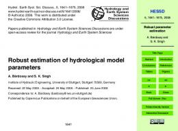
Figure 1: A time-varying structural system. Table 1: Time-varying system parameters. Property
Value
Mass (kg) Damping (N/(m/s))
𝑚1 = 0.5, 𝑚2 = 1.5, 𝑚3 = 1.0
5.2.1. The RPLR-FS-TARMA Method Based Estimation. The functional basis spanned by trigonometric functions of the form [11, 30]
𝑐2 = 0.5, 𝑐3 = 0.3
𝐺0 [𝑡] = 1,
𝑘1 = 300
Stiffness (N/m)
2𝜋𝑡 2𝜋𝑡 ) + 20 sin ( ) 170 85 2𝜋𝑡 2𝜋𝑡 𝑘3 (𝑡) = 120 + 72 sin ( ) + 24 sin ( ) 141.67 94.44 𝑘2 (𝑡) = 100 + 60 sin (
Downsizing: obtain Q# [𝑡] by removing the first 𝑁1 rows and columns of Q[𝑡] Compute Q# [𝑡]−1 according to Eq. (25) and (26) Downsizing: ̃ [𝑡] ← [Θ [𝑡 − 𝑁2 + 1] , Θ [𝑡 − 𝑁2 + 2] , . . . , Θ [𝑡]] Θ x̃ [𝑡] ← [x [𝑡 − 𝑁2 + 1] , x [𝑡 − 𝑁2 + 2] , . . . , x [𝑡]]
𝑇
(31)
Redefining: Q[𝑡] ← Q# [𝑡] end if
5. Numerical Validation 5.1. The Time-Varying Structural System. For validating the proposed method for output-only modal parameter recursive estimation of time-varying structures, the three-degree-offreedom structural system given by [11, 30] is used in this section, as shown in Figure 1. This system represents a simplified model of one-quarter of a truck vehicle [11, 30], which is subject to a unobservable, stationary, Gaussian, zero mean, and uncorrelated road excitation r(𝑡). The numerical values of system parameters are given in Table 1. Given a particular excitation realization, the vibration displacement responses for 𝑡 ∈ [−16.67, 850] s are obtained via the Runge-Kutta 4/5 method characterized by variable integration step and subsequently recorded at a sampling frequency 12 Hz [11, 30]. The initial 200 samples of the obtained responses for 𝑡 ∈ [−16.67, 0] s are discarded to minimize initialization effects. The rest of the obtained responses for 𝑡 ∈ [0, 850] s are corrupted by Gaussian white noise
𝐺2𝑘−1 [𝑡] = sin [
𝑘𝜋 (𝑡 − 1) ], 𝐿−1
𝑘𝜋 (𝑡 − 1) 𝐺2𝑘 [𝑡] = cos [ ], 𝐿−1
(32)
𝑘 = 1, 2, . . . , is selected. The corresponding dimensionalities and indices are, respectively, 𝑝𝑎 = 40, 𝑏𝑎 = [0 : 39], and 𝑝𝑐 = 6, 𝑏𝑐 = [0 : 5]. The value of 𝛾 = 10−4 is selected. Model order selection is achieved via the RSS criterion, as the RPLR-FSTARMA method is based on the class of recursive TARMA representations. Figure 2(a) depicts the RSS normalized by the sum of squares of the signal samples (series sum of squares, SSS) of the obtained RPLR-FS-TARMA (𝑝, 𝑞) (𝑝 = 𝑞 = 1, 2, 3, 4), which suggests AR order 𝑛𝑎 = 2. Figure 2(b) depicts the RSS normalized by the SSS of the obtained RPLRTARMA (𝑝, 𝑞) (𝑝 = 2, 𝑞 = 0, 1, 2), which suggests MA order 𝑛𝑐 = 2. Figure 3 depicts the “frozen-time” RPLR-FSTARMA based modal parameter estimates (with damping ratio 0 < 𝜁𝑖 [𝑡] < 0.1) from the 30 Monte Carlo tests, along with their theoretical counterparts. The blue dots notate the modal parameter estimates from the 30 tests, and the green dashed lines notate the theoretical modal parameters. 5.2.2. The Exponentially Weighted RPLR-TARMA Method Based Estimation. The functional basis given by (32) is selected with 𝑝𝑎 = 𝑝𝑐 = 1, 𝑏𝑎 = 𝑏𝑐 = 0. In other words, the exponentially weighted RPLR-FS-TARMA method reduces to its UPE counterpart, that is, the exponentially weighted RPLR-TARMA method. The values of 𝛾 = 10−4 and 𝜆 = 0.988 are selected. Figure 4(a) depicts the RSS normalized by the SSS of the obtained RPLR-TARMA (𝑝, 𝑞) (𝑝 = 𝑞 = 1, 2, 3, 4), which suggests AR order 𝑛𝑎 = 2. Figure 4(b) depicts the RSS normalized by the SSS of the obtained RPLRTARMA (𝑝, 𝑞) (𝑝 = 2, 𝑞 = 0, 1, 2), which suggests MA order 𝑛𝑐 = 2. Figure 5 depicts the “frozen-time” RPLR-TARMA based modal parameter estimates (with damping ratio 0