TKK Dissertations 119 Espoo 2008
FIXATION OF CARBON DIOXIDE BY PRODUCING CARBONATES FROM MINERALS AND STEELMAKING SLAGS Doctoral Dissertation Sebastian Teir
Helsinki University of Technology Faculty of Engineering and Architecture Department of Energy Technology
TKK Dissertations 119 Espoo 2008
FIXATION OF CARBON DIOXIDE BY PRODUCING CARBONATES FROM MINERALS AND STEELMAKING SLAGS Doctoral Dissertation Sebastian Teir
Dissertation for the degree of Doctor of Science in Technology to be presented with due permission of the Faculty of Engineering and Architecture for public examination and debate in Auditorium K216 at Helsinki University of Technology (Espoo, Finland) on the 2nd of June, 2008, at 12 noon.
Helsinki University of Technology Faculty of Engineering and Architecture Department of Energy Technology Teknillinen korkeakoulu Insinööritieteiden ja arkkitehtuurin tiedekunta Energiatekniikan laitos
Distribution: Helsinki University of Technology Faculty of Engineering and Architecture Department of Energy Technology P.O. Box 4400 FI - 02015 TKK FINLAND URL: http://eny.tkk.fi/ Tel. +358-9-451 3631 Fax +358-9-451 3418 E-mail:
[email protected] © 2008 Sebastian Teir ISBN 978-951-22-9352-0 ISBN 978-951-22-9353-7 (PDF) ISSN 1795-2239 ISSN 1795-4584 (PDF) URL: http://lib.tkk.fi/Diss/2008/isbn9789512293537/ TKK-DISS-2461 Picaset Oy Helsinki 2008
AB HELSINKI UNIVERSITY OF TECHNOLOGY P.O. BOX 1000, FI-02015 TKK http://www.tkk.fi
ABSTRACT OF DOCTORAL DISSERTATION Author Sebastian Teir
Name of the dissertation Fixation of carbon dioxide by producing carbonates from minerals and steelmaking slags Manuscript submitted
December 12th, 2007
Date of the defence
June 2nd, 2008
Manuscript revised
Monograph
March 31st, 2008
Article dissertation (summary + original articles)
Faculty
Faculty of Engineering and Architecture
Department
Department of Energy Technology
Field of research
Carbon dioxide capture and storage
Opponent(s)
Marco Mazzotti, Prof. and Olav Eklund, Prof.
Supervisor
Carl-Johan Fogelholm, Prof.
Instructor
Ron Zevenhoven, Prof.
Abstract Capture and storage of carbon dioxide (CO2) is internationally considered to be one of the main options for reducing atmospheric emissions of CO2. In Finland, no suitable geological formations are known to exist for storing captured CO2. However, fixing CO2 as solid carbonates using silicate-based materials is an interesting alternative. The magnesium silicate deposits in Eastern Finland alone could be sufficient for storing 10 Mt CO2 each year during a period of 200-300 years. Finnish steelmaking slags could also be carbonated, but the amounts produced provide a much smaller potential for CO2 storage (0.5 Mt CO2 per year) than magnesium silicates provide. The aim of this thesis was to study the possibility of reducing CO2 emissions by producing calcium and magnesium carbonates from silicate materials for the long-term storage of CO2 using multi-step processes. The production of carbonates from steelmaking slags and serpentinite, a magnesium silicate ore available from a metal-mining site, was studied both experimentally and theoretically. On the basis of the results, process concepts were developed and evaluated. Finally, the stability of synthetic calcium and magnesium carbonates as a medium for CO2 storage was assessed. Experiments with aqueous extraction and precipitation processes showed that magnesium and calcium can easily be extracted from steelmaking slags and natural silicate minerals using acids. Natural minerals seem to demand stronger acids for extraction than slags. Relatively pure calcium carbonate (80-90% calcite) was produced at room temperature and a CO2 pressure of 1 bar by adding sodium hydroxide to acetate solutions made from slag. Similarly, serpentinite was successfully converted into 93-100% pure hydromagnesite (a magnesium carbonate), using nitric acid or hydrochloric acid for the dissolution of serpentinite and sodium hydroxide for precipitation. The conversion of raw material to carbonate ranged from 60-90%. Although the results show that pure carbonates can be produced from industrial by-products and mining residues, the process concept suggested requires the recycling of large amounts of sodium hydroxide and acid, as well as low-grade heat for solvent evaporation. The methods suggested for recovering the spent chemicals were found to be expensive and cause more CO2 emissions than the amount of CO2 stored. Keywords
mineral carbonation, slag, carbon dioxide, dissolution, precipitation, carbonate
ISBN (printed)
978-951-22-9352-0
ISSN (printed)
1795-2239
ISBN (pdf)
978-951-22-9353-7
ISSN (pdf)
1795-4584
Language
English
Publisher
Helsinki University of Technology, Department of Energy Technology
Print distribution
Number of pages
106 p. + app. 93 p.
Helsinki University of Technology, Department of Energy Technology
The dissertation can be read at http://lib.tkk.fi/Diss/
AB TEKNISKA HÖGSKOLAN PB 1000, FI-02015 TKK http://www.tkk.fi
SAMMANFATTNING (ABSTRAKT) AV DOKTORSAVHANDLING Författare Sebastian Teir
Titel Bindning av koldioxid genom produktion av karbonater från mineraler och stålslagg Inlämningsdatum för manuskript 12.12.2007
Datum för disputation
2.6.2008
Datum för det korrigerade manuskriptet 31.3.2008 Monografi
Sammanläggningsavhandling (sammandrag + separata publikationer)
Fakultet
Fakulteten för ingenjörsvetenskaper och arkitektur
Institution
Institutionen för energiteknik
Forskningsområde Infångning och lagring av koldioxid Opponent(er)
Marco Mazzotti, Prof. och Olav Eklund, Prof.
Övervakare
Carl-Johan Fogelholm, Prof.
Handledare
Ron Zevenhoven, Prof.
Sammanfattning (Abstrakt) Infångning och lagring av koldioxid (CO2) anses på internationell nivå som en av de huvudsakliga alternativen för att minska på utsläppen av koldioxid till atmosfären. I Finland finns det inga kända geologiska formationer lämpliga för lagring av infångad koldioxid. Bindning av koldioxid som fasta karbonater genom användning av silikatbaserade material är emellertid ett intressant alternative. Magnesiumsilikatfyndigheterna i enbart Östra Finland kunde räcka till för att årligen lagra 10 Mt CO2 under en period på 200 – 300 år. Finsk stålslagg kunde också karboneras, men produktionsmängden kunde stå för en mycket mindre koldioxidlagringspotential (0.5 Mt CO2 per år) än vad magnesiumsilikaterna kunde stå för. Målsättningen för avhandlingen var att studera möjligheten att minska på koldioxidutsläppen genom att tillverka kalciumoch magnesiumkarbonater från silikatmaterial med flerstegsprocesser för långtidslagring av koldioxid. Tillverkningen av karbonater från stålslagg och serpentinit, en magenesiumsilikatmalm som är tillgänglig från en metallgruva, studerades experimentellt och teoretiskt. På basen av resultaten utvecklades och evaluerades ett processkoncept. Slutligen fastställdes stabiliten av syntetiska kalcium- och magnesiumkarbonater som koldioxidlagringsmedia. Experiment med vätskeutvinnings- och utfällningsprocesser visade att kalcium och magnesium kan lätt utvinnas från stålslagg och naturliga silikatmineraler genom att använda syror. Naturliga mineraler verkar kräva starkare syror för utvninning än vad slagg kräver. En rätt så ren kalciumkarbonat (80 – 90 % kalcit) fälldes ut vid rumstemperatur och 1 bar CO2 tryck genom att tillsätta natriumhydroxid till acetatlösningar tillverkade från slagg. På liknande vis konverterades serpentinite till 93 – 100 % ren hydromagnesit (en form av magnesiumkarbonat) genom att använda salpetersyra eller saltsyra för att lösa serpentiniten och natriumhydroxid för utfällningen. Konversionen från råmaterial till karbonat uppgick till 60 – 90 %. Fastän resultaten visar att ren karbonat kan produceras från industriella sidoprodukter och gruvdriftsresidual kräver processkonceptet återvinning av stora mängder av natriumhydroxid och syra samt lågkvalitetsvärme för förångning av lösningsmedel. Föreslagna metoder för återvinning av använda kemikalier konstaterades kostsamma och skulle ge upphov till mera koldioxidutsläpp än den lagrade mängden.
Ämnesord (Nyckelord)
mineralkarbonering, slagg, koldioxid, lösning, utfällning, karbonat
ISBN (tryckt)
978-951-22-9352-0
ISSN (tryckt)
1795-2239
ISBN (pdf)
978-951-22-9353-7
ISSN (pdf)
1795-4584
Språk
Engelska
Sidantal
106 p. + app. 93 p.
Utgivare
Tekniska högskolan, Institutionen för energiteknik
Distribution av tryckt avhandling
Tekniska högskolan, Institutionen för energiteknik
Avhandlingen är tillgänglig på nätet http://lib.tkk.fi/Diss/
Preface Before you continue to read this thesis, I would ask you to take time and reflect upon one of the most serious threats that mankind has ever created for itself. Human activities have released so much CO2 into the atmosphere that the current level has not been reached in the last 650,000 years, and still the emissions keep increasing. The latest reports from international experts stress the importance of stabilising our CO2 emissions within the next 20-30 years. The urgency of reducing our CO2 emissions has been my main motivation for carrying out this work. Considerable advances in technology for mitigating climate change are needed that will limit our CO2 emissions considerably. Recent research has also shown that reducing our carbon footprint now will cost us much less than trying to reduce it in 20-30 years’ time. Although global climate change is a serious threat, its mitigation is an important opportunity for global co-operation on a scale that has never been carried out before. We would save not only our environment but also our economy and our future. The work presented in this thesis was carried out in the framework of three projects: “Nordic CO2 sequestration” (NoCO2, 2003-2007), funded by Nordic Energy Research, as well as “CO2 Nordic Plus” (2003-2005) and “Slag2PCC” (2005-2007), funded by the Finnish Funding Agency for Technology and Innovation (TEKES), the Finnish Recovery Boiler Committee, Ruukki, UPM, and Wärtsilä. The projects were also supported by the Geological Survey of Finland, Outokumpu, Aker Kvaerner, Enprima, Foster-Wheeler Energy, Fortum, and Nordkalk. The Academy of Finland’s “ProDOE”-project (2007-2010) is also acknowledged for support during the final stages of writing this thesis. I also thank the Graduate School in Energy Technology for a scholarship during 2007, as well as the Walter Ahlström foundation, Vasa Nation, and the Foundation for Promotion of Technology (TES) for research grants. First, I want to thank Ron Zevenhoven and Carl-Johan Fogelholm for supervising my thesis work. I am grateful to them for the opportunity to work with such an interesting topic. I especially wish to thank my co-workers Sanni Eloneva, Hannu Revitzer, Justin Salminen, Tuulia Raiski and Jaakko Savolahti for their valuable assistance and discussions. I wish to thank Marco Mazzotti and Jarl Ahlbeck for providing statements for the pre-examination of my thesis. Thanks go also to Mika Järvinen for proof-reading my thesis. I would also like to thank Rein Kuusik, Mai Uibu, and Valdek Mikli at Tallinn University of Technology for assistance as well as for a very educational and productive visit at their university. Special thanks go to Pertti Kiiski, Vadim Desyatnyk, Loay Saeed, Seppo Markelin, and Taisto Nuutinen for technical assistance. Thanks also go to the rest of the personnel at the laboratory for contributing to the good spirit in the laboratory. I also want to thank Kari Saari for
iv
providing part of the equipment needed for the experiments and Rita Kallio for analysis services. I thank Soile Aatos, Peter Sorjonen-Ward and Olli-Pekka Isomäki for discussion and information about serpentinites. I also thank the people at Ruukki, Ovako, Outokumpu, Nordkalk, and Dead Sea Periclase for providing us with slag and mineral samples for our experiments. Special thanks also go to all my colleagues and friends in the projects. I thank my parents Mona-Lisa and Henrik, as well as my sister Sabina, for their love and the support they continue to give me, and my friends for giving me something else to think about. Finally, I want to thank Heidi for giving me her love, support, strength, uncompromised opinions, and inspiration.
Sebastian Teir Espoo, 21st April 2008
v
List of publications I.
TEIR, S., ELONEVA, S., ZEVENHOVEN, R., 2005. Production of precipitated calcium carbonate from calcium silicates and carbon dioxide. Energy Conversion and Management, 46, 2954-2979.
II.
TEIR, S., ELONEVA, S., FOGELHOLM, C.-J., ZEVENHOVEN, R., 2007. Dissolution of Steelmaking Slags in Acetic Acid for Precipitated Calcium Carbonate Production. Energy, 32(4), 528-539.
III.
ELONEVA, S., TEIR, S., SAVOLAHTI, J., FOGELHOLM, C.-J., ZEVENHOVEN, R., 2007. Co-utilisation of CO2 and Calcium Silicate-rich Slags for Precipitated Calcium Carbonate Production (Part II). In: Proceedings of ECOS 2007, Padua, Italy, 25-28 June 2007, Volume II, 1389-1396 (submitted in a reworked form to Energy, March 2007).
IV.
TEIR, S., REVITZER, H., ELONEVA, S., FOGELHOLM, C-J., ZEVENHOVEN, R., 2007. Dissolution of natural serpentinite in mineral and organic acids. International Journal of Mineral Processing, 83(1-2), 36-46.
V.
TEIR, S., KUUSIK, R., FOGELHOLM, C.-J., ZEVENHOVEN, R., 2007. Production of magnesium carbonates from serpentinite for long-term storage of CO2. International Journal of Mineral Processing, 85(1-3), 1-15.
VI.
TEIR, S., ELONEVA, S., FOGELHOLM, C-J., ZEVENHOVEN, R., 2007. Carbonation of minerals and industrial by-products for CO2 sequestration. In: Proceedings of IGEC-III, 2007. The Third International Green Energy Conference. June 17-21, 2007, Västerås, Sweden. ISBN: 978-91-85485-53-6 (CD-ROM) (a reworked version of this paper has been accepted for publication in Applied Energy, March 2008)
VII. TEIR, S., ELONEVA, S., FOGELHOLM, C-J., ZEVENHOVEN, R., 2006. Stability of Calcium Carbonate and Magnesium Carbonate in Rainwater and Nitric Acid Solutions. Energy Conversion and Management, 47, 3059-3068.
vi
The author’s contribution to the appended publications I.
Sebastian Teir was responsible for planning and performing the process modelling and calculation work. The author also carried out half of the literature review, while the other half was carried out by Sanni Eloneva. The author was also responsible for the interpretation of the results and writing the paper.
II.
Sebastian Teir planned and carried out the experiments, as well as the interpretation of the results, in collaboration with Sanni Eloneva. Sebastian Teir carried out the thermodynamic calculations and wrote most of the article.
III.
Sebastian Teir planned and carried out the experiments in collaboration with Sanni Eloneva and assisted her with the interpretation of the results.
IV.
Sebastian Teir was responsible for all the experimental work except for the solvent selection experiment series, which was carried out by Hannu Revitzer. Sebastian Teir was responsible for planning the research, the experimental design, the interpretation of the results, performing the kinetic analysis, and writing the paper.
V.
Sebastian Teir was responsible for planning the research, the experimental design, performing the experiments, the interpretation of the results, and writing the paper.
VI.
Sebastian Teir was responsible for the process evaluation, the interpretation of the TGA analysis results, and writing the paper.
VII. Sebastian Teir planned and carried out the experiments, as well as the interpretation of the results, in collaboration with Sanni Eloneva. Sebastian Teir wrote most of the article and carried out all the thermodynamic calculations.
vii
Table of contents Abstract .................................................................................................................................... iii Preface ...................................................................................................................................... iv List of publications ................................................................................................................... vi The author’s contribution to the appended publications.......................................................... vii Table of contents .................................................................................................................... viii Nomenclature ............................................................................................................................ x 1
Introduction ....................................................................................................................... 1 1.1
Capture and storage of CO2 ....................................................................................... 2
1.2
Mineral carbonation................................................................................................... 6
2
Objective of this thesis ...................................................................................................... 8
3
Literature review ............................................................................................................. 10 3.1
3.1.1
Natural calcium silicates.................................................................................. 11
3.1.2
Natural magnesium silicates............................................................................ 12
3.1.3
Alkaline solid waste materials......................................................................... 14
3.2
Carbonation processes ............................................................................................. 16
3.2.1
Weathering of rocks ........................................................................................ 17
3.2.2
Direct carbonation ........................................................................................... 18
3.2.3
Indirect carbonation......................................................................................... 21
3.2.4
Carbonation of industrial residues and by-products ........................................ 27
3.2.5
Production of precipitated calcium carbonate ................................................. 29
3.3 4
Suitable raw materials ............................................................................................. 10
Utilisation of carbonate products............................................................................. 31
Production of PCC from calcium silicates – concept and potential ................................ 33 4.1
Process comparison and evaluation ......................................................................... 33
4.1.1
PCC production from limestone ...................................................................... 33
4.1.2
Calcium carbonate production by indirect carbonation of calcium silicate using
hydrochloric acid ............................................................................................................. 35 4.1.3
Calcium carbonate production by indirect carbonation of calcium silicate using
acetic acid ........................................................................................................................ 36
5
4.2
Potential................................................................................................................... 37
4.3
Discussion................................................................................................................ 40
Production of calcium carbonate from steelmaking slag................................................. 41 5.1
Thermodynamic calculations................................................................................... 41
5.1.1
Equilibrium of reaction equations ................................................................... 41
viii
6
5.1.2
Dissolution of blast furnace slag ..................................................................... 42
5.1.3
Carbonation of calcium-rich solution of acetic acid........................................ 43
5.2
Characterisation of materials ................................................................................... 44
5.3
Dissolution of steelmaking slags ............................................................................. 45
5.4
Precipitation of carbonates ...................................................................................... 49
5.4.1
Carbonation of dissolved blast furnace slag .................................................... 49
5.4.2
Carbonation of acetates derived from blast furnace slag................................. 50
5.5
Process evaluation ................................................................................................... 54
5.6
Discussion................................................................................................................ 57
Production of magnesium carbonate from serpentinite ................................................... 59 6.1
Characterisation of serpentinite ............................................................................... 59
6.2
Selection of solvent ................................................................................................. 60
6.3
Effect of concentration, temperature, and particle size on dissolution of serpentinite 61
7
8
6.4
Dissolution kinetics ................................................................................................. 63
6.5
Precipitation of carbonates ...................................................................................... 68
6.6
Process evaluation ................................................................................................... 71
6.7
Discussion................................................................................................................ 75
Stability of calcium carbonate and magnesium carbonate .............................................. 77 7.1
Stability of carbonates in rainwater and solutions of nitric acid.............................. 78
7.2
Stability of synthetic hydromagnesite ..................................................................... 79
7.3
Discussion................................................................................................................ 80
Conclusions ..................................................................................................................... 82 8.1
Significance of this work......................................................................................... 84
8.2
Recommendations for future work .......................................................................... 85
References ............................................................................................................................... 86
ix
Nomenclature Abbreviations
AAS
Atomic absorption spectrophotometry
AOD
Argon-oxygen decarburisation
BOF
Basic oxygen furnace
CCS
Carbon dioxide capture and storage
EAF
Electric arc furnace
ECBM
Enhanced coal bed methane recovery
EOR
Enhanced oil recovery
FT-IR
Fourier transform – infrared spectroscopy
ICP-AES
Inductively coupled plasma – atomic emission spectrometry
PCC
Precipitated calcium carbonate
SEM
Scanning electron microscope
TC
Total carbon content
TGA
Thermogravimetric analysis
TOC
Total organic carbon content
XRD
X-Ray diffraction
XRF
X-Ray fluorescence
Chemical compounds, minerals and rocks
Al2O3
Aluminum oxide
Ca(CH3COO)2
Calcium acetate
CaCl2
Calcium chloride
CaCO3
Calcium carbonate (calcite, aragonite, vaterite); limestone
CaO
Calcium oxide; lime
Ca(OH)2
Calcium hydroxide; hydrated lime
CaSiO3
Calcium metasilicate; wollastonite
CH3COOH
Acetic acid
CH3COONa
Sodium acetate
CO2
Carbon dioxide
EDTA
Ethylenediaminetetraacetic acid
FeCO3
Iron (II) carbonate; siderite
Fe2O3
Iron (III) oxide; hematite
x
Fe3O4
Iron (III) oxide; magnetite
Fe2SiO4
Iron (II) orthosilicate; fayalite
HCl
Hydrochloric acid
H2CO3
Carbonic acid
HCOOH
Formic acid
HF
Hydrofluoric acid
HNO3
Nitric acid
H2SO4
Sulphuric acid
KOH
Potassium hydroxide
Mg(CH3COO)2
Magnesium acetate
MgCl2
Magnesium chloride
MgCl2·6H2O
Magnesium chloride hexahydrate
MgCO3
Magnesium carbonate; magnesite
MgCO3·3H2O
Magnesium carbonate trihydrate; nesquehonite
MgCO3·5H2O
Magnesium carbonate pentahydrate; lansfordite
Mg5(CO3)4(OH)2·4H2O Magnesium carbonate; hydromagnesite Mg(NO3)2
Magnesium nitrate
Mg(NO3)2·6H2O
Magnesium nitrate hexahydrate
MgO
Magnesium oxide; periclase
Mg(OH)2
Magnesium hydroxide; brucite
Mg(OH)Cl
Magnesium hydroxide chloride
MgSO4
Magnesium sulphate
MgSiO3
Magnesium metasilicate; enstatite
Mg2SiO4
Magnesium orthosilicate; olivine (fosterite)
Mg3Si2O5(OH)4
Serpentine (chrysotile, lizardite, antigorite)
NH3
Ammonia
NH4Cl
Ammonium chloride
NH4NO3
Ammonium nitrate
NH4OH
Ammonium hydroxide
(NH4)2SO4
Ammonium sulphate
(NH4)2CO3
Ammonium carbonate
NaCl
Sodium chloride
Na2CO3
Sodium carbonate
NaHCO3
Sodium bicarbonate
NaNO3
Sodium nitrate
NaOH
Sodium hydroxide; caustic soda
SiO2
Silicon dioxide; silica xi
Symbols
b
Stoichiometric coefficient
[-]
Ci
Molar concentration of i
[mol cm-3]
De
Effective diffusion coef. in a porous structure
[cm2 s-1]
E
Activation energy
[kJ mol-1]
∆G
Gibbs energy change
[kJ mol-1]
∆H
Reaction enthalpy
[kJ mol-1]
k
Reaction rate constant
[s-1]
k0
Frequency factor
[s-1]
K
Thermodynamic equilibrium constant
[-]
Q
Heat demand
[J]
P
Power demand
[J]
n
Amount of species
[mol]
ρ
Molar density
[mol cm-3]
r
Radius of particle
[cm]
R
Ideal gas constant: 8.3145
[ J K-1 mol-1]
R2
Multiple regression correlation coefficient
[-]
t
Reaction time
[s]
T
Temperature
[K]
V
Volume
[l]
Xi
Conversion of i
[-]
xii
1 Introduction Since the mid-19th century, the global average surface temperature has increased by almost one degree Celsius, which is likely to be the largest increase in temperature during the past 1300 years (IPCC, 2007). Eleven of the last twelve years (1995-2006) were among the 12 warmest years since 1850. A few of the visible impacts of climate change are the widespread retreat of mountain glaciers, the rise in the global average sea level, and the increasing frequency and intensity of droughts in recent decades. While natural changes in the climate are common, it is now very likely that human activities have attributed significantly to the warming of the climate since the year 1750. Certain gases in the atmosphere, mainly carbon dioxide (CO2) and water vapour, trap infrared (heat) radiation from the Earth’s surface, while letting solar radiation pass through. This heat-trapping mechanism, called the natural greenhouse effect, helps to keep the Earth’s surface temperature, which otherwise would be around -19 °C, at an average of 14 °C. However, during the last two centuries the concentration of greenhouse gases (most importantly CO2, but also methane, nitrous oxide, and fluorinated gases) and aerosols in the atmosphere has increased drastically as a result of human activities. According to data collected from ice cores, the current atmospheric concentration of CO2 (380 ppm) exceeds by far the natural range over the last 650,000 years (180 to 300 ppm) (IPCC, 2007). Emissions of greenhouse gases are expected to continue to rise and strengthen the greenhouse effect, which is projected to lead to a rise in the average temperature of 1-6 °C during the next century (IPCC, 2001b). The main source of anthropogenic CO2 emissions (about three-quarters) is the combustion of fossil fuel. The rest is mainly due to land use changes, especially deforestation. Several industrial processes (such as oil refining and the manufacturing of cement, lime, and steel) are also significant sources of CO2. The annual anthropogenic CO2 emissions are currently about 26 Gt1 CO2 (IPCC, 2007). Significant technological developments in reducing greenhouse gas emissions have been achieved during recent decades. Technological options for the reduction of emissions include more effective energy use, improved energy conversion technologies, a shift to low-carbon or renewable biomass fuels, a shift to nuclear power, zero-emissions technologies, improved energy management, the reduction of industrial by-product and process gas emissions, and carbon capture and storage (IPCC, 2001a). However, according to IPCC, none of these options alone can achieve the required reductions in greenhouse gas emissions. Instead, a
1
1 Gt = 1,000 Mt = 1,000,000 kt = 1,000,000,000 tonne
1
combination of these mitigation measures will be needed to achieve a stabilisation of the greenhouse gas concentration in the atmosphere. According to the commitments under the 1997 Kyoto Protocol, industrial countries should reduce their greenhouse gas emissions by an average of 5% from their 1990 levels during 2008-2012 (Ministry of the Environment, 2001). The Kyoto protocol binds Finland to reduce its greenhouse emissions to their 1990 level (77.1 Mt CO2 equivalent, excluding land use changes and forestry). According to the Ministry of Trade and Industry (2005), the permitted emission limit is likely to be exceeded by 15%, approximately 11 Mt per year, during the Kyoto protocol period 2008-2012.
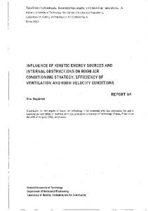
1.1 Capture and storage of CO2 Carbon dioxide capture and storage (CCS; CO2 sequestration) is considered to be one of the main options for reducing CO2 emissions caused by human activities. The concept of CCS includes the collection and concentration of CO2 produced by an industrial or energy-related source (referred to as CO2 capture), the transportation of CO2 to a suitable storage location, and the storage of CO2 in isolation from the atmosphere. CCS would significantly reduce current CO2 emissions, allowing fossil fuels to continue to be used in the future. The purpose of CO2 capture is to produce a concentrated stream of CO2 at high pressure that can be transported to a storage site (IPCC, 2005). For the energy sector, there are three main approaches to capturing the CO2 generated from fossil fuels, biomass, or mixtures of these fuels, depending on the process or power plant application to which CO2 capture is applied: post-combustion, pre-combustion, and oxy-fuel combustion systems (Figure 1.1). Post-combustion systems separate CO2 from a flue gas stream2, typically using a liquid solvent such as monoethanolamine. It is used for absorbing CO2 from part of the flue gases from a number of existing power plants. It is also in commercial use in the natural gas processing industry. Pre-combustion systems remove CO2 before combustion by employing gasification, water-shifting, and CO2 separation. This technology is widely applied in fertiliser manufacturing and in hydrogen production. Oxy-fuel combustion systems use oxygen, instead of air, for the combustion of the primary fuel to produce a flue gas that consists mainly of water vapour and CO2. This relatively new technology requires the production of pure oxygen from air and results in a flue gas with high CO2 concentrations from which the water vapour is removed by condensation. The main challenge for the development of CO2 capture technology is to reduce the energy requirements of the capture processes. The energy needed for capturing 90% of the CO2 from a power plant increases the fuel consumption per unit of electricity produced by 2
Flue gases from power plants burning fossil fuel typically contain 3-15 vol-% CO2.
2
11-40% (using the best current technology compared to power plants without capture; IPCC, 2005). Therefore, CO2 capture also increases the cost of electricity production by 35-85% (Table 1.1). N2, O2, H2O Fuel Air
Power Power&&heat, heat, Industrial process Industrial process
Air / O2, steam Fuel
CO2
Flue gas CO separation CO2 2separation
CO, H2 Gasification Gasification
Reformer + CO2 Reformer + CO2 separation separation
Air
Power Power&&heat heat
O2 Air Airseparation separation
N2
CO CO2 2dehydration, dehydration, compression, compression, transport and transport and storage storage
H2
N2
Air
CO2
N2, O2, H2O
CO2, H2O Power Power&&heat heat CO2, H2O recycle
Figure 1.1. Options for capturing CO2 from power plants.
The separated CO2 must, in most cases, be transported to the storage site, since suitable storage sites are seldom located near the CO2 source (IPCC, 2005). Transportation by pipelines is a mature technology, which has been in use for enhanced oil recovery since the 1970s. To avoid pipe corrosion the gas cannot contain any free water and must therefore be dehydrated before transportation. Transportation by ship or road and rail tankers is also possible. Gaseous CO2 is typically compressed for transportation to a pressure above 80 bar in order to avoid two-phase flow regimes and increase the density of the CO2, thereby making it easier and less costly to transport. The cost of pipeline transport is dependent on the flow rate, terrain, offshore/onshore transportation, and distance. For a nominal distance of 250 km the cost is typically 1-8 US$/tCO2. In order for CCS to be a useful option for reducing CO2 emissions, the captured CO2 has to be stored for a long period of time, for at least thousands of years, in isolation from the atmosphere (IPCC, 2005). Currently, the only technology that has reached demonstration level for accomplishing this on a sufficiently large scale is the use of underground geological formations for the storage of CO2. Nearly depleted or depleted oil and gas reservoirs, deep
3
saline formations, and unminable coal beds are the most promising options for the geological storage of CO2. Suitable storage formations can occur in both onshore and offshore sedimentary basins (natural large-scale depressions in the Earth's crust that are filled with sediments). In each case, CO2 is injected in compressed form into a rock formation at depths greater than 800 m, where the CO2 is in a liquid or supercritical state because of the ambient pressures. To ensure that the CO2 remains trapped underground, a well-sealed cap rock is needed over the selected storage reservoir. The geochemical trapping of CO2 (i.e. fixation as carbonates) will eventually occur as CO2 reacts with the fluids and host rock in the reservoir, but this happens on a time scale of hundreds to millions of years. In order to minimise the risk of CO2 leakage, the storage sites must be monitored for a very long time. Currently, there are several projects running that demonstrate this technology. The injection of CO2 into geological formations involves many of the same technologies that have been developed in the oil and gas exploration and production industry. 30 Mt of CO2 is injected annually for enhanced oil recovery (EOR), mostly in Texas, USA, where EOR has been used since the early 1970s. However, most of this CO2 is obtained from natural CO2 reservoirs. At the moment three industrial-scale projects are storing 3-4 Mt of CO2 annually in saline aquifers. The estimated total CO2 storage capacity for geological formations worldwide is 2,000-10,000 Gt of CO2, while the costs of storage in saline formations and depleted oil and gas fields have been estimated to be 0.5-8 US$/tCO2 injected, with an additional cost for monitoring3 of 0.10.3 US$/tCO2 (Table 1.1). Another option for storing CO2 is to inject CO2 directly into the deep ocean at depths greater than 1000 m. This option is not a mature technology but has been under research for several decades. CO2 can be transported via pipelines or ships to an ocean storage site, where it is either injected directly into the ocean or deposited into a CO2 lake on the sea floor4. The analysis of ocean observations and models both indicate that injected CO2 will be isolated from the atmosphere for at least several hundred years, and that the fraction retained tends to be higher with deeper injection. The cost of injecting CO2 into the ocean at 3000 m has been estimated at 5-30 US$/tCO2 (Table 1.1). However, actively injecting CO2 may have harmful effects on the ocean environment, about which little is known. Experiments show that adding CO2 can harm marine organisms, but it is still unclear what effects the injection of several million tonnes of CO2 would have on ocean ecosystems.
3
A scenario analysed in IEA (2007) for cost estimations, however, considers only 20 years of
monitoring after 30 years of injection in a saline aquifer. 4
Such CO2 lakes must be situated deeper than 3 km below the ocean surface where CO2 is denser than
sea water.
4
From Finland’s perspective CCS does not provide an easy answer to reducing CO2 emissions, since the Finnish bedrock is not suitable for the basin sequestration of CO2. The offshore oil and gas fields and saline aquifers located in the North Sea and Barents Sea appear to be the closest suitable CO2 sequestration sites. The distances to these sites are approximately 500-1000 km (Koljonen et al., 2004). Currently, the only known domestic large-scale CO2 storage alternative for Finland is mineral carbonation, because of the availability of widespread deposits of the mineral needed for the carbonation process.
Table 1.1. Cost ranges for the components of large-scale CCS systems (IPCC, 2005). CCS system components
Cost range
Remarks
Capture from a coal- or gas-
15-75 US$/tCO2 net captured
Net costs of captured CO2,
fired power plant
compared to the same plant without capture.
Capture from hydrogen and
5-55 US$/tCO2 net captured
Applies to high-purity sources
ammonia production or gas
requiring simple drying and
processing
compression.
Capture from other industrial
25-115 US$/tCO2 net captured
Range reflects use of a number of different technologies and
sources
fuels. 1-8 US$/tCO2 transported
Transportation
Per 250 km pipeline or shipping for mass flow rates of 5 (high end) to 40 (low end) MtCO2/a.
a
Geological storage
0.5-8 US$/tCO2 net injected
Excluding potential revenues from EOR or ECBM.
Geological storage: monitoring
0.1-0.3 US$/tCO2 injected
This covers pre-injection, injection, and post-injection
and verification
monitoring, and depends on the regulatory requirements. Ocean storage
5-30 US$/tCO2 net injected
Including offshore transportation of 100-500 km, excluding monitoring and verification.
Mineral carbonation
50-100 US$/tCO2 net
Range for the best case studied.
mineralised
Includes additional energy use for carbonation.
a
In the long term, there may be additional costs for remediation and liabilities.
5
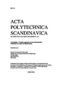
1.2 Mineral carbonation CO2 could be stored in the form of solid inorganic carbonates by means of chemical reactions. Calcium and magnesium carbonates are formed in nature by a process known as the weathering of rocks. In this natural process calcium and magnesium ions are leached out of silicate rocks by rivers and rainfall and react with CO2, forming solid calcium and magnesium carbonates. The concept of an accelerated carbonation process for the storage of CO2 is commonly referred to as mineral carbonation. The metal oxides in silicate rocks that can be found in the Earth’s crust could in theory bind all the CO2 that could be produced by the combustion of all available fossil fuel reserves (Figure 1.2). Alkaline industrial wastes and by-products, such as steelmaking slags and process ashes, also have high contents of magnesium and calcium, but their CO2 storage capacity is much more limited. Mineral carbonation produces silica (SiO2) and carbonates that are environmentally stable and can therefore be disposed of as mine filler materials or used for construction purposes. Magnesium carbonates (MgCO3) and calcium carbonates (CaCO3, limestone) are already plentiful in nature and are known to be sparingly soluble salts (Lackner, 2002). Since carbonation securely traps CO2, there would be little or no need to monitor the disposal sites
1000000 Mineral carbonation
10000
Underground injection
EOR 1000
Ocean acidic
Fossil carbon
Ocean neutral
Annual emission
Charasteristic storage time (years)
100000
100
10
1 1
10
100
1000
10000
100000
1000000
10000000
Carbon storage capacity (Gt)
Figure 1.2. Estimated storage times and capacities for various CO2 storage methods (after Lackner, 2003).
6
and the environmental risks would be very low (IPCC, 2005). The overall carbonation chemistry using calcium or magnesium silicates is presented in Equation 1:
(Mg, Ca) x Si y O x + 2y + z H 2z (s) + xCO 2 (g) → x(Mg, Ca)CO 3 (s) + ySiO 2 (s) + zH 2 O
(1)
Apart from the large and safe storage capacity, the exothermic nature of the overall carbonation reaction is another benefit of mineral carbonation which motivates further research. The natural carbonation of silicate materials is very slow, which means that the carbonation must be accelerated considerably to be a viable large-scale storage method for captured CO2. Therefore, research in the field of mineral carbonation is focused on developing accelerated carbonation processes that are also energy-efficient. Additional requirements for a commercial CO2 storage process by mineral carbonation are the mining, crushing, and milling of the mineral-bearing ores and their transportation to a processing plant that has access to a concentrated CO2 stream from a capture plant. Accelerated carbonation technology for natural minerals is still in the development stage and is not yet ready for implementation. The best case studied so far is the wet carbonation of natural silicate olivine (Chapter 3.2.2.2), for which the estimated process costs are 50-100 US$ per tonne of net CO2 carbonation, excluding CO2 capture and transport costs (Gerdemann et al., 2007). The energy requirements of this carbonation process are typically 30-50% of the output of the power plant from which CO2 is captured. In combination with the power requirements of the capture facility, up to 60-180% more energy input is required per kilowatt-hour produced than for a power plant without CCS. The carbonation process would require 2-4 tonnes of silicates per tonne of CO2 to be mined and produce 3-5 tonnes of material to be disposed of per tonne of CO2 stored as carbonates, which will have a similar environmental impact to current largescale surface mining operations (IPCC, 2005).
7
2 Objective of this thesis The main challenge for using mineral carbonation for CO2 sequestration is to develop an economically feasible process. To achieve this, economic and rapid methods for extracting reactive magnesium or calcium compounds (such as oxides, hydroxides, or base ions) from the rock and for carbonating these must be developed. An implemented carbonation process for CO2 sequestration would be on the scale of an average-sized open mining facility, because of the large amounts of minerals required. Therefore, besides providing rapid conversion, the carbonation process must also convert as much as possible of the minerals to carbonates, in order for the environmental impact to be minimal. An important aspect of mineral carbonation is the end-use or disposal of the carbonate product. Using mineral carbonation for sequestering CO2, the material amounts of carbonates, silica, and other compounds (depending on the raw material used) from such a process would be huge: sequestering 1 Mt of CO2 produces 2.3 Mt of CaCO3 or 1.9 Mt of MgCO3 (assuming a conversion efficiency of 100%) with various amounts of silica and other by-products, depending on the raw material used. Therefore, it is very important to be able to utilise these products as much as possible. Although the end-products of a carbonation process for CO2 storage would eventually exceed the market demand, the possibility of selling them could help to introduce a technology infrastructure for mineral carbonation and develop it into a feasible CO2 storage technology. The technology for producing synthetic calcium carbonate from limestone is known and used on an industrial scale, but the carbonation of silicate minerals requires other processes than those used for limestone carbonation. While the direct carbonation of magnesium silicates and calcium silicates has been comprehensively studied, most of these processes produce an aqueous slurry of carbonates, unreacted silicates, silica, and other by-products, from which it is difficult to separate the individual components (O’Connor et al., 2005; Huijgen et al., 2006). Indirect (or multi-step) processes, such as those suggested by Lackner et al. (1995) and Kakizawa et al. (2001), allow for the separation of silica and other by-products, such as metals and minerals, before the carbonation step. An indirect process is therefore a better alternative for producing separate streams of carbonates and other materials for further recovery. The present work shows that industrial wastes and by-products can be converted into more valuable products using indirect carbonation processes. However, very little in the way of experimental data on these processes can be found in the literature. The relatively high price of precipitated calcium carbonate (over ten times that of raw limestone or steelmaking slag products) could justify the development of a carbonation process with high running costs.
8
However, the purity and crystal structure of the synthetic carbonate and other products of such a process determine their value. The objective of this thesis was to study the possibility and potential of producing relatively pure calcium and magnesium carbonates from silicate materials for the long-term storage of CO2 using indirect processes. The research tasks for achieving this were: i.
Evaluate the CO2 emission reduction potential by producing precipitated calcium carbonate from calcium silicates instead of limestone (Paper I).
ii. Study the possibility of producing calcium carbonates from steelmaking slags for the reduction of CO2 emissions by experimental and theoretical research (Papers II-III). iii. Study the possibility of producing magnesium carbonates from serpentinite for the sequestration of CO2 by experimental and theoretical research (Papers IVVI). iv. Evaluate the stability of synthetic magnesium and calcium carbonates as a medium for CO2 storage (Papers VI-VII).
Processes for calcium silicate carbonation suggested in the literature were studied by process modelling and their energy use and net potential for CO2 fixation were evaluated. An acetic acid process appeared to be the most promising of the systems studied for the carbonation of calcium silicates. Since natural calcium silicate mineral resources were found to be scarce, the use of steelmaking slags for carbonate production was investigated by means of experiments and theoretical calculations. The large resources of magnesium silicates justified the systematic development of an indirect process for converting magnesium silicates into magnesium carbonates. Finally, the stability of magnesium carbonate and calcium carbonate as a medium for CO2 storage was evaluated.
9
3 Literature review The purpose of this literature review was: •
To select raw materials potentially suitable for carbonation and readily available in Finland.
•
To review the most comprehensively studied carbonation routes proposed in the literature, as well as the processes that are relevant for this work.
•
To discuss potential markets and uses for the carbonates produced.
3.1 Suitable raw materials In order to provide for significant storage of CO2, large amounts of raw materials are required as feedstock for carbonation. Therefore, the raw materials used for carbonation must be abundant and cheap. From a chemical elements perspective, both alkali (e.g. Na, K, etc.) and alkaline earth (e.g. Ca, Mg) metals can be carbonated (Huijgen and Comans, 2003; 2005). However, alkali metals are unsuitable for the long-term storage of CO2, since alkali (bi)carbonates are soluble in water, which could release CO2 back into the atmosphere. Additionally, a number of other metals (e.g., Mn, Fe, Co, Ni, Cu, and Zn) could potentially be carbonated, but most of these elements are either too rare or too valuable to be used for the sequestration of CO2. Of the alkaline earth metals, magnesium and calcium are by far the most common in nature. The Earth’s crust consists of roughly 2 mol-% magnesium and 2 mol-% calcium, primarily bound as carbonates and silicate minerals (Goff and Lackner, 1998; Brownlow, 1996). In order to minimise the amount of raw material needed, materials with high concentrations of calcium and magnesium should be favoured, while materials already containing significant concentrations of carbonates should be avoided. From this perspective, magnesium and calcium oxides or hydroxides would be ideal materials, but these are rare in nature. Calcium silicates and magnesium silicates are particularly suitable for carbonation, since these materials are abundant in the Earth’s crust. The storage capacity of silicate minerals has been estimated at 10,000-10,000,000 Gt of carbon (Figure 1.2), which exceeds the amount of carbon in known fossil fuel resources. Although calcium silicates tend to be more reactive for carbonation than magnesium silicates, calcium silicates with high concentrations of calcium are relatively rare (Lackner, 2002). The Finnish bedrock consists locally of rock types that contain an abundance of Mg and Ca silicates, such as serpentine, pyroxenes, amphiboles, and talc, which could be suitable for carbonation (Teir et al., 2006a). Several industrial residues and by-products, such as iron and steel slags, various process
10
ashes, and cement-based materials can have high concentrations of calcium and magnesium. Although the amounts of by-products and residues are much smaller than natural resources, by-products and residues are readily available, continuously produced, and tend to be more reactive than natural minerals. 3.1.1
Natural calcium silicates A suitable source of natural calcium silicate is wollastonite, CaSiO3, which has a
relatively high calcium content (48 wt-% CaO). Wollastonite is mainly found with crystalline limestone occurrences, since it has been formed in nature from the interaction of calcite (CaCO3) with silica (SiO2) under high temperatures and pressures. Wollastonite is used in the plastic, ceramic, and metallurgical industries as a filler and additive for various applications. For wollastonite, the carbonation reaction5 can be written as
CaSiO 3 (s) + CO 2 (g) → CaCO 3 (s) + SiO 2 (s),
∆H = −89 kJ/mol CO 2
(2)
Wollastonite deposits of economic value are rare. Although wollastonite is common, especially in limestone in the southern part of Finland, the mineral does not form economically interesting deposits in most of its occurrences (Eskola et al., 1929; Dahlberg, 2004). The worldwide production of wollastonite was estimated to be between 550 and 600 kt in 2003, of which Finland, as a major wollastonite supplier, produced slightly less than 20 kt (USGS, 2003). The price of wollastonite on the international market in 2002 ranged from 50 US$/t for lump wollastonite to 1700 US$/t for ultra-fine surface-treated wollastonite. Finnish fine-grain wollastonite can be obtained for 200 €/t. As a comparison, the average price for lime (CaO) was 63 US$/t (USGS, 2003). The average composition of Finnish wollastonite can be found in Table 3.1. Basalt rocks are also rich in calcium oxides and could therefore provide a feedstock for mineral carbonation. Basalt is the most common igneous rock and is found widely distributed throughout the world. Basalt has an average CaO content of 10 wt-%, but also contains iron (8 wt-% Fe) and magnesium (7 wt-% MgO) that could be carbonated (Table 3.1). In a recent study by McGrail et al. (2006), the potential for in situ carbonation (see Chapter 3.2) of flood basalts was estimated at 100 Gt of CO2 in the eastern part of the U.S. alone. In Finland, all igneous rocks are metamorphosed and basalt does not exist as such. In northern Finland and Karelia, igneous rocks are metamorphosed from basalt, with the main 5
All enthalpy differences are calculated at 25 °C using Outokumpu HSC 5.1 with additional
thermodynamic data for MgO, Mg(OH)2, and MgCO3 from Robie et al. (1978) unless supplementary text specifies otherwise.
11
minerals being amphibole, plagioclase, and sometimes chlorite, with a CaO content of 7-9 wt% (GSF, 2004).
Table 3.1. Examples of the composition of wollastonite and basalt (units: wt-%). CaO
SiO2
MgO
Al2O3
Fe
Ti
Mn
Wollastonitea
44
no data
no data
no data
0.1
no data
no data
b
9.5
49
6.7
16
8.2
1.1
0.2
Basalt a
Data from Dahlberg (2004).
b
Data from Cox et al. (1979).
3.1.2
Natural magnesium silicates Since magnesium silicate rocks are usually richer in base ions than calcium silicate
rocks (Lackner, 2002), most of the research into mineral carbonation has focused on the carbonation of olivine (Mg2SiO4; Equation 3) and serpentine (Mg3Si2O5(OH)4; Equation 4).
Mg 2SiO 4 (s) + 2CO 2 (g) → 2MgCO 3 (s) + SiO 2 (s), ∆H = −90 kJ/mol CO 2 Mg 3Si 2 O 5 (OH) 4 (s) + 3CO 2 (g) → 3MgCO 3 (s) + 2SiO 2 (s) + 2H 2 O(l), ∆H = −64 kJ/mol CO 2
(3) (4)
Suitable magnesium-rich, ultramafic rocks are distributed throughout the world. The amount of Mg in the Earth’s crust (2.0 mol-%) is almost 60 times larger than the amount of C (0.035 mol-%). For instance, the large dunite body at Twin Sisters, Washington, U.S., could store almost 100 Gt of CO2, which amounts to about 19 years’ worth of U.S. CO2 emissions (Goff and Lackner, 1998). The most common Finnish Mg rich rocks are ultramafic intrusive or extrusive rocks, i.e. peridotites, dunites, hornblendites, pyroxenites, and komatiites, and their metamorphic varieties, i.e. serpentinites, talc, and asbestos rocks. Of these ultramafic rocks, the most interesting for CCS purposes are the serpentinites, because they consist mainly of serpentine (Table 3.2). A detailed survey of Finnish ultramafic rocks suitable for carbonation has recently been made by Aatos et al. (2006). Millions of tons of poorly documented in situ or hoisted serpentinite or tailed serpentine deposits are situated mainly in central Finland. It has been estimated that in Eastern Finland alone there are about 121 km2 of serpentinites. The effective sequestering capacity of these serpentinites is not known because of the considerable variation in the amount of pure serpentine in different serpentinite formations. To achieve the reduction in greenhouse gas emissions in Finland required by the Kyoto protocol (about 10 Mt/a), the carbonation of about 25 Mt/a of minerals would be required. Using these numbers,
12
the serpentinites of the Outokumpu-Kainuu ultramafic rock belt could theoretically be sufficient for 200-300 years of CCS processing (Teir et al., 2006a; Aatos et al., 2006).
Table 3.2. Composition of serpentinite from the Hitura mine (Teir et al., 2006a). Source
MgO (wt-%)
SiO2 (wt-%)
CaO (wt-%)
S (wt-%)
Amounts (Mm3)
Ore
35
32
0.2
3.1
No data
Processed tailings
33
40
1.1
1.9
8.3
Waste tailings
40
38
0.2
0.5
2.1
Rocks suitable
for
potentially carbonation
are
already mined, processed, piled, and stored at mines producing industrial minerals and metals, such
as
talc,
soapstone,
chromium, and nickel. The total amount
of
hoisted
rock
in
Finnish mines was about 31 Mt in 2004, of which about 11 Mt was from ultramafic deposits in general
(Söderholm,
2005;
Figure 2.1). These resources of hoisted
serpentine
and
serpentinite (33-39% MgO) at contemporary
Finnish
nickel,
chromium, and talc mines are at least 29 Mt (Aatos et al., 2006). One
example
is
the
0
100
200 km
Hitura nickel mine, where the main minerals are serpentine (antigorite), 80-90%, chlorite, calcite, and magnetite, 7-9%
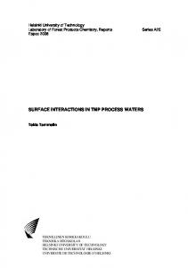
Figure 3.1. Possible sources of serpentine in Finland. Circles mark areas where the distance to a major stationary CO2 emitter is < 50 km (Teir et al., 2006a).
(Isohanni et al., 1985). A large part of the mineral deposit is barren in nickel. Low nickel-grade ore is stored as waste rock at the mining site for future use, while the processed ore is stored in tailing ponds (Table 3.2). The total nickel ore hoist has been about 14 Mt, which had an average Ni content of 0.60%
13
(Teir et al., 2006b). If the hoisted ore has an average MgO content of 34 wt-%, 5.3 Mt of CO2 could be stored using the presently hoisted ore alone. 3.1.3
Alkaline solid waste materials While most research into mineral CO2 sequestration focuses on the carbonation of
natural silicate minerals, there have also been considerable and successful efforts to carbonate solid alkaline waste materials. Many various types of solid alkaline waste materials are available in large amounts and are generally rich in calcium. Wastes that have been considered for carbonation include ash from coal-fired power plants (CaO content up to 65 wt-%), bottom ash (~20 wt-% CaO) and fly ash (~35 wt-% CaO) from municipal solid waste incinerators, de-inking ash from paper recycling (~35 wt-% CaO), steelmaking slag (~30-60 wt-% CaO and MgO), and waste cement (Fernández Bertos et al., 2004; Johnson, 2000; Huijgen et al., 2005; Iizuka et al., 2004; Yogo et al., 2004; Uibu et al., 2005). Most research seems to have concentrated on carbonation as a means for immobilising toxic elements and heavy metals, as well as improving the structural durability of wastes and by-products to render them better suited for landfill or construction purposes. However, carbonation has also been found to increase the leaching of certain elements, such as vanadium in steel slag (Huijgen and Comans, 2006). Finland has a large steel industry, which is very energy-intensive and has high CO2 emissions. The largest single source of anthropogenic CO2 emissions in Finland, accounting for 4.7 Mt of CO2/a (Ruukki, 2005), is the steel plant at Raahe. Carbonating the steelmaking slags, which are by-products of the steelmaking processes, could be an interesting option for reducing the CO2 emissions from the steel plant. 3.1.3.1
Iron and steel slag Iron and steel slags (in short: steelmaking slags) are non-metallic by-products of
many steelmaking operations and consist principally of calcium, magnesium, and aluminium silicates, as well as iron and manganese. The proportions vary with the conditions and the feedstock for the particular iron or steel production process where the slag is generated. Calcium compounds account for the largest constituents, with a CaO content of 40-52% (Stolaroff et al., 2005). Crude or pig iron is produced in a blast furnace, where lime or limestone is used to remove oxygen and other impurities from iron and adjust the viscosity of the smelts. Limestone decomposes at high temperatures (see Chapter 3.2.5, Equation 36) and combines with impurities, such as silicon dioxide (SiO2), to form a liquid calcium silicate melt called iron or blast furnace slag, which can be removed from the blast furnace separately from iron.
14
xCaO + ySiO2 → (CaO )x ⋅ (SiO 2 )y
(5)
After the blast furnace, the crude iron produced is transported to a steel converter, usually a basic oxygen furnace (BOF), where the residual carbon content of the iron is reduced from 4 wt-% to 0.5 wt-%. Steel furnaces, particularly electric arc furnaces (EAF), may also use scrap metals as feedstock instead of pig iron. Impurities and carbon are also removed in the steel furnace by slag formation similarly to that in a blast furnace. Stainless steel grades (> 10 wt% Cr) are usually produced in an induction or electric arc furnace, sometimes under vacuum. To refine stainless steel, a so-called argon-oxygen decarburisation (AOD) process is used. The physical attributes of the solidified slags depend mainly on the cooling technique used: air-cooled, granulated (water-cooled), and pelletised (or expanded) slags are the three main types. The cooling method also largely determines the uses for the slag. After cooling, the slag may be further processed (mainly by crushing) prior to being sold (USGS, 2003). Steel slags are highly variable with respect to their composition, even those from the same plant and furnace. Apart from the feedstock impurities, slags (especially steel converter slags) may also contain significant amounts of entrained free metal. The amount of slag produced is largely related to the overall chemistry of the raw materials (Ahmed, 1993). The chemical composition of the slag is also variable and depends on both the chemical composition of the feed and the type of furnace used. Slags are widely used for road construction purposes, as asphalt and cement aggregate. Slags have very low prices (e.g. blast furnace slag from Ruukki can be bought for 10 €/t, excluding shipping costs) in comparison to steel products and are usually considered to be unwanted by-products of the steel production process.
Table 3.3. Production of steel mills in Finland in 2004 (units: kt/a). Steel
CO2e
Ferrochrome
Steel mill
Company
production
emissions
Iron slag
Steel slag
slag
Raahea
Ruukki
2719
4740
571
302
-
Ovako
618
890
96
62
-
Tornio
Outokumpu
1200
670
-
47
309
Imatrad
Ovako
243
58
36f
b
Koverhar c
-
a
Data from Ruukki (2005).
b
Data supplied by Magnus Gottberg, Ovako.
c
Data from Outokumpu (2005).
d
Data supplied by Helena Kumpulainen, Ovako.
e
Finland’s total anthropogenic CO2 emissions in 2004 were 69 Mt (excluding land use, land use change, and
forestry: STAT, 2007). f
Number represents the total steelmaking slag production of the mill.
15
Table 3.4. Examples of average compositions of various slag products from steel producers in Finland (units: wt-%). CaO
SiO2
MgO
Al2O3
Cr
Fe
Ti
Mn
41
35
10
9.2
0.0
0.6
1.0
0.4
Steel converter slaga
46
13
2.1
1.7
0.2
18
0.5
2.5
b
40
26
11
5.8
5.2
1.1
2.3
1.8
56
30
8.3
1.2
0.3
0.6
0.4
0.3
39
36
17
3.5
1.0
0.3
1.1
0.2
1.4
28
23
28
8.5
4.6
no data
no data
Blast furnace slag
a
EAF slag
AOD process slag
b b
Chrome converter slag b
Ferrochrome slag a
Data from Rautaruukki steel plant at Raahe.
b
Data from Outokumpu steel plant at Tornio.
As mentioned above, the steel industry is very energy-intensive and has high CO2 emissions. It has been estimated that the world output in 2003 was 160-200 Mt of iron slag and 96-145 Mt of steel slag (USGS, 2003). In Finland, there are four steel plants in operation that produce a total of 1.4 Mt of slag per year (Table 3.3). Examples of the composition of the slag these plants produced in 2004 are listed in Table 3.4. The high carbonation conversion achieved with steel slag with relatively mild process conditions (see Chapter 3.2.4) shows that steelmaking slags are suitable materials for carbonation.
3.2 Carbonation processes The major challenge hindering the large-scale use of silicate minerals for CO2 sequestration is their slow conversion to carbonates. Therefore, most research in this field has focused on identifying faster reaction pathways, by characterisation of the mineral reactants and reaction products, as well as bench-scale experiments for determining reaction rates. Although the raw materials required are relatively cheap and the net carbonation reaction is exothermic, the process conditions (high pressures and temperatures) and additional chemicals for speeding up the carbonation reaction contribute to excessive process costs. However, several carbonation process routes that appear promising have been suggested. In the case of mineral-containing rocks, carbonation can be carried out either in situ, by injecting CO2 into silicate-rich geological formations or alkaline aquifers, or ex situ in a chemical processing plant after mining the silicates (IPCC, 2005). Since this thesis considers the use of both steelmaking slags and of minerals, as well as the end products, only ex situ processes are relevant for this research. These processes can be divided into two main routes: direct processes, where the carbonation of the mineral takes place in a single process step, and
16
indirect processes, where calcium or magnesium is first extracted from the mineral and subsequently carbonated. 3.2.1
Weathering of rocks The idea of CO2 disposal by carbonate formation comes from the natural silicate
weathering process, which binds about 100 Mt of carbon per year (Seifritz, 1990)6:
CaSiO 3 (s) + 2CO 2 (aq) + H 2 O(l) → Ca 2 + (aq) + 2HCO 3− (aq) + SiO 2 (s), ∆H = −63 kJ/mol CO 2
(6)
Rainfall is slightly acidic by nature, because atmospheric carbon dioxide dissolves in rainwater, producing weak carbonic acid. Calcium is therefore leached from calcium silicatecontaining rocks by rainwater containing dissolved CO2 (Brownlow, 1996). Magnesium silicates (olivine and serpentine) are similarly dissolved by rainwater:
Mg 2SiO 4 (s) + 4CO 2 (aq) + 2H 2 O(l) → 2Mg 2 + (aq) + 4HCO 3− (aq) + SiO 2 (s), ∆H = −280 kJ/mol CO 2 Mg 3Si 2 O 5 (OH) 4 (s) + 6CO 2 (aq) + H 2 O(l) → 3Mg 2 + (aq) + 6HCO 3− (aq) + 2SiO 2 (s),
∆H = −349 kJ/mol CO 2
(7)
(8)
Rainwater carries the leached calcium and magnesium to rivers and subsequently to the ocean, where calcium and magnesium precipitates and forms solid calcium and magnesium carbonates (M2+ represents either Ca2+ or Mg2+): M 2 + (aq) + CO 32 − (aq) → M 2 + CO 32- (s)
(9)
The precipitation and dissolution of carbonates controls the pH in the oceans naturally, according to the equilibrium involving CO2 and calcium carbonate (Brownlow, 1996):
CO 2 (g) ↔ CO 2 (aq)
(10)
H 2 O(l) + CO 2 (aq) ↔ H 2 CO 3 (aq) ↔ HCO 3− (aq) + H + (aq) ↔ CO 32− (aq) + 2H + (aq) 6
(11)
All enthalpy differences are calculated at 25 °C using Outokumpu HSC 5.1 with additional
thermodynamic data for MgCO3 from Robie et al. (1978) unless supplementary text specifies otherwise.
17
M 2+ CO 32- (s) + H 2 CO 3 (aq) ↔ M 2 + (aq) + 2HCO 3− (aq)
(12)
Increasing the CO2 abundance will increase the amount of H2CO3, which in turn results in more dissolved carbonate minerals. Reducing the CO2 abundance will result in the precipitation of solid carbonates. Using solubility constants and Henry’s law, the distribution of carbonate species can be presented as functions of pH (Figure 3.2).
100 CO32-
HCO3-
H2CO3(aq) 80
60
% 40
20
00 4
5
6
7
8
9
10
11
12
Figure 3.2 Distribution of carbonate species at equilibrium as functions of pH (calculated using Henry’s law) (Paper V).
The application of the weathering of rocks for CO2 sequestration was studied experimentally by Kojima et al. (1997). The aqueous carbonation of finely ground wollastonite (a representative diameter of 80 µm was reported) was tested in a continuously stirred tank reactor exposed to CO2 at 25 °C and atmospheric pressure for 0-600 h. It took 400 hours before the concentration equilibrium of the calcium in the solution was reached, which is far too slow for an industrial application. 3.2.2
Direct carbonation The routes via which the carbonation of the mineral takes place in a single process step
are usually referred to as direct carbonation. These processes can further be divided into gassolid processes and aqueous (three-phase) processes. 3.2.2.1
Direct gas-solid carbonation In a direct gas-solid (dry) carbonation process, the only reactants are CO2 and a
mineral. This approach, first presented and studied by Lackner et al. (1995), is to convert 18
silicate minerals directly to carbonates (according to the reactions presented in Equations 2-4) using gaseous or supercritical CO2. The advantages of the direct carbonate approach are its simplicity and the possibility of recovering heat at high temperatures. The high temperature heat that is generated could possibly be used for process requirements or even electricity generation (Zevenhoven and Kavaliauskaite, 2004). The reaction proceeds very slowly at room temperature, but the rate can be accelerated by increasing the temperature. However, above a certain temperature the reaction equilibrium shifts and favours free CO2 instead of carbonates. This temperature limit can be raised by increasing the CO2 pressure. The highest reported conversion by direct carbonation appears to be 25% of the stoichiometric maximum, which was achieved by exposing serpentine particles of 100 µm to a CO2 pressure of 340 bars and a temperature of 500 °C for 2 h (Lackner et al., 1997a). 3.2.2.2
Direct aqueous carbonation The most comprehensively studied carbonation process is the direct aqueous
carbonation of magnesium silicates (O’Connor et al., 2000; Gerdemann et al., 2007). In this process a slurry of water and pre-treated olivine (Equations 13 and 14) or serpentine (Equation 15) is reacted with pressurised carbon dioxide to produce magnesium carbonate. Although the conversion chemistry involves three steps, it takes place in a single reactor. Carbon dioxide is dissolved in water to form carbonic acid (H2CO3), which dissociates to hydrogen cations (H+) and bicarbonate anions (HCO3-) (Equations 10 and 11). The hydrogen cations reacts with the mineral, liberating magnesium cations (Mg2+), which react with the bicarbonate to form solid carbonate and silicic acid (which in turn becomes silica and water). According to O’Connor et al. (2005), the same process could be used for carbonating Ca- and Fe(II)-rich silicates as well (Equations 16 and 17).
2Mg 2SiO 4 (s) + CO 2 (g) + 2H 2 O(l) → Mg 3Si 2 O 5 (OH) 4 (s) + MgCO 3 (s), ∆H = −157 kJ/mol CO 2 Mg 2 SiO 4 (s) + 2CO 2 (g) + 2H 2 O(l) → 2MgCO 3 (s) + H 4 SiO 4 (aq), ∆H = −80 kJ/mol CO 2
Mg 3Si 2 O 5 (OH) 4 (s) + 3CO 2 (g) + 2H 2 O(l) → 3MgCO 3 (s) + 2H 4SiO 4 (aq), ∆H = −37 kJ/mol CO 2 Fe 2SiO 4 (s) + 2CO 2 (g) + 2H 2 O(l) → 2FeCO 3 (s) + H 4SiO 4 (aq), ∆H = −57 kJ/mol CO 2
CaSiO 3 (s) + CO 2 (g) + 2H 2 O(l) → CaCO 3 (s) + H 4SiO 4 (aq), ∆H = −75 kJ/mol CO 2
19
(13)
(14)
(15)
(16)
(17)
Preliminary tests conducted at ambient temperature and sub-critical CO2 pressures (below 74 bar) resulted in very slow carbonate formation. In later tests, using an aqueous solution of sodium bicarbonate (NaHCO3) and sodium chloride (NaCl) at elevated temperatures and pressures, several silicate minerals were successfully carbonated to a large extent in one hour (Table 3.5). The lowest costs reported from a case-specific feasibility study regarding storing CO2 using this method were 54 US$/tCO2 with olivine as feedstock, 64 US$/tCO2 with wollastonite as feedstock, and 78 US$/tCO2 using serpentine as feedstock (O’Connor et al., 2005; Gerdemann et al., 2007). The study included pre-treatment costs, but excluded CO2 separation and transport costs (see Table 1.1 for these). Huijgen et al. (2006) managed to carbonate wollastonite to a conversion of 70% in 15 min at 200 ºC, 20 bar CO2, using a particle size of 20
21
bar) that allow for reasonable carbonation reaction kinetics under conditions where magnesium carbonate is thermodynamically stable. Thermodynamic calculations indicated that the process could be operated at close to zero energy input. The process is currently being further investigated. 3.2.3.2
Production of hydroxides for carbonation using HCl Lackner et al. (1995; 1997b) and Butt et al. (1998) studied a carbonation process
consisting of several steps, where magnesium hydroxide is first produced from minerals using an acidic solution, and carbonated as a gas-solid reaction (Figure 3.3). The carbonation could alternatively also be performed at low pressures in an aqueous environment. First, the mineral containing rock is decomposed in hydrochloric acid (HCl) at ~100 ºC, forming magnesium chloride in the solution. The process steps using serpentine are given as examples:
Mg 3Si 2 O 5 (OH) 4 (s) + 6HCl(aq) → 3MgCl 2 (aq) + 2SiO 2 (s) + 5H 2 O(l),
(22)
∆H = −236 kJ/mol
The silica forms a gel that can be recovered by filtration. Any excess acid and water is boiled off at 150 ºC, where the formed solid magnesium chloride (MgCl2) decomposes and hydrochloric acid is regenerated:
MgCl 2 ⋅ 6H 2 O(s) → Mg(OH)Cl(s ) + HCl(g) + 5H 2 O(g)
(23)
∆H = 398 kJ/mol
HCl, H2O Mg(OH)Cl
Reformation Mineral
Dissolution
Filtration
Dehydration
Filtration Ca(OH)2 / Mg(OH)2 SiO2 H2O
Carbonation
CaCO3 / MgCO3
Figure 3.3. Indirect process for carbonating minerals using HCl.
22
CO2
Endothermic
Mg(OH)2
20 Mg3Si2O5(OH)4 0 -20 -40 -60
MgCO3
-80
Exothermic
Relative change in free energy (kJ/mol)
40
MgCl2·6H2O -100 State of Mg
Figure 3.4. Relative free energy changes at the main process stages of the indirect carbonation process using HCl (after Butt et al., 1998).
After solution in water, magnesium hydroxide chloride forms magnesium hydroxide and magnesium chloride: H 2O 2Mg(OH)Cl( s) ⎯⎯ ⎯→ Mg(OH) 2 (s) + MgCl 2 (aq)
∆H = −127 kJ/mol
(24)
The magnesium hydroxide is separated, while the magnesium chloride is recycled through the acid recovery step. The solid magnesium hydroxide is carbonated at high temperatures and pressures (Equation 18, Chapter 3.2.3.1). The drawback of the process is its high energy demand for the evaporation of the aqueous solution and the large variations in free energy resulting from the necessary formation of intermediate products (Figure 3.4). Newall et al. (2000) calculated the process costs to be 233 US$/t CO2 sequestered. Additionally, to provide for the energy requirements of the process four times more CO2 would be produced (because of fossil fuel combustion at the power plant) than is sequestered by the process (Newall et al., 2000). The same process route could also be used for carbonating calcium silicates (Lackner et al., 1995; Newall et al., 2000). In this route (Figure 3.3), calcium silicate is dissolved in hydrochloric acid at 80 °C and calcium chloride (CaCl2) is produced:
CaSiO 3 (s) + 2HCl(aq) → CaCl 2 (aq) + SiO 2 (s) + H 2 O(l), ∆H = −93 kJ/mol
23
(25)
Silica is filtered out, and calcium chloride reacts with magnesium hydroxide chloride, Mg(OH)Cl, to produce calcium hydroxide, Ca(OH)2:
CaCl 2 (aq) + 2Mg(OH)Cl(s) → Ca(OH)2 (s) + 2MgCl2 (aq), ∆H = −106 kJ/mol
(26)
The calcium hydroxide produced is separated, dissolved in water, and then reacted with CO2 to produce calcium carbonate. The Mg(OH)Cl is regenerated by dehydrating saturated MgCl2 at 150 °C. Major drawbacks reported were the energy demand for the acid recycling stage and a very large water demand to hydrate the Ca(OH)2 for the carbonation stage: 840 t H2O/t Ca(OH)2 In order to lower the energy requirements for dehydration, several possibilities for dissolving minerals using molten salt (MgCl2·nH2O) instead of HCl were investigated by Wendt et al. (1998a; 1998b) using thermodynamic calculations. The direct carbonation of serpentinite in a molten salt melt at 300 °C using 30 bar CO2 was considered to be the most suitable alternative. The process was calculated to have a CO2 sequestration cost of ~80 US$/tCO2, but because of unavoidable losses of MgCl2 in the process during the separation of the carbonates produced from the melt, there would be a significant demand for make-up MgCl2 (or HCl for MgCl2 production), which would probably render the process economically unviable (Newall et al., 2000). 3.2.3.3
Indirect carbonation of calcium silicate using acetic acid A similar process for the carbonation of calcium silicate was studied by Kakizawa et
al. (2001). The chemical reactions in the process occur in two steps (Figure 3.5). The first step is the extraction of calcium ions from calcium silicate (e.g. wollastonite) using acetic acid (CH3COOH):
CaSiO3 (s) + 2CH3COOH(aq)→ Ca2+ (aq)+ 2CH3COO− (aq)+ SiO2 (s) + H2O(l), ∆H = −105 kJ/mol
(27)
The solid SiO2 precipitates and is separated using a thickener. Gaseous CO2 is injected into the solution, which causes calcium carbonate to crystallise and deposit:
Ca 2 + (aq) + CO 2 (g) + H 2 O(l) + 2CH 3COO − (aq) → CaCO 3 (s) + 2CH 3COOH(aq), ∆H = +16 kJ/mol
24
(28)
According to Kakizawa et al., the Gibbs free energy change of each step is negative, which indicates that the reactions would proceed spontaneously. At 25 °C, the theoretical conversion that can be achieved is 40% at 1 bar and 75% at 30 bar. The acetic acid is recovered in this step and recycled for use in the extraction step.
CO2 30 bar
CaSiO3
Extraction reactor 80 °C, 1 bar
Carbonation reactor 60 °C, 30 bar
Thickener
100% efficiency
CaCO3 Filter
10% efficiency SiO2 CH3COOH
Figure 3.5. Indirect carbonation of calcium silicate using acetic acid.
Kakizawa et al. conducted extraction experiments with wollastonite (particle size 1 wt-% are shown.
Table 5.3. Minerals in calcium silicate-based materials identified by XRD analyses (Paper II). Material analysed
Highest peak (counts)
Phases identified
Wollastonite
2500
wollastonite CaSiO3, quartz SiO2
AOD process slag
1000
fluorite CaF2, periclase MgO, calcium silicate Ca2(SiO4)
Electric arc furnace slag
350
gehlenite
Ca2Al(AlSiO7),
merwinite
Ca3Mg(SiO4)2,
magnesiochromite (Mg, Fe)(Cr,Al)2O4 Steel converter slag
300
srebrodolskite Ca2Fe2O5, lime CaO, iron Fe, calcium silicate Ca2SiO4, calcium iron oxide Ca2Fe15.6 O25
Blast furnace slag
Mostly amorphous phases
5.3 Dissolution of steelmaking slags The extraction of calcium from various iron and steel slags in solutions of acetic acid was studied using batch experiments (Paper II). The experiment setup is displayed in Figure 5.3. Acetic acid solutions of various concentrations were heated to 30, 50, and 70 °C in a glass reactor of 250 ml, which was put in a temperature-controlled water bath. The reactor was equipped with a tap-water condenser so as to prevent losses from evaporation of the solvent. Nitrogen was continuously fed to the reactor (above the surface of the solution) at 1 l/min to prevent the CO2 in the air from interfering with the experiments. The solution was stirred using a magnetic stirrer at approximately 600-700 rpm. When the temperature of the 45
solution had stabilised after heating up to the desired temperature, 4.2 g of a calcium silicatebased material was added to the solution. The solution was stirred for 2 h and samples were extracted during the experiment. The samples were immediately filtered through syringe membrane filters with a pore size of 0.45 µm and analysed for Ca, Mg, Si, Al, and Fe using ICP-AES and Atomic Absorption Spectrophotometry (AAS). The accuracy of the ICP-AES and AAS analyses were estimated to be ± 2%.
Gas out Cooling water out Batch feed
Cooling water in
Gas in
T, pH, samples
Temperature bath
Magnetic stirrer
Figure 5.3. Experimental setup (Paper II).
To compare the potential for leaching calcium out from iron and steel slags, various slags were dissolved in aqueous solutions of acetic acid (33 vol-%12 acetic acid and 67 vol-% distilled water, initial pH of 1.5) at 50 °C. The results from the AAS and ICP-AES analyses (Figure 5.4) show that only 51% of the calcium fixed in wollastonite could be extracted during 2 h, which is similar to the results reported by Kakizawa et al. (2001) (48% extracted during 250 min: see Chapter 3.2.3.3.). We found that the extraction of calcium from steelmaking slags was much faster; almost all the calcium from steelmaking slags dissolved in 15 minutes. The extraction efficiencies were calculated by comparing the concentration of selected elements in the filtered solution samples with the concentrations of the elements in the raw materials (Table 5.2) and accounting for the loss of solution volume resulting from sample extraction. However, other elements dissolve as well (see Figure 5.5), as predicted by the thermodynamic equilibrium calculations. The calculated extraction efficiency of blast furnace slag (Figure 5.4-Figure 5.5) was found to exceed 100%. This indicates that the
12
1 litre acetic acid = 1.05 kg
46
concentration of calcium in the blast furnace slag sample analysed (Table 5.2) was slightly lower than in the samples used in the experiments, although they were taken from the same batch. 120%
Calcium extraction
100%
80%
60%
40%
Blast furnace slag (350-500 µm) Steel converter slag (350-500 µm) Electric arc furnace slag (125-350 µm)
20%
AOD process slag (< 125 µm) Wollastonite (< 250 µm) 0% 0:00
0:15
0:30
0:45
1:00
1:15
1:30
1:45
2:00
Time in solution (h:mm)
Figure 5.4. Extraction of calcium from various steelmaking slags and wollastonite (batch of 4.2 g added at 0:00) in 250 ml aqueous solutions of acetic acid (33 vol-% CH3COOH).
Elements extracted after 2 h (%)
0
Concentration of acetic acid (vol-%) 10 20 30
120% 100% Ca Si Mg Al Fe
80% 60% 40% 20% 0% 0
10
20
30
40
50
Moles of acetic acid in solution per moles of Ca in slag
Figure 5.5. Effect of concentration of acetic acid (0 – 33 vol-%) upon dissolution of blast furnace slag (batch of 4.2 g added at 0:00, 250 ml solution kept at 50 °C).
47
Experiments were carried out with dissolving blast furnace slag at 50 °C in aqueous acetic acid solutions of varying concentrations. The results of the AAS and ICP-AES analyses show that the acetic acid concentration of the solution (i.e. the initial pH) has a dramatic effect upon the extraction of calcium in the range 0-10 vol-% acetic acid (Figure 5.5). Almost all of the calcium in the batch of slag was extracted in a solution of 10 vol-% acetic acid, which corresponds to 15 mol CH3COOH per mol Ca (Figure 5.5). The effect of temperature upon the extraction efficiency was also investigated for blast furnace slag at 30 and 70 °C. The results of the AAS and ICP-AES analyses (Figure 5.6) showed that temperature has a significant effect upon the solubility of calcium (and other elements as well) from blast furnace slag. At 30 °C the extraction is significantly slower than at 50 °C, but on the other hand more calcium can be extracted than at 50 or 70 °C. This is probably due to the solubility of calcium, which decreases with increasing temperature. However, this can be compensated for by increasing the acetic acid concentration in the aqueous solution: almost identical extraction efficiencies for all temperatures were achieved using a solution concentration of 33 vol-% (Teir et al., 2005).
100%
Calcium extraction
80%
60%
30 C 50 C 70 C
40%
20%
0% 0:00
0:15
0:30
0:45 1:00 1:15 Time in solution (h:mm)
1:30
1:45
2:00
Figure 5.6. Extraction of calcium from blast furnace slag in aqueous solutions (250 ml) of acetic acid (4 vol-%) at 30 °C, 50 °C, and 70 °C (batch of 4.2 g added at 0:00).
To produce a solution suitable for the precipitation of CaCO3, i.e. with a high concentration of calcium but a low concentration of silica, 50 g of blast furnace slag was dissolved in a 300-ml aqueous solution of 33 vol-% CH3COOH at 70 °C for 2 hours, after which the solution was filtered using membranes with a pore size of 0.45 µm. The filtrate contained 17 g Ca/l (37% dissolved), and only 0.13 g Si/l (0.3% dissolved), showing that it is 48
possible to minimise the dissolved silica content by leaching slag at 70 °C and removing the silicon-rich gel that is formed by mechanical filtration. However, other separation measures are needed to remove aluminium, iron, magnesium, and other elements released from the solution of the dissolved slag.
5.4 Precipitation of carbonates Since blast furnace slag was found to be easy to dissolve and contain low amounts of iron (an unwanted element in PCC), blast furnace slag was selected for carbonation experiments. The experiments were performed using a similar reaction setup as in Figure 5.3. The possibility of producing precipitated carbonates from blast furnace slag was tested using two different approaches: 1) by injecting CO2 into filtered acidic solutions containing dissolved blast furnace slag, and 2) by first precipitating acetates by evaporation and then injecting CO2 into aqueous solutions of the slag-derived acetates. 5.4.1
Carbonation of dissolved blast furnace slag Solutions suitable for carbonation, i.e. with high concentrations of calcium and low
concentrations of silica, were prepared similarly to those in the extraction experiments: 25-50 g of blast furnace slag (0.5-1 mm) was dissolved in a glass reactor (250 or 500 ml) filled with an aqueous solution of acetic acid (20-33 vol-% acetic acid) at 70 ºC for 2 h under constant N2 gas flow (1 l/min) and stirring (600-1000 rpm), after which the solution was vacuum filtered using Supor membranes (0.45 µm). This produced solutions containing 11-19 g Ca/l, 2-4 g Mg/l, and 1 g Al/l. The solutions also contained small amounts of Fe and Si (0.1-0.3 g/l). The carbonation of 225 ml aqueous solutions of acetic acid and dissolved blast furnace slag was tested at 30, 50, and 70 °C. After heating up to the desired temperature under nitrogen flow (1 l/min), the nitrogen flow was switched to carbon dioxide gas flow (1 l/min). After four hours of continuous exposure to the carbon dioxide flow, the reactor was removed from the bath and the solution was filtered. The filtered solids were dried and analysed using XRD. Only 0.3-0.7 g of precipitate per litre of solution was formed in the experiments. No carbonate had been formed; the dried precipitates contained magnesium acetate hydrate and calcium acetate hydrate. Because of the low initial pH of the solution (pH 3), the precipitation of carbonates was apparently impossible (see Figure 3.2 and Chapter 5.1.3). In a conventional PCC production process (Chapter 3.2.5) the precipitation of calcium carbonate occurs in an alkaline environment. Additionally, Kodama et al. (2006) calculated that in order to precipitate calcium carbonate out of an aqueous solution a pH >5 is required. In order to raise the alkalinity of the solution, the precipitation experiments at 30, 50, and 70 °C were repeated with the addition of sodium hydroxide (aqueous solution of 50 wt-% NaOH) during carbonation. After the temperature of the prepared solution (100 ml) had 49
stabilised under nitrogen flow and the gas flow had been switched to carbon dioxide (1 l/min), the sodium hydroxide solution was added stepwise until the acidic solution became alkaline (pH 11.0-11.6). The change was also visibly noticeable, since the solution turned from clear to white. One hour after the final addition of sodium hydroxide, when the pH level had settled at pH 7, the resulting slurry was cooled to room temperature, rinsed with nitrogen gas, and filtered using syringe membrane filters with a pore size 0.45 µm. At all three temperatures, 16 ml 50 wt-% NaOH was required to make the solution alkaline, which corresponds to 10-11 g of NaOH per gram of calcium in solution. The XRD analyses of the filtered and dried precipitates showed that the precipitates contained calcium carbonate in the form of aragonite and calcite, as well as sodium acetate, calcium aluminium oxide, and carbonates containing both magnesium and calcium (Table 5.4). While calcite magnesium was the dominant form of carbonate at 30 °C, raising the temperature to 70 °C seemed to favour the formation of aragonite and calcite.
Table 5.4. Phases identified by XRD in filtered precipitates from carbonation experiments with dissolved blast furnace slag where sodium hydroxide was added. Temperature Phases identified (in descending apparent order of magnitude) (°C) 30
Calcite magnesium ((0.06Mg, 0.94Ca)(CO3)),Calcium aluminium oxide (Ca3(AlO3)2, Calcite (CaCO3), Sodium acetate (CH3COONa), Aragonite (CaCO3)
50
Calcite magnesium ((0.06Mg, 0.94Ca)(CO3)), Calcite (CaCO3), Sodium acetate (CH3COONa), Aragonite (CaCO3), Calcium aluminum oxide (Ca3(AlO3)2
70
Sodium acetate (CH3COONa), Calcite (CaCO3), Aragonite (CaCO3), Calcite magnesium ((0.06Mg, 0.94Ca)(CO3)), Calcium aluminium oxide (Ca3(AlO3)2
5.4.2
Carbonation of acetates derived from blast furnace slag Since large amounts of NaOH were required for precipitating calcium carbonate from
the solutions containing dissolved blast furnace slag, the possibility of raising the alkalinity (and recovering more acetic acid) by evaporation of the excess acetic acid was tested. Solutions were prepared similarly to those in the extraction experiments: 50 g of blast furnace slag ( 265 ºC, and that the decomposition of magnesium carbonate to CO2 and MgO should take place at temperatures > 406 ºC. Three runs from 25 to 900 ºC were performed in an N2 atmosphere, using heating rates of 2 ºC/min, 5 ºC/min (Figure 7.1), and 10 ºC/min, respectively. After an initial mass loss of 2-6 %-units during heating up from 25 to 170 ºC, the material decomposed mainly in two clearly endothermic steps: first, at 170-300 ºC a mass loss of an additional 12-17%-units occurred, after which 3538%-units were lost during heating up from 300 to 550 ºC. The total mass loss that occurred during heating up from 25 to 300 ºC (18-21 wt-%) is similar to the total molar weight of water that can be released by the dehydration and dehydroxylation of hydromagnesite (19 wt-%)17:
Mg5 (OH)2 (CO3 ) 4 ⋅ 4H 2 O(s) → 4MgCO3 (s) + Mg(OH)2 (s) + 4H 2 O(g), ∆H = 170 kJ/mol
Mg(OH) 2 (s) → MgO(s) + H 2 O(g),
∆H = 81 kJ/mol
(57) (58)
The net loss of mass during heating up from 300 to 550 ºC (44-51 wt-%) corresponds to the expected loss of mass caused by the release of CO2 (47 wt-%):
17
All reaction enthalpies have been calculated for 25 ºC. Reaction enthalpies were calculated using
Outokumpu HSC 5.1 software with additional data for MgCO3, MgO, and Mg(OH)2 from Robie et al. (1978).
79
MgO(s) + 4MgCO 3 (s) → 5MgO(s) + 4CO 2 (g),
∆H = 118 kJ/mol MgCO 3
(59)
The TGA analysis and thermodynamic calculations indicate that hydromagnesite should be a safe and stable CO2 storage medium up to 300 ºC. However, in order to verify these results, the experiments could be repeated using an FT-IR gas analyser to measure the CO2 content in the gas at the outlet of the TGA reactor.
Figure 7.1. Thermogravimetric analysis of precipitated hydromagnesite in N2 atmosphere (heating rate: 5 K/min). TG = mass change of the sample; DTG = rate of the mass change; DTA = local minima indicate endothermic reactions, while local maxima indicate exothermic reactions.
7.3 Discussion The results from the various analyses of the experiments performed indicate that a relevant dissolution of magnesium carbonates and calcium carbonates occurs only for strong acidic solutions. Concluding from the experimental results and literature data, magnesium carbonate should be a more stable option than calcium carbonate for storing CO2. At pH = 1, the release of gaseous CO2 was very low for calcium carbonate and even lower for magnesium carbonate. The higher carbonate content of leached carbonate minerals and the measured CO2 gas release imply that acid rain would not necessarily have a negative effect on
80
the amount of CO2 stored. When taking into account the relatively low acidity of rain water and the very low rates and amounts of CO2 gas emitted from nitric acid solution leaching of carbonates, the local environmental effects of CO2 emissions from a carbonate mineral storage site would probably be insignificant, even if the storage site were not protected from rainwater. The small amount of magnesium carbonates dissolved by rainwater would eventually be transported to the seas and oceans, as in natural weathering (see Chapter 3.2.1). However, experiments in batch reactors eventually reach a solubility equilibrium, which prevents further leaching of the carbonate. If the carbonate were continuously rinsed with an acidic solution it would eventually dissolve completely. A flow-through reactor would be a better choice for simulating the leaching effect of rainfall or a continuous flow of large volumes of acidic water. More research on this issue should therefore be conducted when mineral carbonation technology matures. The thermal stability study of hydromagnesite shows that it should be a safe and stable storage medium for CO2 up to 300 ºC. Since the solubility of hydromagnesite in water is lower than that of lansfordite (used in the tests presented in Chapter 7.1), hydromagnesite seems to be a suitable material for the long-term storage of CO2.
81
8 Conclusions The carbonation of magnesium and calcium silicates is an interesting alternative to geological storage methods, providing for permanent storage of carbon dioxide in the form of solid carbonates. Finland has large resources of potentially suitable magnesium silicates that could be used for several hundred years for the mitigation of CO2 emissions from industrial sources. Industrial residues and by-products, especially steelmaking slags, also appear suitable for carbonation. While the available slag resources are significantly lower than those of natural minerals, these materials are produced steadily and could help introduce carbonation technology, since slags are more reactive than natural minerals. The work reported in this thesis was concentrated on the design and evaluation of new multi-step, indirect carbonation processes for the fixation of CO2 by the production of carbonates from natural minerals and steelmaking slags. Since only scant experimental data related to indirect carbonation processes were found in the literature, the main part of the work was on the experimental determination of process parameters. Additionally, the stability of carbonates as media for the storage of CO2 was preliminarily assessed. From the work presented in this thesis, the following issues can be concluded: •
The additional value from producing pure calcium carbonates from steelmaking slag would make for a far more expensive carbonation process than the current market value of CO2 allows. o
The high price and limited resources of wollastonite mineral make it an unattractive material for carbonation
o
Steelmaking slag, which is steadily produced and cheap, could provide for local CO2 emission reductions by carbonation
•
Acidic solutions extract calcium or magnesium from minerals and steelmaking slag efficiently, but the acidity of the solutions prevents the precipitation of carbonate. o
Strong acids are required for extracting magnesium from serpentinite.
The dissolution (i.e. extraction of Mg) kinetics of serpentinite in HCl, HNO3 or H2SO4 at 30-70 ºC was found to be restricted by product layer diffusion.
o
Steelmaking slags dissolve more easily than wollastonite in aqueous solutions of acetic acid.
o
For maximum extraction or gel facilitation the solution temperature should be 70 ºC or possibly higher.
82
•
Evaporation recycles only part of the solvent, since part of the solvent is converted into a salt (e.g. magnesium and calcium acetate, nitrate, or chloride).
•
While iron oxides and amorphous silica can each be separated easily from serpentinite upon dissolution in acids, steelmaking slags contain many other compounds as well, which may require additional separation measures (depending on the materials used).
•
As CO2 dissolves in a neutral, aqueous magnesium/calcium salt solution, the solution turns acidic and prevents the precipitation of carbonate. Therefore, a base must be added to raise the pH of the solution and precipitate dissolved magnesium, calcium, and CO2 as carbonates. o
The temperature of the solution affects the morphology of the precipitated carbonates, but not the yield.
o
The optimal amount of NaOH for the precipitation of hydromagnesite was similar to the stoichiometric requirements for cation exchange with magnesium-bearing salt.
•
A new process concept, based on experimental results and procedures, was constructed and evaluated. The process concept allows for the production of relatively pure calcite (80-90%) from blast furnace slag and pure hydromagnesite (99%) from serpentinite. o
Preliminary process calculations indicated that a similar process (Kakizawa et al., 2001) could store more CO2 than is indirectly produced by the process. However, successful extraction of calcium ions was found to demand a surplus of acid, which effectively prevents the precipitation of carbonates from the solution. Therefore, a modification of the process approach is required.
o
Calculations concerning the suggested process concept showed that the process would produce 3-4 times more CO2 than is stored in the process as a result of the electricity requirements for the regeneration of spent chemicals.
•
Preliminary experiments with magnesium carbonate (as lansfordite) and calcium carbonate (as calcite) indicated that these should be safe alternatives for the storage of CO2, as regards their low solubility, even in lean acidic solutions. Calculations and TGA experiments indicated that the hydromagnesite produced should likewise provide safe and permanent and practically leakage-free storage of CO2
Experimental research has shown that CO2 can be bound into pure and stable carbonate products using silicate-based materials. While relatively pure carbonate products and byproducts, such as amorphous silica and iron oxides, can be produced using the processes presented here, the current obstacle to scaling up the suggested processes seems at this point
83
to be the regeneration of the additional chemicals spent in the process. The products and the by-products of the processes may have some commercial value, but the regeneration of NaOH and acid probably requires electrical power, which makes the process as such unfeasible as an overall storage method for CO2. However, the potential to simultaneously produce pure synthetic minerals and the possibility that a costly CO2 capture step could be omitted are significant benefits which warrant more research on the development of indirect, multi-step mineral CO2 sequestration processes.
8.1 Significance of this work In this work, the CO2 storage potential in Finland of wollastonite and steelmaking slag has been assessed for the first time. The findings show that the carbonation of Finnish wollastonite for CO2 storage would give very small emission reductions and that it is too expensive as a CO2 storage process. However, it was also found that by carbonating Finnish steelmaking slags almost one per cent of Finland’s annual anthropogenic CO2 emissions could be disposed of. In comparison to these results, Finnish serpentinites seem to have by far the largest potential for CO2 sequestration. Reliable experimental data are valuable for the further development of a functional mineral carbonation process. This work presents new experimental data with respect to the dissolution of natural minerals and steelmaking slags in various acids and bases. The results give an overview of the suitability of common solvents for the extraction of magnesium from serpentinites or serpentine. Apart from their application in mineral carbonation processes for the storage of CO2, the results can also be used in the mineral processing industry, where valuable metals are extracted from serpentinites. The fixation of CO2 by the precipitation of magnesium carbonates and calcium carbonates from solutions containing dissolved serpentinite or blast furnace slag has also been studied. Only very scant public research data were previously available on the precipitation of carbonates from magnesium and calcium actually extracted from silicate minerals or steelmaking slags. The results shed some more light on feasible precipitation parameters and process requirements. A new concept for producing relatively pure precipitated calcium and magnesium carbonates from calcium silicates and magnesium silicates was suggested. Although the process concept does not in its current form bring about a net reduction in CO2 emissions, it is one of the few indirect carbonation process concepts presented in the public literature that is primarily based on experimentally verified results. It also demonstrates that it is possible to produce a relatively pure calcite from blast furnace slag and a pure hydromagnesite from serpentinite.
84
Previous to this work, only scant experimental data had been presented on the stability of synthetic calcium carbonate and magnesium carbonate as media for storing CO2. Although the studies presented here are preliminary, the results indicate that carbonates are safe and stable CO2 storage materials, even when exposed to acid rain.
8.2 Recommendations for future work The current obstacle to the process concept under study seems to be the major requirements for make-up solvent and chemicals that can raise the pH of the solution, such as sodium hydroxide. Additionally, the additional separation requirement for unwanted elements (mainly metals) after dissolution is another problem, making the concept more difficult to apply to steelmaking slags. While serpentinite seems to require strong acids for extracting magnesium, steelmaking slag could possibly be extracted in solvents milder than acetic acid. However, if the primary goal is to bind very large volumes of CO2, then only natural magnesium silicate reserves provide sufficient storage capacity. The ideal solvent would be a solvent that extracts magnesium and/or calcium selectively from the silicate material and is alkaline after dissolution. The selectivity could nearly eliminate the need for additional separation methods and produce pure carbonate products. The alkalinity of a solution containing calcium and magnesium would favour the rapid precipitation of carbonates, and the solution could possibly be used as such for stripping flue gas of CO2. Future work should therefore aim in the first place to reduce the requirements for additional chemicals by focusing on solvent selection and the development of more reversible methods. Integration with other industrial processes could allow alkaline or acidic waste streams from these to be used in the carbonation process and should therefore also be investigated. These issues are currently being further studied at Helsinki University of Technology. Alternatively, a simpler process that compromises carbonate product quality and therefore would not require the use of expensive chemical additives and solvents could be a better alternative for storing CO2. An example could be the staged gas-solid serpentine carbonation processes that are being developed at Åbo Akademi University.
85
References AATOS, S., SORJONEN-WARD, P., KONTINEN, A., KUIVASAARI, T., 2006. Serpentiinin ja serpentiniitin hyötykäyttönäkymiä (Outlooks for utilisation of serpentine and serpentinite). Geological Survey of Finland (GSF), Report No. M10.1/2006/3, Kuopio, Finland.
ACID NEWS, 2007. June 2007, p.21. The Swedish NGO Secretariat on Acid Rain. Available from: http://www.acidrain.org/pages/publications/acidnews/2007/documents/AN2-07.pdf
[Accessed
26
November 2007].
AHMED, I., 1993. Use of Waste Materials in Highway Construction. William Andrew Publishing/Noyes.
APOSTOLIDIS, C.I., DISTIN, P.A., 1978. The kinetics of the sulphuric acid leaching of nickel and magnesium from reduction roasted serpentine. Hydrometallurgy, 3, 181–196.
BLENCOE, J.G., ANOVITZ, L.M., BEARD, J.S., PALMER, D.A., 2003. Carbonation of Serpentine for Long-Term CO2 Sequestration. In: FY 2003 ORNL Laboratory Directed Research and Development Annual Report, Oak Ridge National Laboratory.
BLENCOE, J.G., PALMER, D.A., ANOVITZ, L.M., BEARD, J.S., 2004. Carbonation of Metal Silicates for Long-Term CO2 Sequestration; Patent application WO 2004/094043. BROWNLOW, A.H., 1996. Geochemistry. 2nd Edition. U.S.A.: Prentice-Hall.
BUTT, D.P., LACKNER, K.S., WENDT, C.H., CONZONE, S.D., KUNG, H., LU, Y.-C., BREMSER, J.K., 1996. Kinetics of Thermal Dehydroxylation and Carbonation of Magnesium Hydroxide. Journal of the American Ceramic Society, 79(7), 1892–1898.
BUTT, D.P., LACKNER, K.S., WENDT, C.H., VAIDYA, R., PILED, L., PARK, Y., HOLESINGER, T., HARRADINE, D.M., NOMURA, K., 1998. The Kinetics of Binding Carbon Dioxide in Magnesium Carbonate.
In: Proceedings of the 23rd international technical conference on coal
utilization and fuel systems, Clearwater, FL (United States), 9-13 March 1998. CASEY, J., 1983. Pulp and Paper: Chemistry and Chemical Technology, 3rd ed., vol. 4. WileyInterscience.
CHEN, Y., BRANTLEY, S.L., 2000. Dissolution of forsteritic olivine at 658C and 2-pH-5. Chem. Geol. 165, 267–281.
86
CIULLO, P.A. (ed.), 1996. Industrial Minerals and Their Uses - A Handbook and Formulary. William Andrew Publishing/Noyes.
COX, K.G., BELL, J.D., PANKHURST, R.J., 1979. The interpretation of igneous rocks. U.K.: Chapman & Hall.
DAHLBERG, K., 2004. Phone conversation, Nordkalk Finland, 10 August 2004.
EMEP, 2004. EMEP measurement data online [online]. Convention on Long-Range Transboundary Air Pollution, Co-operative programme for monitoring and evaluation of the long-range transmissions of air pollutants in Europe. Web page: http://www.nilu.no/projects/ccc/onlinedata/; read 13 October 2004.
ESKOLA, P., HACKMAN, V., LAITAKARI, A., WILKMAN, W., 1929. Kalkstenen i Finland (Limestone in Finland). Geotekniska meddelanden N:o 21, Geologiska kommisionen i Finland.
FERNÁNDEZ BERTOS, M., SIMONS, S.J.R., HILLS, C.D., CAREY, P.J., 2004. A review of accelerated carbonation technology in the treatment of cement-based materials and sequestration of CO2. Journal of Hazardous Materials, B112, 193–205. FOUDA, M.F.R., AMIN, R. E.-S., ABD-ELZAHER, M.M., 1996a. Extraction of Magnesia from Egyptian Serpentine Ore via Reaction with Different Acids. I. Reaction with Sulfuric Acid. Bulletin of the Chemical Society of Japan, 69(7), 1907–1912.
FOUDA, M.F.R., AMIN, R. E.-S., ABD-ELZAHER, M.M., 1996b. Extraction of Magnesia from Egyptian Serpentine Ore via Reaction with Different Acids. II. Reaction with Nitric and Acetic Acids. Bulletin of the Chemical Society of Japan, 69(7), 1913–1916.
FUJII, M., YAMASAKI, A., KAKIZAWA., M., YANAGISAWA, Y., 2001. Reduction of CO2 emission by treatment of waste concrete via an artificial weathering process. American Chemical Society, Fuel Chemistry Division Preprints, 46(1), 75–77.
GERDEMANN, S.J., O’CONNOR, W.K., DAHLIN, D.C., PENNER, L.R., RUSH, H., 2007. Ex Situ Aqueous Mineral Carbonation. Environ. Sci. Technol. 41, 2587–2593.
GOFF, F., LACKNER, K.S., 1998. Carbon Dioxide Sequestering Using Ultramafic Rocks. Environmental Geosciences, 5 (3), 89–101.
GSF, 2004. Kiviopas (Rock reference guide), Geological Survey of Finland. Available from: http://www.gsf.fi/aineistot/kiviopas [Accessed 17 April 2004].
87
HASE, A., KOPPINEN, S., RIISTAMA,, K., VUORI, M., 1998. Suomen kemianteollisuus. Tampere, Finland: Tammer-Paino Oy.
HUIJGEN, W.J.J., COMANS, R.N.J, 2003. Carbon dioxide sequestration by mineral carbonation. Energy
research
Centre
of
the
Netherlands
(ECN),
Report
number
ECN-C--03-016. Available from: http://www.ecn.nl [Accessed 27.7.2005].
HUIJGEN, W.J.J., COMANS, R.N.J, 2005. Carbon dioxide sequestration by mineral carbonation – Literature Review Update 2003-2004. Energy Research Centre of the Netherlands (ECN), Report number ECN-C--05-022. Available from: http://www.ecn.nl [Accessed 3.11.2005].
HUIJGEN, W.J.J., COMANS, R.N.J, 2006. Carbonation of Steel Slag for CO2 Sequestration: Leaching of Products and Reaction Mechanisms. Environmental Science & Technology, 40, 2790–2796.
HUIJGEN, W.J.J., WITKAMP, G.-J., COMANS, R.N.J, 2005. Mineral CO2 sequestration by steel slag carbonation. Environmental Science & Technology, 39, 9676–9682.
HUIJGEN, W.J.J., WITKAMP, G.-J., COMANS, R.N.J, 2006. Mechanisms of aqueous wollastonite carbonation as a possible CO2 sequestration process. Chemical Engineering Science, 61, 4242–4251. HÄNCHEN, M., PRIGIOBBE, V., STORTI, G., SEWARD, T.M., MAZZOTTI, M., 2006. Dissolution kinetics of fosteritic olivine at 90–150 ºC including effects of the presence of CO2. Geochimica et Cosmochimica Acta, 70, 4403–4416.
IEA, 1993. Greenhouse Gas Emissions from Power Stations. IEA Greenhouse Gas R&D Programme, ISBN 1-898373-10-8.
IEA, 2007. GHG Greenhouse Issues Vol. 87 (September 2007). IEA Greenhouse Gas R&D Programme (ISSN 0967 2710).
IIZUKA, A., FUJII, M., YAMASAKI, A., YANAGISAWA, Y., 2004. Development of a new CO2 sequestration process utilizing the carbonation of waste cement. Industrial & Engineering Chemistry Research, 43, 7880–7887.
IMPPOLA, O., 2000. Precipitated calcium carbonate-PCC. In: Lehtinen, E. (Ed.), Pigment Coating and Surface Sizing of Paper, Jyväskylä, Finland: Gummerus Printing.
IPCC, 2001a. Climate Change 2001: Mitigation. Contribution of Working Group III to the Third Assessment Report of the Intergovernmental Panel on Climate Change (IPCC).
88
IPCC, 2001b. Climate Change 2001: The Scientific Basis. Contribution of Working Group I to the Third Assessment Report of the Intergovernmental Panel on Climate Change (IPCC). Houghton, J.T., Ding, Y., Griggs, D.J., Noguer, M., van der Linden, P.J., Xiaosu, D. (Eds.). UK: Cambridge University Press.
IPCC, 2005. IPCC Special Report on Carbon Dioxide Capture and Storage. Prepared by Working Group III of the of the Intergovernmental Panel on Climate Change. Metz, B., Davidson, O. de Coninck, H.C., Loos, M., Meyer, L.A. (Eds.). Cambridge University Press, Cambridge.
IPCC, 2007. Climate Change 2007: The Physical Science Basis. Contribution of Working Group I to the Fourth Assessment Report of the Intergovernmental Panel on Climate Change. Solomon, S., D. Qin, M. Manning, Z. Chen, M. Marquis, K.B. Averyt, M. Tignor and H.L. Miller (Eds.). Cambridge University Press, Cambridge, United Kingdom and New York, NY, USA.
ISOHANNI, M., OHENOJA, V., PAPUNEN, H., 1985. Geology and nickel-copper ores of the Nivala area. Geological Survey of Finland, Bulletin, 333, 211–228.
JOHNSON, D.C., 2000. Accelerated carbonation of waste calcium silicate materials. SCI Lecture Paper Series 108, 1–10. Society of Chemical Industry.
JONCKBLOEDT, R.C.L., 1998. Olivine dissolution in sulphuric acid at elevated temperatures – implications for the olivine process, an alternative waste acid neutralizing process. Journal of Geochemical Exploration, 62, 337–346.
KAKIZAWA, M., YAMASAKI, A., YANAGISAWA, Y., 2001. A new CO2 disposal process via artificial weathering of calcium silicate accelerated by acetic acid. Energy, 26, 341–354.
KATSUYAMA, Y., YAMASAKI, A., IIZUKA, A., FUJII, M., KUMAGAI, K., YANAGISAWA, Y., 2005. Development of a Process for Producing High-Purity Calcium Carbonate (CaCO3) from Waste Cement Using Pressurized CO2. Environmental Progress, 24(2), 162–170. KODAMA, S., NISHIMOTO, T., YOGO, K., YAMADA, K., 2006. Design and evaluation of a new CO2 fixation process. Poster presented at the 8th International Conference on Greenhouse Gas Control Technologies (GHGT-8), 19-22 June 2006, Trondheim, Norway.
KOJIMA, T., NAGAMINE, A., UENO, N., UEMIYA, S., 1997. Absorption and fixation of carbon dioxide by rock weathering. Energy Conversion and Management, 38, 461–466.
KOLJONEN, T., SIIKAVIRTA, H., ZEVENHOVEN, R., SAVOLAINEN, I., 2004. CO2 capture, storage and reuse potential in Finland. Energy, 29, 1521–1527.
89
KOPPINEN, S., RIISTAMA, K., VUORI, M., 2003. Suomen Kemianteollisuus. Tampere, Finland: Tammer-Paino Oy.
MINISTRY OF THE ENVIRONMENT, 2001. 2001 – Finland's third national communication under the United Nations Framework Convention on Climate Change. UNFCCC Call number FIN/COM/3 B. Kuusisto, E., Hämekoski, K (Eds.). Helsinki, Finland: Ministry of the Environment. Available from: http://unfccc.int/resource/docs/natc/finnc3.pdf [Accessed 1 November 2005].
MINISTRY OF TRADE AND INDUSTRY, 2005. Lähiajan energia- ja ilmastopolitiikan linjauksia kansallinen strategia Kioton pöytäkirjan toimeenpanemiseksi. National Climate and Energy Strategy. Available from: http://www.ktm.fi/energia-_ja_ilmastostrategia [Accessed 19.2.2007].
NORDKALK, 2007. Environmental Report 2006. Available from: http://www.nordkalk.com/ [Accessed 16.10.2007].
LACKNER, K.S., WENDT, C.H., BUTT, D.P., JOYCE, E.L., SHARP, D.H., 1995. Carbon Dioxide Disposal in Carbonate Minerals. Energy, 20 (11), 1153–1170.
LACKNER, K.S., BUTT, D.P., WENDT, C.H., 1997a. Magnesite disposal of carbon dioxide. In: Proceedings of the 22nd International Technical Conference on Coal Utilization and Fuel System, Clearwater Florida (U.S.), 16-19 March 1997, 419–430.
LACKNER, K.S., BUTT, D.P., WENDT, C.H., 1997b. Progress on binding CO2 in mineral substrates. Energy Conversion and Management, 38, 259–264.
LACKNER, K.S., 2002. Carbonate Chemistry for Sequestering Fossil Carbon. Annu. Rev. Energy Environ., 27, 193–232.
LACKNER, K.S., 2003. A guide to CO2 sequestration. Science, 300, 1677–1678. LEVENSPIEL, O., 1972. Chemical Reaction Engineering, second ed. John Wiley & Sons, New York.
LUCE, R.W., BARTLETT, R.W., PARKS, G.A., 1972. Dissolution kinetics of magnesium silicates. Geochimica et Cosmochimica Acta, 36, 35–50.
MATHUR, K., 2001. High speed manufacturing process for precipitated calcium carbonate employing sequential pressure carbonation. Patent application WO 01/07365.
90
MCKELVY, M.J., CHIZMESHYA, A.V.G., DIEFENBACHER, J., BÉARAT, H., WOLF, G., 2004. Exploration of the Role of Heat Activation in Enhancing Serpentine Carbon Sequestration Reactions. Environmental Science & Technology, 38, 6897–6903.
MAROTO-VALER, M.M., FAUTH, D.J., KUCHTA, M.E., ZHANG, Y., ANDRÉSEN, J.M., 2005a. Activation of magnesium rich minerals as carbonation feedstock materials for CO2 sequestration. Fuel Processing Technology, 86, 1627–1645.
MAROTO-VALER, M.M., ZHANG, Y., KUCHTA, M.E., ANDRÉSEN, J.M., FAUTH, D.J., 2005b. Process for sequestering carbon dioxide and sulphur dioxide. US Patent US2005/0002847.
MCGRAIL, B.P., SCHAEF, H.T., HO, A.M., CHIEN, Y.-J., DOOLEY, J.J., DAVIDSON, C.L., 2006. Potential for carbon dioxide sequestration in flood basalts. Journal of Geophysical Research, 111, B12201, 1–13.
NEWALL, P.S., CLARKE, S.J., HAYWOOD, H.M., SCHOLES, H., CLARKE, N.R., KING, P.A., BARLEY, R.W., 2000. CO2 storage as carbonate minerals. Report number PH3/17. Cheltenham (U.K.): International Energy Agency (IEA) Greenhouse Gas R&D Programme.
O'CONNOR, W.K., DAHLIN, D.C., NILSEN, D.N., WALTERS, R.P., TURNER, P.C., 2000. Carbon dioxide sequestration by direct mineral carbonation with carbonic acid. In: Proceedings of the 25th international technical conference on coal utilization and fuel systems, 6-9 March 2000, Clearwater, Florida, U.S.A.
O’CONNOR, W.K., DAHLIN, RUSH, G.E., GERDEMANN, S.J., PENNER, L.R., NILSEN, D.N., 2005. Aqueous Mineral Carbonation, Final Report, DOE/ARC-TR-04-002, 15 March 2005.
OUTOKUMPU,
2005.
Outokumpu
and
the
environment
2004.
Available
from:
http://www.outokumpu.com/24526.epibrw [Accessed 27 September 2005].
OUTOKUMPU MINING, 1998. Hitura. Leaflet published and distributed by Outokumpu Mining oy, Hitura mine. Eds: Isomäki O.-P., Pulkkinen, K., Koskinen, J.
PARK, A.-H.A., FAN, L.-S., 2004. CO2 mineral sequestration: physically activated dissolution of serpentine and pH swing process. Chemical Engineering Science, 59, 5241–5247.
PARK, A.-H.A., JADHAV, R., FAN, L.-S., 2003. CO2 Mineral Sequestration: Chemically Enhanced Aqueous Carbonation of Serpentine. Canadian Journal of Chemical Engineering, 81, 885–890.
91
ROBIE, R.A., HEMINGWAY, B.S., FISHER, J.R., 1978. Thermodynamic Properties of Minerals and Related Substances at 298.15 K and 1 Bar (105 Pascals) Pressure and at Higher Temperatures. U.S. Geological Survey Bulletin 1452. Washington, U.S.: United States Government Printing Office. Reprinted with correction 1979.
ROSKILL, 2007. Summary of the report The Economics of Precipitated Calcium Carbonate. Roskill Information Services. Available from: http://www.roskill.com/report.html?id=36 [Accessed 23 October 2007].
RUUKKI,
2005.
Raahe
Steel
Works
Environmental
Statement
2004.
Available
from:
http://www.ruukki.com/ [Accessed 30 September 2005].
SEIFRITZ, W., 1990. CO2 disposal by means of silicates. Nature, 345, 486. STAT, 2003. Energy in Finland 2002. Kerava, Finland: Statistics Finland, ISBN 952–467–256–1.
STAT, 2007. Greenhouse gas emissions in Finland 1990-2005. National Inventory Report to the UNFCCC. Statistics Finland, April 15th 2007. Available from: http://www.stat.fi/greenhousegases [Accessed 6 October 2007].
STOLAROFF, J.K., LOWRY, G.V., KEITH, D.W., 2005. Using CaO- and MgO-rich industrial waste streams for carbon sequestration. Energy Conversion and Management, 46, 687–699.
SÖDERHOLM, K., 2005. Tilastotietoja vuoriteollisuudesta 2004 (Statistics from the mining industry 2004). Finnish Association of Mining and Metallurgical Engineers. Materia 2/2005, 45.
TEIR, S., RAISKI, T., KAVALIAUSKAITE, I., DENAFAS, G., ZEVENHOVEN, R., 2004. Mineral Carbonation and the Finnish Pulp and Paper Industry. In: The Proceedings of the 29th International Technical Conference on Coal Utilization & Fuel Systems, 18-22 April 2004, Clearwater, Florida, USA.
TEIR, S., ELONEVA, S., ZEVENHOVEN, R., 2005. Co-utilization of CO2 and calcium silicate-rich slags for precipitated calcium carbonate production (part I). In: Proceedings of ECOS 2005, Trondheim, Norway, 20-22 June 2005, 749–756.
TEIR, S., AATOS, S., ISOMÄKI, O-P., KONTINEN, A., ZEVENHOVEN, R., 2006a. Silikaattimineraalien karbonoiminen hiilidioksidin loppusijoitusmenetelmänä Suomen oloissa (Silicate mineral carbonation as a possible sequestration method of carbon dioxide in Finland). Finnish Association of Mining and Metallurgical Engineers. Materia, 1/2006, 40–46.
92
TEIR, S., ELONEVA, S., AATOS, S., ISOMÄKI O-P., FOGELHOLM, C-J., ZEVENHOVEN, R., 2006b. Carbonation of Finnish magnesium silicates for CO2 sequestration. In: Proceedings of the Fifth Annual Conference on Carbon Capture and Sequestration, 8-11 May 2006, Alexandria, Virginia, U.S.A. (CD-ROM).
UIBU, M., MUULMANN, M.-L., KUUSIK, R., 2005. CO2 wet mineralization by oil shale ash and model compounds. Poster presented at the 4th Minisymposium on Carbon Dioxide Capture and Storage, 8-9 September 2005, Espoo, Finland. Available from: http://eny.tkk.fi/minisymposium [Accessed 4.11.2005].
USGS, 2003. Minerals yearbook, vol. I – Metals and minerals. Reston (VA, U.S.): United States Geological
Survey.
Available
from:
http://minerals.usgs.gov/minerals/pubs/commodity/myb/
[Accessed 29 September 2005].
WENDT, C.H., BUTT, D.P., LACKNER, K.S., ZIOCK, H.-J., 1998a. Thermodynamic calculations for acid decomposition of serpentine and olivine in MgCl2 melts I, II, III. LA-UR-98-4528, LA-UR-984529, LA-UR-98-4529, LA-UR-98-5633, Los Alamos National Laboratory, Los Alamos, U.S.A.
WENDT, C.H., BUTT, D.P., LACKNER, K.S., ZIOCK, H.-J., 1998b. Thermodynamic considerations of using chlorides to accelerate the carbonate formation from magnesium silicates. LA-UR-98-3612, Los Alamos National Laboratory, Los Alamos, U.S.A.
YOGO, K., TENG, Y., YASHIMA, T., YAMADA, K., 2004. Development of a new CO2 fixation/utilization process (1): recovery of calcium from steelmaking slag and chemical fixation of carbon dioxide by carbonation reaction. Poster presented at the 7th International Conference on Greenhouse Gas Control Technologies (GHGT) in Vancouver, BC, Canada, 5-9 September 2004.
ZEVENHOVEN, R., KAVALIAUSKAITE, I., 2004. Mineral carbonation for long-term CO2 storage: an exergy analysis. International Journal of Thermodynamics, 7(1), 23–31.
ZEVENHOVEN, R., TEIR, S., 2004. Long term storage of CO2 as magnesium carbonate in Finland. Poster presented at the Third Annual Conference on Carbon Capture and Sequestration, Alexandria (VA), May 3-6, 2004.
ZEVENHOVEN, R., ELONEVA, S., TEIR, S., 2006a. A study on MgO-based mineral carbonation kinetics using pressurised thermo-gravimetric analysis. Poster presented at the 8th International Conference on Greenhouse Gas Control Technologies (GHGT-8), 19-22 June 2006, Trondheim, Norway.
93
ZEVENHOVEN, R., TEIR, S., ELONEVA, S., 2006b. Chemical fixation of CO2 in carbonates: Routes to valuable products and long-term storage. Catalysis Today, 115, 73–79.
ZEVENHOVEN, R., TEIR, S., ELONEVA, S., 2006c. Heat optimisation of a staged gas-solid mineral carbonation process for long-term CO2 storage. In: Proceedings of ECOS 2006, Crete, Greece, 12-14 July 2006.
94
ISBN 978-951-22-9352-0 ISBN 978-951-22-9353-7 (PDF) ISSN 1795-2239 ISSN 1795-4584 (PDF)