Nov 18, 2002 - D. Daytonb, M. DeMellox, W.S. Dengb, A.A. Derevschikovv, .... The Solenoidal Tracker at RHIC (STAR) is one of two large detector systems con ...
Feb 21, 2007 - Email: [email protected] construction of ... the bulk material will be type inverted. ... readout time, the pixel address is sent in a digi-.
Jun 24, 2014 - (PSD) as hadronic calorimeter. In muon ... out of 8 tracking layers populated with double-sided micro-strip silicon sensors placed from 30.
Overview of laser communication technology at NASA Goddard Space Flight Center. William L. Hayden, Michael A. Krainak, Donald M. Cornwell, Jr. Anthony W.
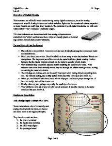
Digital Electronics. Dr. Pogo. Lab #1. Page 1 of 8. Overview of Digital Circuits.
This semester, we will build some circuits having mostly digital components, but a
...
and JSP, advanced servlets and JSP, Struts, JSF/MyFaces, Ajax,. GWT ..... Here
are some typical questions he has received (most of them repeatedly).
This report is an overview of biogas technologies with the aim of introducing them
in a ... which is using biogas technology as part of manure management.
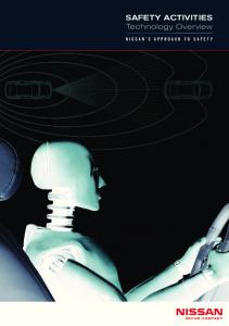
Battery Test. 1.5V. 10mV. ±(1.0% reading + 2 digits). NOTE: Accuracy specifications consist of two elements: ⢠(% rea
Since our target is to design a blowing detector that detects any blowing sound .... input signal. 2) Divide PSD data into frequency bands with average energy.
photography and airborne imaging. However, the ..... using in-house software (DiMerge) to produce a colour image that is 10500 Ã 7200 pixels. (= 75Ã6 ...
Homer Antoniadis | OLED Product Development| page:1. Overview of OLED Display Technology. Homer Antoniadis, Ph.D. Product Development Group ...
Homer Antoniadis | OLED Product Development| page:1 Overview of OLED Display Technology Homer Antoniadis, Ph.D. Product Development Group Manager
Grow dealership communities with a valuable piece of marketing ... sale. Our digital communication strategy has a proven
2 citrix.com. Citrix XenMobile Overview | White Paper. Mobility is a top priority for
organizations. Why? Because more employees than ever before are.
2008 Storage Networking Industry Association. ... Reliable Service Practically no ... Network. Layer. Link. Layer. Physi
This can be done using the front panel, webpages, .... has a free download of a demonstration program (with fully commen
SM10000, this revolutionary system is built around a parallel array of independent ultra ... and TIO enable SeaMicro to
WAP Push ushers in a new generation of application capabilities, allowing
application ..... 9. All intellectual property rights in this work belong to Openwave
Systems Inc. ... The PPG uses the user's current active data or an analysis of the
scoring to auto scoring of sleep and ... scoring rules and features with auto-staging ... Training videos which review the important instructions provided in.
Figure 2 Structure of normal skin and schematic illustration of light remittance. R. G. B. Red. Brown. X. Figure 1 Graphic illustration of the RBX Color Space ...
Real World Safety: Nissan's concept of analyzing the causes of actual accidents
to develop and adopt effective ..... name) launched in 2002, Nissan introduced a
more advanced ... Facility diagram ... and then switches connection to enable
dire
Stress is defined as a physical, chemical, or emotional factor that causes physical or mental tension that can alter an
RT Application Information Packet. This seven page document provides details on how to apply to the Radiologic Technolog
Nov 1, 2009 ... Impact of ICT on Attainment, Motivation and Learning (Pittard et al., 2003). This
was the ...... www.elearningeuropa.info/extras/pdf/ict_impact.pdf.
to acquire the x-ray projection image. CR Reader to extract the electronic latent
image. Digital electronics to convert the signals to digital form. Display / Archive.
Overview of Digital Detector Technology J. Anthony Seibert, Ph.D. Department of Radiology University of California, Davis
Disclosure • Member (uncompensated) – BarcoBarco-Voxar Medical Advisory Board – ALARA (CR manufacturer) Advisory Board
Learning Objectives • Describe digital versus screenscreen-film acquisition • Introduce digital detector technologies • Compare cassette and cassettecassette-less operation in terms of resolution, efficiency, noise • Describe new acquisition & processing techniques • Discuss PACS/RIS interfaces and features