Department of Chemical Engineering, McMaster University, Hamilton ON L8S
4L7, Canada ...... j. l. white: 'Principles of polymer engineering rheology'; 1990,.
Overview
Polymer processing J. Vlachopoulos and D. Strutt After a brief introduction to the various types of polymers in use and the size and impact of the polymer processing industry, this overview focuses on the most important processes for thermoplastic materials, namely extrusion and injection moulding. Single and twin screw extruders are used for melting and pumping of polymers and for die extrusion for the production of lm, sheet, pipe, tubing, pro les and bres. Injection moulding is the process used for the production of numerous parts, small and large, by injecting a molten polymer into mould cavities. Various problems associated with these processes are discussed. Other processes described include: calendering, compression moulding, rotational moulding, powder injection moulding and thixomoulding. The overview concludes with a brief discussion of current trends and future challenges faced by the polymer industry. MST/5866 Dr Vlachopoulos (
[email protected]) is at the Centre for Advanced Polymer Processing and Design (CAPPA-D), Department of Chemical Engineering, McMaster University, Hamilton ON L8S 4L7, Canada and Dr Strutt is with Polydynamics, Inc., 1685 Main St. W., Suite 305, Hamilton, ON L8S 1G5, Canada. Manuscript received 8 November 2002; accepted 10 January 2003. # 2003 IoM Communications Ltd. Published by Maney for the Institute of Materials, Minerals and Mining.
Introduction Mankind has used natural polymeric materials such as wood, leather and wool since the beginning of history, but synthetic polymers became possible only after the development of rubber technology in the 1800s. The rst synthetic polymer material, celluloid, was invented by John Wesley Hyatt in 1869, from cellulose nitrate and camphor. A major breakthrough in synthetic polymers was the invention of Bakelite by Leo Hendrik Baekeland in 1907. Hermann Staudinger’s work in the 1920s clearly demonstrated the macromolecular nature of long chains of repeating units.1 The word ‘polymer’ comes from Greek, and it means ‘many parts’. The rapid growth of the polymer industry started shortly before the Second World War, with the development of acrylic polymers, polystyrene, nylon, polyurethanes and the subsequent introduction of polyethylene, polyethylene terephthalate, polypropylene and other polymers in the 1940s and 1950s. While only about 1 million tons were produced in 1945, the production of plastics in volume surpassed that of steel in 1981, and the gap has been continuously growing ever since. Pure polymers are seldom processed on their own. They are compounded with other materials, typically by mechanical blending or melt state mixing to produce pellets, powders or akes to be used in subsequent processing operations.2 Such compoundedproducts are referred to as ‘plastics’, which means ‘pliables’ in Greek. The compounds may involve llers (to reduce cost), reinforcements, other polymers, colourants, ame retardants, stabilisers (to prevent deterioration from light, heat or other environmental factors) and various processing aids. Synthetic polymers can be classi ed in two categories. Thermoplastics (by far the largest volume) can be melted by heating, solidi ed by cooling and remelted repeatedly. Major types are polyethylene (PE), polypropylene (PP), polystyrene (PS), polyvinyl chloride (PVC), polycarbonate (PC), polymethyl methacrylate (PMMA), polyethylene terephthalate (PET) and polyamide (PA, nylon). Thermosets are hardened by the application of heat and pressure, owing to crosslinking, i.e. the creation of permanent threedimensional networks. They cannot be softened by heating for reprocessing. Bakelite, epoxies and most polyurethanes are thermosets. DOI 10.1179/026708303225004738
The present overview is exclusively devoted to the processing of thermoplastics. Commercial thermoplastics are classi ed according to their performance as ‘commodity’ (low performance, such as PE, PP, PS and PVC), ‘Engineering’ (such as PC, nylon and PET) or ‘advanced’ (highest performance, such as liquid crystal polymers (LCPs), polyphenylene sulphide (PPS) and polyetheretherketone (PEEK)). The anticipated explosive growth in engineering and advanced polymers did not materialise. The use of plastics has been continuously growing throughout the past three decades, but mainly in the commodity category. Currently, commodity polymers amount to ~88% of the volume produced,3 engineering plastics ~12% and advanced less than 1%. Although the prices of advanced polymers per kilogram are much higher than those for commodity polymers, their global value to the economy is still very small. Commodity plastics have low strengths and stiffnesses when compared with metals or ceramics, and they tend to exhibit creep under an applied force. They also have temperature limitations in their use as solids (most melt in the range 100 – 250°C). The tensile moduli of commodity plastics are ~1 GPa (compared with 210 GPa for steel). Signi cant improvement can be achieved by alignment of the polymer chains. Actually, the carbon – carbon bonds are very strong, and single lament polyethylenes have been produced with modulus values exceeding that of steel. High orientation can be achieved by special processing techniques, for example extrusion and subsequent drawing at low temperatures. At low temperatures the polymer chains have limited mobility, and the orientation remains after stretching. Recent discoveries and developments of single site, metallocene based catalysts have resulted in new grades of commodity polymers having controlled molecular architecture with improved properties. The world production of polymers increased3 from 27 million tons in 1975 to ~200 million tons per year in 2000 and is still growing. According to a recent report,4 shipments of plastics products in the USA in 2000 amounted to $330 billion, and upstream supplying industries had sales of $90 billion, bringing the annual total to $420 billion. Total employment was estimated to be 2.4 million – about 2% of the US workforce. The growth of the polymer industry is a result of the unique combination of properties of plastic products, which include easy shaping and fabrication, low densities, resistance to corrosion, electrical and
Materials Science and Technology
September 2003 Vol. 19 1161
1162 Vlachopoulos and Strutt
Polymer processing
melt ow index (MFI, also called melt ow rate or MFR). This is an inverse measure of viscosity based on a rather crude test involving the extrusion of a polymer through a die of standard dimensions under the action of a prescribed weight.8 The MFI is the number of grams of polymer collected from the test apparatus in 10 min. Low MFI values mean high viscosity and high molecular weight, and high MFI values indicate the opposite. The following is the usual MFI range for some processes: extrusion 0.01 – 10, injection moulding 1 – 100, blow moulding 0.01 – 1, rotational moulding 1.5 – 20.
Screw extrusion
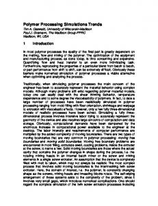
a schematic diagram 9; b screw channel geometry8
1 Single screw plasticating extruder
thermal insulation, and often favourable rigidity and toughness per unit weight.2 Thermoplastics are usually processed in the molten state. Molten polymers have very high viscosity values and exhibit shear thinning behaviour. As the rate of shearing increases, the viscosity decreases, owing to alignments and disentanglements of the long molecular chains. The viscosity also decreases with increasing temperature. In addition to the viscous behaviour, molten polymers exhibit elasticity. Elasticity is responsible for a number of unusual rheological phenomena.1 ,5 – 7 These include stress relaxation and normal stress differences. Slow stress relaxation is responsible for frozen in stresses in injection moulded and extruded products. The normal stress differences are responsible for some ow instabilities during processing and also extrudate swelling, i.e. the signi cant increase in cross-sectional area when a molten material is extruded out of a die. The most important polymer processing operations are extrusion and injection moulding. Extrusion is material intensive and injection moulding is labour intensive. Both these processes involve the following sequence of steps: (a) heating and melting the polymer, (b) pumping the polymer to the shaping unit, (c) forming the melt into the required shape and dimensions and (d) cooling and solidi cation. Other processing methods include calendering, blow moulding, thermoforming, compression moulding and rotational moulding. There are more than 30 000 grades of polymers processed by these methods. The suitability of a material for a particular process is usually decided on the basis of the
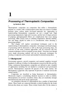
2 Melting in screw channel10
Materials Science and Technology
September 2003
Vol. 19
Most polymeric materials are extruded at least twice in their lifetime, rst through a pelletising die after the reactor and then for nal shaping.8 In simplest terms, screw extruders are polymer pumps with the capacity to melt the material which they are fed. Screw extruders comprise one or two Archimedean screws rotating in a heated barrel. The single screw extruder (SSE) is the workhorse of the plastics industry. Figure 1a shows a schematic diagram of an SSE,9 and Fig. 1b shows the geometry dimensions of a screw channel.8 Polymer resins in the form of pellets, powders or akes ow from a hopper to the gap between a rotating screw and a heated barrel. The depth of the conveying channel in the screw is contoured from large to small in the ow direction, to account for the density change from the particulate solid feed to the molten polymer extrudate, and for pressure development. The SSEs normally have diameters between 25 and 250 mm, and length/diameter ratios between 20 and 36. Usual rotation speeds range from 20 to 150 rev min2 1 . A 60 mm diameter machine may deliver up to 200 kg h2 1 , while a 150 mm diameter machine can exceed 1000 kg h2 1 . In the rst, or solids conveying, zone of the extruder, the solid polymer particles are compacted together in the screw channel by the rotating action of the screw to form a solid bed of material. At the start of the next extruder section, the plastication (melting) zone, barrel heaters cause a thin lm of molten polymer to form in the gap between the solid bed and the barrel wall. The melt lm is subjected to intense shearing in the thin gap, and because of the extremely high viscosities of molten polymers, high rates of viscous dissipation result. The generated heat melts the solid bed within a short distance of the start of melting. Figure 2 illustrates this process.1 0 In the last zone of the extruder, the metering section, the polymer melt ow is stabilised in the shallow screw channels, and nally the material passes out through the die at the end of the machine. Pressure buildup owing to frictional forces in the solids conveying section of the screw has been modelled by Darnell and Mol1 1 ,1 2 (along with some more recent research1 3 ) on the basis of force and torque balances, which result in an exponential expression. For forward motion of the solid bed, the friction coef cient must be larger on the barrel than on the screw. Screws have polished surfaces. The barrel surfaces are sometimes intentionally roughened (as in grooved barrels). Industrial experience shows that for good function of single screw extruders, the throughput should not be more . . . than 1.5mD or less than 0.75mD , where mD is the drag ow
Vlachopoulos and Strutt
Polymer processing 1163
capacity of the metering section, given by8 m _ D ~rm QD 1 ~ rm p2 D2 Hm N sin w cos w 2
:
:
:
:
:
:
: (1)
where QD is the volumetric ow rate, rm is the melt density, D is the screw outer diameter, Hm is the channel depth in the metering section, N is the screw rotation rate and w is the screw channel helix angle (frequently w~17.66°). The power provided by the rotating action of the screw goes to heating the polymer from room temperature to the extrusion temperature, melting the polymer and pumping it through the die.8 The barrel heaters usually provide less than 25% of the power required to raise the temperature and melt the polymer Po~rm QCp (Tout {Tin )zrm QHf zDPQ
:
:
:
: (2)
where Po is the power, Cp is heat capacity, T is the temperature, Q is the volume rate of ow, DP is the pressure change and Hf is the heat of fusion (zero for amorphous polymers such as PS and PMMA and up to 300 kJ kg2 1 for some high density PE grades). Extruders have poor pumping ef ciency, with the pumping term DPQ accounting usually for 10% of the total motor power supplied by the rotating screw. With the help of equation (2), it is easy to calculate that for extrusion of 400 kg h2 1 , a motor of ~120 kW would be required. In contrast with metals, energy costs for polymer processing are relatively low. The rule of thumb is that the plastics manufacturing cost is roughly equal to the raw materials cost. Power requirements contribute ~5% to the manufacturing cost of extrusion. To improve the mixing capabilities of single screw extruders, various types of mixing devices have been developed. Most prominent among these is the Maddock (or Union Carbide) mixer, in both straight and spiral variations. These devices are normally located at the downstream end of a screw, and improve melt quality by reducing temperature non-homogeneities in the polymer stream and increasing the dispersion and distribution of additives. Used increasingly in the extrusion industry are barrier screws and grooved barrels. Barrier screws have a secondary screw ight in the melting section of the screw, which serves to segregate the solid bed from the molten polymer. By independently controlling the dimensions of the solids and melt channels, the melting process can be accelerated and made more stable, thereby increasing the extruder output and melt quality. Grooved barrel extruders feature axial grooves or slots in the part of the barrel immediately following the feed throat. The grooved barrel can signi cantly enhance feeding of resin pellets and akes, and thereby sharply increase the output of the extruder above the drag ow output of equation (1). Twin screw extruders (TSEs) are extruders with two screws of the same diameter, which turn side by side within the extruder barrel at the same speed. In recent years, twin screw extruders have come into increasingly wider use in applications such as mixing, blending, compounding of thermoplastic polymers with additives, devolatilisation and reactive extrusion. The TSEs offer greater control over residence time distribution (RTD) and mixing than that of single screw extruders, and have superior heat and mass transfer capabilities. The disadvantage of TSEs compared with SSEs is their signi cantly higher capital cost. There are three major classes of twin screw extruders: corotating intermeshing, counter rotating intermeshing and counter rotating non-intermeshing. Figure 3 shows the three TSE classes.1 4 The screws are made up of conveying, kneading block and mixing sections. The screw design is frequently modular, which allows for a nearly unlimited
a corotating fully intermeshing; b counter rotating intermeshing; c counter rotating non-intermeshing
3
Twin screw con gurations14
number of possible screw con gurations. Kneading blocks comprise several discs staggered at an angle to one another, the motion of which causes intense shearing and has a chopping effect on the material stream. Most of the dispersive mixing (melt homogenisation and solids breakup) and melting that occurs within the extruder takes place in kneading blocks. Corotating intermeshing twin screw extruders are the most common type of TSE. These machines have the feature that their screws are self-cleaning, owing to their special design. This leads to narrower RTDs in these extruders than in SSEs, making them particularly attractive for use with thermal and shear sensitive materials, as there are no dead spots in which material can collect and degrade. Large twin screw extruders can rotate at more than 1200 rev min2 1 RPM with outputs of more than 10 tons/h.
Die extrusion Once a polymer has been melted, mixed and pressurised in an extruder, it is pumped through an extrusion die for Materials Science and Technology
September 2003
Vol. 19
1164 Vlachopoulos and Strutt
Polymer processing
5 Cast lm process: CR chill roll8
simplest being the power law model for the shear viscosity5 ) g~m_cn{1 : : : : : : : : : : : : : (4) txy ~g_c . where g is the viscosity, tx y is the shear stress, c is the shear rate and m and n are model parameters (m decreases exponentially with increasing temperature). The model predicts shear thinning of the uid, with exponent n values ranging from 0.2 to 0.8 for most polymers. To represent the dual viscous and elastic behaviour of polymer melts, the Maxwell viscoelastic model has been used1 7 l_tzt~m_c
4 Blown lm process18
continuous forming (after cooling and solidi cation) into a nal product. The most common die types are at, annular and pro le. Products made by extrusion include pipe, tubing, coating of wire, plastic bottles, plastic lms and sheets, plastic bags, coating for paper and foil, bres, laments, yarns, tapes and a wide array of pro les (e.g. window frames and sealing systems).8 Polymer extrusion through dies has certain similarities to the hot extrusion of metals.1 5 However, there are also signi cant differences. In metal extrusion the material is pushed forward by a ram, while in polymer extrusion the material is continuously supplied by a rotating screw. In hot metal extrusion the temperatures range from 340°C for magnesium to 1325°C for steel, and the corresponding pressures range from 35 to over 700 MPa.1 5 In polymer extrusion the temperatures seldom exceed 350°C, and pressures usually do not go much above 50 MPa at the screw tip. Solid phase extrusion of polymers has been developed for the production of certain high strength products.1 6 At low temperatures, the molecular orientation imparted by the forcing of the material through the shaping die remains in the extrudate. Solid state polymer extrusion has certain similarities to the cold extrusion of metals. Polymer melts in extrusion dies undergo creeping ow (characterised by very low Reynolds numbers, typically less than 102 4 ), owing to their extremely large viscosities. While the viscosity of molten metals is the same order of magnitude as that of water, commercial polymers in the molten state exhibit viscosities usually more than 106 times larger. The simpli ed form of the Navier – Stokes momentum conservation equation used in modelling these ows re ects the balance of viscous stress and pressure forces as follows5 {=Pz= t~0
:
:
:
:
:
:
:
:
:
:
:
: (3)
where P is the pressure and t is the stress tensor. A large number of constitutive relationships have been formulated to relate the stress and strain rate elds in polymer ows, the Materials Science and Technology
September 2003
Vol. 19
:
:
:
:
:
:
:
:
:
:
:
:
: (5)
where l is a relaxation time constant and m is the viscosity. To use this equation for ow problems, it must be expressed in a tensorially invariant frame of reference. Although numerous viscoelastic constitutive equations have been developed,1 7 they have had little impact on polymer process technology. Equipment design and process analysis of industrial installations is virtually always based on the solution of purely viscous shear thinning models. Blown lm extrusion is the most important process for the production of thin plastic lms from polyethylenes. The molten polymer is extruded through an annular die (normally of spiral mandrel construction) to form a thin walled tube which is simultaneously axially drawn and radially expanded. In most cases the blown lm bubble is formed vertically upwards. The maximum bubble diameter is usually 1.2 – 4 times larger than the die diameter. The hot melt is cooled by annular streams of high speed air from external air rings, and occasionally also from internal air distributors. The solidi ed lm passes through a frame which pinches the top of the bubble and is taken up by rollers. Coextruded lms with 3 – 8 layers (sometimes up to 11) are also produced by this process, for use in food packaging.8 Figure 4 shows a schematic diagram of the blown lm process.1 8 Cast lm and sheet extrusion involves extruding a polymer through a at die with a wide opening (up to 10 m), onto a chilled steel roller or rollers which quench and solidify the molten material. Film is generally de ned as a product thinner than 0.25 mm, while sheet is thicker than this. The cast lm process is used for very tight tolerances of thin lm, or for low viscosity resins. Most at dies are of T slot or coathanger designs, which contain a manifold to spread the owing polymer across the width of the die, followed downstream by alternating narrow and open slits to create the desired ow distribution and pressure drop. Most cast lm lines manufactured today are coextrusion lines, combining layers from as many as seven extruders into the product through multimanifold dies, or single manifold dies with the aid of feedblocks. Figure 5 shows a schematic diagram of the cast lm process.8
Vlachopoulos and Strutt
7 6 Wire coating die21
In lm extrusion, the shear rates at the die lips are usually ~103 s2 1 . When the wall shear stress exceeds a certain value (usually 0.14 MPa in research papers, higher in industry with the help of additives), the extrudate surface loses its gloss owing to the sharkskin melt fracture phenomenon.1 9 Sharkskin can be described as a sequence of ridges visible to the naked eye, perpendicular to the ow direction. Pipe and tubing extrusion involves pumping a molten polymer through an annular die, following which the extruded product, while being pulled, passes through a vacuum sizer where it attains its nal dimensions. This is followed by spray or immersion cooling and cutting to xed lengths. Pipe of diameter up to 2 m or greater is made by this process, and tubing with diameters from 10 mm down to below 1 mm. The annular dies are normally of spider or spiral mandrel design.8 ,2 0 In wire and cable coating processes, individual wires or wire assemblies are pulled at very high speed through a crosshead die, at right angles to the extruder axis. In high pressure extrusion, the polymer melt meets the wire or cable before the die exit, for example insulating of individual wires. In low pressure extrusion, the melt meets the cable after the die exit, for example jacketing of assemblies of insulated cables.1 4 Very high shear rates are frequently encountered in this process (up to 106 s2 1 ) and low viscosity resins are used. Figure 6 shows a wire coating die.2 1 Pro le extrusion is a manufacturing process used for products of constant cross-section. These can range from simple shapes to very complex pro les with multiple chambers and ngers. Examples range from picture frame mouldings, to automotive trim, to edging for tabletops, to window lineals. The extruded materials are classi ed (roughly) as rigid or exible. The typical pro le extrusion line consists of an extruder pumping a polymer through a pro le die, followed by a sizing tank or calibrator, additional cooling troughs, a puller and a cutoff device. The design of pro le dies requires considerable experience and patience.8 Output limitations in pro le extrusion are encountered owing to either sharkskin (for thin products produced from high viscosity polymers) or the ability to cool thick walled products. Polymer pipe and pro le extrusion is similar to the hot extrusion of metals for the production of continuous hollow shapes of barlike objects. However, the mathematical modelling of these processes for metals is based mainly on elastic – plastic ow hypotheses.2 2 In melt spinning, the molten polymer ows through numerous capillaries in a spinneret (up to 1000). The polymer is delivered under pressure by a gear pump for accurate metering, after passing through a lter which follows the extruder. On exiting the capillaries, the laments are attenuated to the desired diameter.2 3 ,2 4 For the production of very thin bres, the melt blowing process2 5 is used. In this process the bres are attenuated by the drag force exerted by a high velocity air jet.
Polymer processing 1165
Calendering rolls producing plastic sheet26
Calendering The calendering of thermoplastics is an operation used for the production of continuous sheet or lm of uniform thickness, by squeezing the molten material between a pair of heated driven rolls.2 6 Figure 7 illustrates the calendering process. The molten material is fed to the calender rolls from a Banbury mixer and two roll mill system, or from a large extruder. The major plastic material to be calendered is PVC. Products range from wall covering and upholstery fabrics to reservoir linings and agricultural mulching materials. Owing to the large separating forces developed in the calender gap, the rolls tend to bend. This may result in undesirable thickness variations in the nished product. Compensations for roll de ections are provided by crowned rolls having a larger diameter in the middle than at the ends or by roll bending or roll skewing.2 7 Calender installations require large initial capital investment. Film and sheet extrusion are competitive processes because the capital investment for an extruder is only a fraction of the cost of a calender. However, the high quality and volume capabilities of calendering lines make them far superior for many products. Calendering in principle is similar to the hot rolling of steel into sheets. It is interesting to note that strip casting of semisolid alloys can be modeled with the help of the hydrodynamic lubrication approximation for a power law viscosity model, as in plastics calendering.2 8 The process of calendering is also used extensively in the paper industry.
Injection moulding Injection moulding is a two step cyclical process: (a) melt generation by a rotating screw, and (b) lling of the mould with molten polymer by the forward ramming of the screw (called a reciprocating screw), followed by a very short packing stage necessary to pack more polymer in the mould to offset the shrinkage after cooling and solidi cation. The material is held in the mould under high pressure until it has solidi ed suf ciently to allow ejection. Polymer injection molding has certain similarities to the die casting process of metals,1 5 in which molten metal is forced under high pressure into a steel mould or die. The metal, as the polymer, is pressed into all the crevices of the mould and the pressure is held while the metal freezes. In polymer injection moulding, the melt path into the mould starts with a sprue, and splits off into individual runners each feeding one of the multiplicity of mould cavities through a gate. Figure 8 shows schematically how these mould components are connected. Moulds can contain over 100 cavities, each producing a part per injection cycle. Cycle times range from a few seconds to over a minute. Numerous products ranging from boat hulls, lawn chairs and appliance Materials Science and Technology
September 2003
Vol. 19
1166 Vlachopoulos and Strutt
Polymer processing
9 Fountain ow streamlines and uid element deformation illustration29
8 Injection mould components: IM injection moulded
housings to radio knobs and bottle caps are injection moulded. Very high shear rates arise in injection moulding operations (usually up to 104 s2 1 ) and, to limit temperature increases from viscous heating and also to facilitate easy lling, low viscosity thermoplastic polymer grades are used. Injection moulding machines are rated by the size of their clamping systems, which are hydraulic, electrical or mechanical toggle systems used to hold the mould closed with suf cient force to resist the injection pressure. Machines available usually range from 5 tons for a shot of ~10 g to 5000 tons for shots of more than 50 kg (shot is the total amount of material pumped into the mould in a cycle, including that in the sprue, runners and cavities). Some bigger machines have also been built for the production of very large moulded products. Micromoulding, in which the shot size is below 1 g, is recently nding increased use in biomedical and nanotechnological applications. Mould cavity lling is characterised by the fountain effect, in which elements of the molten polymeric uid undergo complex shear and stretching motions as they catch up the free ow front and then move outwards to the cold walls. This phenomenon can impart considerable orientation to the resulting injection moulded part. While molecular orientation is used in extrusion to improve the mechanical properties, in injection moulding orientation is generally a nuisance.2 The orientation is further exacerbated during the packing stage. The consequent frozen in stresses can cause parts to become distorted, especially at elevated temperatures. Figure 9 shows streamlines and uid element deformation in fountain ow.2 9 Simulation of cavity lling is generally carried out on the basis of the Hele – Shaw ow approximation,3 0 ,3 1 which applies to viscous ow between two closely spaced plates. With this approximation, the two components of the equation of conservation of momentum are reduced into a single partial differential equation with pressure P as the unknown ³ ´ ³ ´ ç ç P ç ç P S z S ~0 : : : : : : : (6) ç x ç x ç y ç y „b where S~ 0 z2 =g dz, and b is the gap between the plates and g is the viscosity, which is a function of local shear rate. Simulation software is used extensively in the design of injection moulds, because of the ability of the Hele – Shaw ow approximation to describe reasonably well the mould lling process. More recently, however, three-dimensional models of ow simulation have come into use. Economics also provide an incentive for the use of software, as moulds can be extremely expensive to make, so minimising trial and error procedures on the factory oor is desirable. The Materials Science and Technology
September 2003
Vol. 19
software is used to design the part cavities, to balance runners, to visualise the lling process, and to predict orientation, shrinkage, warpage and weld lines in the product.3 2 ,3 3 Among the challenging problems faced in computer simulation is the prediction of shrinkage and warpage. Shrinkage is the difference in dimensions between the mould and the cooled moulded part. The main cause is the density increase which occurs as the melt freezes. Crystalline polymers such as polyamide (PA, nylon), high density PE, PET and PP give the worst problems,2 with shrinkages of 1 – 4%. Amorphous polymers such as PS, PMMA and PC have fewer problems, shrinking only 0.3 – 0.7%. Warpage is caused by the density changes mentioned above, and orientation imparted to the part during cavity lling and packing, decidedly in a non-uniform manner. Gas assist injection moulding involves the injection of nitrogen with the plastic, which creates a hollow void in the moulded part.3 4 This allows large parts to be moulded with lower clamp tonnage and signi cant material savings. This innovative process started in the 1980s and its use is rapidly growing. The process of reaction injection moulding (RIM) involves the injection of low viscosity liquids, which become reactive when mixed and polymerise within the mould.3 5 The advantage of this process is that the pressures are low owing to the low viscosities. A disadvantage is the requirement to handle highly toxic substances. Although initial projections called for signi cant growth in RIM, this did not materialise. In fact, some manufacturers of automotive parts by RIM have switched to conventional injection moulding.
Blow moulding Blow moulding is the process by which articles are formed by in ation of a molten resin to ll a mould cavity having the desired shape and dimensions. Bottles for soft drinks and other liquids are blow moulded. The two most important process variants are extrusion blow moulding and injection blow moulding.3 6 In extrusion blow moulding, an extruder pumps the melt through an annular die to form a molten tube or parison with well de ned and controlled dimensions. The parison is clamped between the two mould halves and is in ated by internal air pressure to take the shape of the mould cavity, which is usually cooled. Finally, the formed article solidi es as a result of cooling and the mould is opened to eject the article without damage. Depending on the thermal stability of the material, the extrusion process can be continuous or intermittent. Intermittent systems can use reciprocating screws which operate as rams, in the same manner as in injection moulding. Injection blow moulding is a two stage process. In the rst stage, the plastic is injected into a cavity where the preform is moulded. The preform is then transferred to the blow mould for in ation. Injection blow moulding
Vlachopoulos and Strutt
Polymer processing 1167
a before application of vacuum; b after application of vacuum
10
Thermoforming by application of vacuum40
offers the advantages of accurate dimensional control, elimination of scrap and the moulding in of threads before blowing. Extrusion blow moulding is preferred for containers with high length/diameter ratios and for products with handles.3 7 Polyethylene terephthalate or PET is the polymer most widely used in injection blow moulding, for carbonated drinks and water bottles. Stretch blow moulding is used to produce PET bottles of enhanced physical properties. In this process, stretching induces the formation of small lamellar crystals. These crystals result in more transparent and tougher products than those produced without stretch blowing, which have spherulitic crystals.
Compression moulding Compression moulding is the oldest technique for the production of polymer products,3 0 and is mainly used for thermosets. In this process the compound is pressed in the mould by the heated platens of a hydraulic press. This process is to some extent analogous to sheet metal stamping. Injection moulding of polymers has replaced compression moulding for some polymers, because of the advantages in materials handling and automation. However, compression moulding has an advantage in the processing of reinforced polymers.3 8 Owing to modest levels of deformation and stress involved in compression moulding, the reinforcing bres are not damaged. Very high bre concentrations and longer bres can be included in compression moulded products.
Thermoforming Thermoforming techniques involve the softening of thermoplastic sheets by heat, followed by forming by the application of vacuum, pressure, or a moving plug.3 9 The sheet may be stretched over a male mould (positive forming) or into a female mould (negative forming). On contact with the mould, heat is lost and the material regains stiffness as it cools. Geometries of thermoformed products are usually simple (boxes, food trays, various containers, refrigerator liners, computer cases). Thermoforming competes with blow moulding and injection moulding. The main advantages of this process are the relatively low cost of thermoforming machines and the very low cost of the moulds, and the ease of forming large area, thin section parts. Disadvantages are the limited product shapes possible, dif culties in obtaining the required thickness distribution, dif culty in controlling molecular orientation and limitations in service
temperature which may induce strain recovery or shrinkage. Thermoforming of thermoplastics has certain similarities to sheet metal forming.4 0 However, the strain rates involved in polymer sheet forming are much larger than for metals. Figure 10 shows a vacuum thermoforming process.
Rotational moulding In rotational moulding, a charge of plastic powder is placed in one half of a metal mould. The mould halves are then clamped together and heated while the mould rotates biaxially. The powder particles melt and coalesce to form a homogeneous layer on the surface of the mould. The mould is then cooled and the polymer layer densi es and solidi es.4 1,42 Rotational moulding competes with blow moulding, thermoformingand injection moulding for the production of hollow parts. The main advantages of this process are the simplicity of the moulds and the low capital investment requirement. Cycle times are large, ~15 – 30 min. Rotational moulding is mainly used for large tanks (up to 85 m3 reported), toys and hollow parts that require frequent design modi cations. The process of coalescence and subsequent densi cation4 3 ,4 4 is usually referred to as sintering by rotational moulding practitioners. In powder metallurgy, however, the term sintering usually refers to compaction of powders below their melting point.
Powder injection moulding and thixomoulding Powder injection moulding (PIM) and thixomoulding are two processes that use traditional polymer processing principles for the production of metal parts. In PIM, ne powders are blended into a ‘binder’ to hold the particles together, and are mixed with additives to form the ‘feedstock’. The feedstock is then used in suitably modi ed, but otherwise conventional, polymer injection moulding machines for injection into moulds. After debinding and heating, the metal welds together by a sintering process to form strong metal or ceramic parts. Various types of ferrous alloys and oxide ceramics are suited to this process.4 5 In thixomoulding, metal alloy granules are fed from a hopper into the gap between a barrel and a rotating screw, and are heated by shearing to form a semisolid slurry. The material is then injected into a heated mould. By cooling, the material is solidi ed, and then it is removed from the mould and trimmed. Magnesium, aluminium and zinc are suited to thixomoulding. Currently, magnesium is mostly used in this process.4 6 Materials Science and Technology
September 2003
Vol. 19
1168 Vlachopoulos and Strutt
Polymer processing
Current trends and future challenges The polymer industry experienced exponential growth during the latter half of the 20th century. There are about 50 resin producers around the world (the properties of many material grades are available from a single database4 7 ), the well known big chemical companies contributing most of the production volume of 200 million tons per year. The processing industry, on the other hand, is fragmented to tens of thousands of small and medium sized enterprises around the world. For example, Germany has 2500 plastics processing companies. Most of the manufacturers of extruders, injection moulding machines, and other types of equipment are also small or medium sized enterprises having fewer than 500 employees. The growth of the plastics industry is likely to continue, especially in developing countries. Plastics consumption is likely to increase as more people around the world try to satisfy their needs in transportation, food packaging, housing and electrical appliances. However, this industry is considered to have reached a stage of maturity. Research and development efforts by the major resin producers have been severely curtailed in recent years. The plastics processors and original equipment manufacturers are not big enough to sustain major R&D programmes that could lead to ‘quantum jumps’ in technology. At a recent workshop of university and industry experts,4 8 it was concluded that future efforts should go beyond machinery design and process analysis and optimisation. The focus should be on predicting and improving the product properties of polymer based products. The term ‘macromolecular engineering’ was introduced as being more descriptive of future developments in the transformation of monomers into long chain molecules and their subsequent shaping or moulding into numerous useful products. The prediction of end use properties of polymeric products is faced with some huge challenges. The current process simulation approach, which is based on the continuum mechanics of non-Newtonian uids,4 9 – 5 4 must be combined with models describing macromolecular conformations, relaxation and polycrystalline morphologies. The various types of constitutive models, whether continuum,1 7 reptation6 or pom pom,5 5 have had very limited successes in predicting the unusual rheological phenomena exhibited by polymeric liquids, even under isothermal conditions. Determination of heat transfer coef cients5 6 and modelling of ow induced crystallisation5 7 ,5 8 are necessary for the eventual prediction of properties of lms and other extruded products. Numerous problems remain unresolved in other polymer processes, such as the prediction of shrinkage, warpage and stress cracking in injection moulding. The goal of precise property prediction is likely to remain a challenge for a considerable length of time. However, new technologies,5 9 even without detailed scienti c understanding, are likely to play a signi cant role in the eld of polymers. These include: nanocomposites with exceptional properties, conductive plastics for electronics, self-assembly processes for the creation of special polymeric structures and fabrication of biomaterials and polymer based tissue engineering. Plastics are perceived as long lasting pollutants in the environment, because of their dominant role in disposable items. Societal and legislative pressures for reuse and recycling are likely to increase in the years to come. Plastics waste collection, reprocessing and burning for energy recovery are some technologies of current and future development.6 0 ,6 1
References 1. j. l. white: ‘Principles of polymer engineering rheology’; 1990, New York, Wiley.
Materials Science and Technology
September 2003
Vol. 19
2. d. h. morton-jones: ‘Polymer processing’; 1989, London, Chapman and Hall. 3. h. u. schenck: AIM Mag.; (Special issue: ‘Polymers in Europe, Quo vadis?’) 2001, 15 – 18. 4. Society of the Plastics Industry: ‘The Size and impact of the plastics industry’; 2001, Washington, DC, SPI. 5. r. b. bird, r. c. armstrong and o. hassager: ‘Dynamics of polymeric liquids’, Vol. 1, ‘Fluid Mechanics’, 2nd edn; 1977, New York, Wiley. 6. c. w. macosko: ‘Rheology: principles, measurements, and applications’; 1994, New York, VCH Publishers. 7. j. m. dealy and k. f. wissbrun: ‘Melt rheology and its role in plastics processing’; 1999, Dordrecht, The Netherlands, Kluwer. 8. j. vlachopoulos and j. wagner, jr (ed.): ‘The SPE guide on extrusion technology and troubleshooting’; 2001, Brook eld, CT, Society of Plastics Engineers. 9. e. e. agur and j. vlachopoulos: Polym. Eng. Sci., 1982, 22, 1084 – 1093. 10. p. n. colby, b. p. smith and m. f. durina: ‘Plasticating components technology’; 1992, Youngstown, OH, Spirex Corp. 11. w. h. darnell and e. a. j. mol: SPE J., 1956, 12, 20. 12. z. tadmor and c. g. gogos: ‘Principles of polymer processing’; 1979, New York, Wiley. 13. k. s. hyun and m. a. spalding: Proc. SPE ANTEC, Toronto, Canada, May 1997, Society of Plastics Engineers. 14. c. rauwendaal: ‘Polymer extrusion’, 4th edn; 2001, Munich, Hanser. 15. l. e. doyle: ‘Manufacturing processes and materials for engineers’, 3rd edn; 1985, Englewood Cliffs, NJ, Prentice-Hall. 16. i. m. ward, p. d. coates and m. m. dumoulin (ed.): ‘Solid phase processing of polymers’; 2000, Cincinnati, OH, Hanser Gardner. 17. r. i. tanner: ‘Engineering rheology’; 2000, Oxford, Oxford University Press. 18. j. vlachopoulos and v. sidiropoulos: in ‘Encyclopedia of materials: science and technology’, (ed. K. H. J. Buschow et al.), 7296 – 7301; 2001, Amsterdam, Elsevier Science. 19. m. denn: Ann. Rev. Fluid Mech., 2001, 33, 265 – 287. 20. w. michaeli: ‘Extrusion dies for plastics and rubber’, 2nd edn; 1992, Munich, Hanser. 21. j.-f. agassant, p. avenas, j.-p. sergent and p. j. carreau: ‘Polymer processing: principles and modeling’; 1991, Munich, Hanser. 22. b. avitzur: ‘Metal Forming: processes and analysis’; 1968, New York, McGraw-Hill. 23. a. ziabicki: ‘Fundamentals of bre formation’; 1976, London, Wiley. 24. a. ziabicki and h. kawai (ed.): ‘High-speed bre spinning’; 1988, New York, Wiley. 25. m. a. j. uyttendaele and r. l. shambaugh: AIChE J., 1990, 36, 175 – 186. 26. j. vlachopoulos: in ‘Concise encyclopedia of polymer processing and applications’, (ed. P. J. Corish), 105 – 107; 1992, New York, Pergamon Press. 27. a. w. coaker: in ‘Plastic materials and technology’, (ed. I. I. Rubin), 1099 – 1118; 1990, New York, Wiley. 28. t. matsumiya and c. flemings: Metall. Trans. B, 1981, 12, 17 – 31. 29. h. mavridis, a. n. hrymak and j. vlachopoulos: J. Rheol., 1988, 32, 639 – 663. 30. a. i. isayev (ed.): ‘Injection and compression molding fundamentals’; 1987, New York, Marcel Dekker. 31. j. a. dantzig and c. l. tucker: ‘Modelling in materials processing’; 2001, Cambridge, Cambridge University Press. 32. p. kennedy: ‘Flow analysis reference manual’; 1993, Kilsyth, Australia, Mold ow. 33. j. beaumont, r. nagel and r. sherman: ‘Successful injection molding’; 2002, Cincinnati, OH, Hanser Gardner. 34. j. avery: ‘Gas-assist injection molding’; 2001, Cincinnati, OH, Hanser Gardner. 35. c. w. macosko: ‘Fundamentals of reaction injection molding’; 1988, Munich, Hanser. 36. d. v. rosato and d. v. rosato: ‘Blow molding handbook’; 1988, Munich, Hanser. 37. m. r. kamal: in ‘Concise encyclopedia of polymer processing and applications’, (ed. P. J. Corish), 71 – 76; 1992, New York, Pergamon Press. 38. p. k. mallick and s. newman (ed.): ‘Composite materials technology’; 1990, Munich, Hanser. 39. j. l. throne: ‘Technology of thermoforming’; 1996, Munich, Hanser.
Vlachopoulos and Strutt 40. d. bhattacharyya (ed.): ‘Composite Sheet forming’; 1997, Amsterdam, Elsevier Science. 41. r. j. crawford: ‘Rotational molding of plastics’; 1992, New York, Wiley. 42. r. j. crawford and j. l. throne: ‘Rotational molding Technology’; 2002, New York, William Andrew Publishing. 43. m. narkis and n. rosenzweig: ‘Polymer powder technology’; 1995, New York, Wiley. 44. m. kontopoulou and j. vlachopoulos: Polym. Eng. Sci., 2001, 41, 155 – 169. 45. r. m. german and a. bose: ‘Injection molding of metals and ceramics’; 1997, Princeton, NJ, MPIF Publications. 46. r. d. carnahan: in ‘Magnesium technology 2000’, (ed. H. I. Kaplan et al.) 90 – 97; 2000,Warrendale, PA, TMS. 47. Internet http://www.campusplastics.com 48. ‘Final workshop report: touchstones of modern polymer processing’; Polymer Processing Institute, NJIT, Newark NJ USA, June 2002. 49. d. g. baird and d. i. collias: ‘Polymer processing’; 1998, New York, Wiley. 50. c. l. tucker: ‘Fundamentals of computer modeling for polymer processing’; 1989, Munich, Hanser.
Polymer processing 1169
51. a. i. isayev (ed.): ‘Modeling of polymer processing’; 1991, Munich, Hanser. 52. k. t. o’brien (ed.): ‘Applications of computer modeling for extrusion and other continuous polymer processes’; 1992, Munich, Hanser. 53. j. a. covas, j. f. agassant, a. c. diogo, j. vlachopoulos and k. walters (ed.): ‘Rheological fundamentals of polymer processing’; 1995, Dordrecht, The Netherlands, Kluwer. 54. j. vlachopoulos: Can. Chem. News, Sept., 2000, 29 – 30. 55. t. c. b. mcleish and r. g. larson: J. Rheol., 1998, 42, 81. 56. v. sidiropoulos and j. vlachopoulos: Intern. Polym. Proc., 2000, 15, 40 – 45. 57. t. kanai and g. a. campbell: ‘Film Processing’; 1999, Munich, Hanser. 58. a. k. doufas and a. j. mchugh: J. Rheol., 2001, 45, 1085 – 1104. 59. p. mukhopadhyay: Plast. Eng., Sept., 2002, 28 – 37. 60. j. brandrup, m. bittner, w. michaeli and g. menges (ed.): ‘Recycling and recovery of plastics’; 1996, Munich, Hanser. 61. g. akovali, c. a. bernardo, j. leidner, l. a. utracki and m. xanthos: ‘Frontiers in the science and technology of polymer recycling’; 1998, Dordrecht, The Netherlands, Kluwer.
Materials Science and Technology
September 2003
Vol. 19