OVSF Code Generator for 3G Wireless Transceivers Using Xilinx System Generator Gaurav Purohit1, V.K Chaubey2
Kota Solomon Raju3
Department of EEE BITS- Pilani, Pilani Campus Pilani, India gp.bits@ gmail.com1,
[email protected]
Digital Systems Group CSIR - CEERI Pilani Pilani, India
[email protected]
Abstract—The Orthogonal variable spreading factor (OVSF) codes were first introduced for 3G standards. The OVSF are channelization codes are widely used for preserving the orthogonality between physical channels in a communication system. They become essential for increasing system capacity as well as to provide multiple data rates for supporting different bandwidth requirements. This scheme is known as OVSFCDMA. This paper presents the hardware co-simulation realization of parameterized OVSF code with classical counter based approach using Xilinx System Generator software tools. The OVSF code is first modeled in MATLAB Simulink based system generator using Black box in VHDL for delay synthesis, timing analysis and validating for software testing as per required standard for WCDMA i.e. TCHIP is 260ns or FCHIP 3.84 MHz. The claimed result i.e. 2ns can meet the time specification of desired standards. The target FPGA device is Virtex-5 (XC5VLX50T-1ff1136. Keywords- CDMA, JTAG Co-Simulation, SDR, OVSF, UMTS, Xilinx System Generator.
allocated bandwidth. Each user employs a noise-like wideband signal occupying the entire frequency band for as long as necessary. Such user contributes to the background noise affecting all other users. Hence the orthogonal variable spreading factor (OVSF) codes are used to preserve the orthogonality between various physical channels. In WCDMA system 256 pieces of channelization codes are available [2] [3] [4], and the spreading factor indicates how many bits of those codes are used in the connection.
I. INTRODUCTION The wireless communication industry is facing new challenges due to constant evolution of new standards (2.5G, 3G, and 4G), existence of incompatible wireless network technologies in different countries inhibiting the deployment of global roaming facilities and problems in rolling-out new services/features due to wide-spread presence of legacy subscriber handsets. Software-Defined Radio (SDR) technology promises to solve these problems by implementing radio functionality on a generic hardware platform. The Term ’Software Radio’ was coined by Joseph Mitola III to signal the shift from Hardware(HW) design dominated radio systems to systems where the major part of the functionality is defined in software [1]. The main parameter in the various interpretations of SDR and the related terms is how flexibly the radio waveform can be changed through changing software (SW) and without modifying the Platform (the combination of hardware and operating environment where the waveform application is running). SDR is a flexible communication system that supports multi-mode and multi- band through software update and hardware reconfiguration. Now a day’s multimode radio uses CDMA and WCDMA for wireless communications. In a WCDMA system, the capacity is limited by interference since multiple channels are transmitted over the same
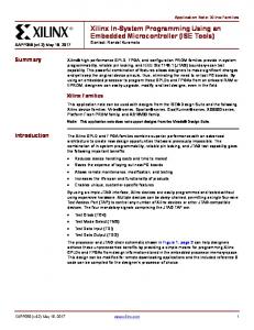
Figure-1 The OVSF codes are arranged in a tree structure
The paper is structured as follows: Section 2 illustrates about representation of the OVSF code. Section 3, describes methods for generation of OVSF code. In Section 4, we show the JTAG co-simulation based model with Xilinx system generator and evaluate our results with the serial architectures in section 5 to add validity to the theoretical results. Finally in section 6 we concluded our results. II. THE OVSF CODE REPRESENTATION In universal mobile telecommunication system (UMTS) the channelization code Cch, SF, N is uniquely described by two numbers: the spreading factor SF in the range [4 512] and the identification (ID) number N ∈ [0, SF – 1]. 2 9 The spreading factors vary from [2 - 2 ] in frequency 2 4 division duplex to [2 - 2 ] in time division duplex [5-6]. The OVSF codes can also be defined recursively by a tree
structure such that at each level in the code tree defines channelization codes of length SF as shown in Figure 1. If [C] is a code length 2 d at depth d in the tree, where the root has depth 0, two branches leading out of C are labeled by the sequences [C C] and [C -C], which have length 2d+1. Another one is Matrix representation as the rows of an Nby-N matrix, CN, which is defined recursively as follows. First, define C1 = [1]. Next, assume that CN is defined and let CN(k) denote the kth row of CN. Define C2N by Figure 2.
Figure-2 Matrix Representation for OVSF codes
I. Using LUT The method using LUT for OVSF code generation makes codeword by decoding spreading factor and code index. It is able to make codeword quickly but needs relatively large memories to store all codewords. It needs L2 bits of memory to make code word with SF of its length L = 2N. II. Using Logic gates The codeword [b1 ,b2 ,b3 ,b4 ... bl ] whose length is L = 2N has the code index [a1 ,a2 ,a3 ,a4 ... al ] whose length is N. Each codeword is generated by XOR operation of code index based on Hadamard Transform. So, we can get a codeword by positioning XOR gates parallel as shown in Fig. 4. To generate the codeword with SF L = 2N, it needs (2N -N-1) XOR gates and (N) NOT gates. Therefore, to make OVSF code with SF=512, it requires 502 XOR gates and 9 NOT gates [7].
Note that CN is only defined for N a power of 2. It follows by induction that the rows of CN are orthogonal. The codes at depth d in the tree are the rows of the matrix CN, where N = 2d. The two OVSF codes are orthogonal if and only if neither code lies on the path from the other code to the root. Since codes assigned to different users in the same cell must be orthogonal, this restricts the number of available codes for a given cell. For example, if the code C41 in the tree is assigned to a user, the codes C10, C20, C82, C83, and so on, cannot be assigned to any other user in the same cell as shown in Figure 3. .
Figure-4 Codes generator using Logic gates
III. Using Binary Counter This paper uses counter method for generating real time hardware implementation of OVSF codes and this structure requires (N +1) input XOR gate , N two input AND gate and N bit counter to generate codeword with SF L = 2N [9].
Figure-3 OVSF codes restriction for new code assignment
III.
METHODS FOR OVSF CODE GENERATION
The generation of the OVSF channelization codes is divided in two first is parallel code generation and second is serial code generation. The methods used for parallel generation is using Logic Gate or Look-Up-Table (LUT) whereas serial generation is using Counter. Since these methods have different performance depending on SF’s optimization is essential for the code generator structure.
Figure-5 Code generator using Binary Counter
The output chip sequence will be represented in the binary, since binary set has values between {+1, –1}, while digital CMOS logic operates on the set {0, 1}. The mapping {“+1” to “logic 0”} and {“–1” to “logic 1”} is therefore adopted as a convention. We have observed that smaller the SF we choose faster the data rate we get at the output. Table 1 and Fig. 6 shows change in data rate by varying various values of S.F. Table-I Data Rate with different Code Length
The maximum synthesized frequency corresponds to ~ 470 MHz with minimum period 2 ns which is lesser than delay per chip for WCDMA i.e. 260 ns [12]. Table 2 and 3 shows the synthesized delay and area consumption on FPGA. Table II Shows the Simulated Delays for OVSF Codes
S. No.
Parameter
Values
1
Minimum period
2.133 ns
Serial Number
Code Length (In Chips)
WCDMA Downlink Data rate
2
Min input arrival time before clock
2.580 ns
1 2 3 4 5 6 7 8
4 8 16 32 64 128 256 512
1.92 Mb/s 960 kb/s 480 kb/s 240 kb/s 120 kb/s 60 kb/s 30 kb/s 15 b/s
3
Maximum output time req. after clock
4.921 ns
4
Maximum combinational path delay
5.439 ns
Figure-6 Effect of code length on data rate for (a) a code of length 4 Chips (b) a code of length 8 chips (c) a code of length 16 chips.
IV.
Table III Device Utilization Summary for Genesys Board (DIGILENT)
V. RESULTS
IMPLEMENTATION OF OVSF CODE
The design using counter requires less additional hardware and implemented using D flip flop Fig. 5. A SF register, holding the required spreading factor, controls the counter cycle, while the index register controls the specific OVSF code. This separation of the high level parameters SF and N provides modularity of the circuit blocks when multiple OVSF codes are generated. The entire design is reconfigurable using parameterized variable i.e. SF. System Generator supports a black box block that allows RTL to be imported into Simulink and co-simulated with either ModelSim or Xilinx ISE Simulator. Black Box approach provides the largest degree of flexibility, at the cost of design complexity. We can interface any processor HDL into a System Generator design using it. All ports and buses on the processor can be exposed to the System Generator diagram, and we are free to engineer the required connectivity between the processor and other System Generator blocks. The VHDL code we write is finally embed inside the black box for simulation. Once the design is verified, a hardware cosimulation block can be generated and then will be used to program the Virtex-5 device (XC5VLX50T-1ff1136) FPGA for implementation [10][11]. The bit stream download step is performed using a JTAG cable.
The implementated design does not require any script or test bench since the model is MATLAB based all the test inputs are fulfilled externally through MATLAB simulink blocks. The fig. 8 shows that design. The fig. 8 also shows that JTAG co-simulation box which is required for FPGA implementation. Modelsim symbol in figure call the modelsim when we trigger run in MATLAB.The behavioural and post simulation are done by Mentor Graphics ModelSim tool as shown in Fig. 9. Test results from MATLAB based Scope is shown in Fig. 10 & 11. The area consumption is shown by slices and LUT (Look up Table) and Flip-flop that is given in Table 3 whereas delay and frequency estimation is given in Table 2.
Figure-7 System Generator for DSP Platform Designs
Figure-8 System Generator model for generation of HW-SW Co-simulation for OVSF Codes
Figure-9 Simulated Waveforms of OVSF Codes in ModelSim
Figure-10 Simulated Waveforms (for Verification) of OVSF Codes in MATLAB
Figure-11 Simulated Waveforms (for verification) in WAVESCOPE of System Generator
VI. CONCLUSIONS In this paper, the Parameterized OVSF code is implemented with maximum synthesized frequency i.e. 470 MHz. This flexibility is essential for UMTS transceivers, since signals of variable content and data rate requirements can be transmitted or received by changing the number and spreading factors of the channelization codes as specified by the 3GPP standard for WCDMA FDD/TDD system with maximum SF= 512. The MATLAB based System generation Co-simulation results shows that design can meet timing specification without any constraints from the critical path delay of the synthesized circuit i.e. 2 ns which is significantly smaller than chip duration i.e. 260 ns for WCDMA standard. VII. ACKNOWLEDGMENT The authors would like to thank Mrs. Anu Gupta, HOD, Department of EEE, BITS-Pilani and CSIR (MHRD, DELHI). This work is published with the support of CSIR (MHRD, DELHI) SRF Fellowship. VIII. [1] [2]
[3]
[4]
[5] [6] [7] [8] [9] [10] [11]
REFERENCES
J. Mitola III, “Software radios - survey, critical evaluation and future directions,” Telesyst. Conf., 1992. NTC-92., National, pp. 15–23, May 1992. A. Baier, U. C. Fiebig, W. Granzow, W. Koch, P. Teder, and J. Thielecke.”Design Study for a CDMA-Based Third-Generation Mobile Radio System.” IEEE Journal on Selected Areas in Communications, Pp. 733– 743, May 1994.
[12]
R. Fantacci and S. Nannicini. “Multiple Access Protocol for Integration of Variable Bit Rate Multimedia Traffic in UMTS/IMT-2000 Based on Wideband CDMA”, IEEE Journal on Selected Areas in Communications, Pp.1441–1454, August 2000. Y.S. Chen, T.L. Lin,” Code Placement and Replacement Schemes for WCDMA Rotated-OVSF Code Tree Management”, IEEE Transactions on Mobile Computing, Pp. 224 – 239, January 2006. B. D. Andreev, E. L. Titlebaum, E G.Friedman,” Orthogonal Code Generator for 3G Wireless Transceivers”, GLSVLSI’03, Proceedings of the ACM, Pp. 229 – 232, April 2003. S.Kim, M.Kim, C.Shin ,J.Lee ,Y.Kim ,"Efficient Implementation of OVSF Code Generator for UMTS Systems", PacRim 2009, IEEE Pacific conf.,Pp. 483 – 486, August 2009. Jhong Sam Lee, Leonard E. Miller, “CDMA Systems Engineering Handbook”, Artech House 1998. D.M. Baek, K.D. Joh, J.U. Kim, “Real-Time Processing of a Software Defined W-CDMA Modem”, IEEE Vehicular Technology Conference, Pp. 1959 - 1962, September, 2004. Rintakoski. T, Kuulusa. M, Nurmi. J, “Hardware Unit for OVSF/Walsh/Hadamard Code Generation”, System-on-Chip International Symposium on,Pp. 143 – 145, November 2004. Andrew Richardson: WCDMA Design Handbook. Cambridge University Press, 2005. Xilinx System Generator User's Guide, www. Xilinx.com. Available: [online] http://www.3gpp2.org/public_html/specs/c.s0002d_v1.0_021704.pdf, Digilent FPGA Board user’s guide. Available: [online] http://www.digilentinc.com/Products/Detail.cfm?Prod=GENESY S