PACKET-BY-PACKET RADIO RESOURCE MANAGEMENT BY MEANS OF DYNAMIC SINGLE FREQUENCY NETWORKS Magnus Eriksson Royal Inst. of Technology Dept. of Signals, Sensors and Systems S-851 70 Sundsvall, Sweden E-mail:
[email protected]
Abstract By combining a cellular system with the terrestrial digital video broadcasting system (DVB-T), wide-area asymmet ric Internet access can be achieved, with a downlink peak bit rate of 10-20Mbps. In this paper, we study dynamic resource management on a packet-by-packet basis for this broadband downlink. A model for best-effort traffic is proposed, which simplifies the evaluation of maximum throughput and fairness. Dynamic Single Frequency Networks (DSFN) are evaluated, which exploits the macrodiversity capability of the OFDM modulation scheme. The transmitters are divided into single frequency networks (SFNs), i.e. groups of transmitters that send the same in formation at the same channel frequency simultaneously. An algorithm changes the SFN grouping from timeslot to timeslot, and schedules the packets. DSFN is a way of introducing timeslots and Dynamic Channel Allocation into DVB-T, without keying of the transmitter power. Thus, receiver and transmitter circuits existing on the market today can be used, and only software modifications are required. A spectrum efficiency of 0.45 bit/s/Hz/site is achieved with omni-directional antennas under certain conditions. This is a capacity improvement of 170% in comparison to a Fixed Channel Allocation solution with static handover.
Introduction Popular Internet applications, such as WWW, Internet radio and thin clients, are characterized by asymmetric communication, i.e. much higher data rate to the terminal host than from it. Especially in mobile wireless communication, the limited battery capacity makes high uplink data rates less interesting than high downlink data rates. However, mobile communication systems for wide-area coverage (including GSM/GPRS and WCDMA) are not designed with asymmetric communication in mind, since
Youshi Xu Mid Sweden University Dept. of Information Technology S-851 70 Sundsvall, Sweden E-mail:
[email protected]
they use frequency division duplex (FDD), and the uplink and downlink frequency bands have equal width. To increase the downlink capacity in the cellular packet radio system GPRS, a wideband Orthogonal Frequency Division Multiplex (OFDM) supplemental downlink is proposed in [1]. The proposal supports 2-5 Mbps of peak bit rate in large cell environments, and 10Mbps in microcellular environ ments. The OFDM modulation is chosen because of its ability to combat inter-symbol interference (ISI) due to multi-path propagation, without the need of complex equalization. A more evolutionary approach is to use broadband widearea OFDM radio technology existing on the market today, instead of inventing a new air interface. The Digital Audio Broadcasting (DAB) system Eureka 147 [2] has a considerable coverage ni Europe, Canada and Australia. The Terrestrial Digital Video Broadcasting system (DVB-T) [3] is rapidly expanding in Europe and Australia. DAB can offer a net bit rate of 1.2Mbps. DVB-T offers 5 to 30 Mbps net data rate, depending on modulation and coding scheme. For technical details, see table 1. The EU ACTS project MEMO (Multimedia Environment for MObiles) [4] has delivered a complete proposal for turning DAB into a cellular system by combining it with the cellular telecommunications system GSM. The SABINA project (System for Asymmetric Broadband INternet Access) [5] is initiated by the Swedish national broadcasting company Teracom AB, and aims at combining DVB-T with GSM. A SABINA pilot implementation has demo nstrated downlink data rates of 10Mbps in mobile environments, and 15-20Mbps data rate is expected. A major challenge in the design of cellular systems is to achieve high spectrum efficiency (useful bit rate per base station site and Hz) by means of high channel reuse, but avoid co-channel interference. Our opinion is that the success of DVB-T as a wide-band downlink for wireless
DAB
DVB -T
Adopted 1995 1997 Net bitrate per 1.2 Mbps 4.98 - 31.67 Mbps channel: Channel separation About 1.7MHz 8MHz Freq. range of 174–240MHz , 470-790MHz today’s receivers: 1452–1492MHz. No of OFDM sub- 192, 384, 768 or 1705 or 6817 (the 2K and carriers: 1536 8K modes) Modulation: DQPSK QAM, 16QAM or 64QAM Forward Error Convolutional Inner convolutional coding Correction (FEC) coding with code with code rates 1/2, 2/3, 3/4, coding: rates 1/4, 3/8, 1/2 5/6 or 7/8. Outer or 3/4 RS(204,188,t=8) coding. Table 1: Technical details for the DAB and DVB-T standards.
Internet access depends on if the spectrum efficiency is comparable with state-of-the-art cellular systems. The Radio Resource Management (RRM) in today’s MEMO specifications for DAB is based on Fixed Channel Allocation (FCA), with Frequency Division Multiple Access (FDMA), static handover criteria (i.e. static cell formations) and no Power Control (PC) [6, 7]. All DAB transmitters are always sending, irrespectively of if they have data to send or not. The radio resource management (RRM) functions for DVB-T are not yet designed in the SABINA project, but are expected to be a further development of MEMO [6]. A substantial improvement of the spectrum efficiency in MEMO is expected with dynamic RRM techniques, such as Dynamic Channel Allocation (DCA), link adaptation (i.e. change of modulation scheme and forward error correction coding) and traffic adaptive handover (transmitter to terminal assignment). The aim of this study is to propose and evaluate dynamic RRM schemes for the DVB-T downlink that can be introduced without extensive changes of the DVB-T standard. They should only require modification of micro-controller programs and other software in transmitter and receiver equipment existing on the market today. Dynamic RRM require that RRM parameters, such as channel allocation, modulation and coding, can be changed at certain time instants. This is facilitated by the introduction of non-overlapping timeslots in the DVB-T system. The RRM parameters can be changed between the time slots, but not during the timeslots. In most modern cellular systems, the interference fluctuations is handled by so-called interference averaging, i.e. frequency hopping or CDMA. This is not possible in DVB-T, without a major change of existing hardware. However, that should not be considered as a problem. On
the contrary, it was shown by Pottie [8] that interference avoidance, by Dynamic Channel Allocation and power reservation, can perform a factor 2 to 3 better spectrum efficiency than interference averaging techniques. DCA requires centrally controlled base stations. That is especially alluring since we only deal with the downlink, and a centralized system can gather information about the destinations of all data packets in the queues without the need of additional signaling. The OFDM downlink proposal mentioned in the beginning of this paper is based on a Dynamic Packet Assignment (DPA) scheme [1]. DPA performs radio resource reservation for each data packet individually. It combines DCA and power reservation with statistical multiplexing, i.e. data packet scheduling. The mobile terminals measure the path loss from the nearby base station transmitters about once per second, and reports this to the base stations via the GPRS back channel. A scheduling scheme is performed locally in each base station transmitter, aided by a fast backbone network connecting the base stations. A drawback with this DPA scheme is that it requires several Signal-to-Interference ratio (SIR) calculations per data packet. In our previous work [9, 10], we present a similar concept, which we call Packet And Resource Plan Scheduling (PARPS). PARPS reduces the combined problem of statistical multiplexing, channel allocation, power control, link adaptation and soft handover to a scheduling problem. In contrast to the above DPA algorithm, PARPS can perform transmitter-to-receiver assignment on a packet-by-packet basis, i.e. fast traffic-adaptive handover. For exa mple, if a terminal is midway between two transmitters (base stations), some of the packets may be transferred over the first transmitter, and the others over the second, depending on the traffic load to other terminals. SIR calculations are only needed when a terminal becomes active or moves. The introduction of timeslots and dynamic RRM are afflicted with practical problems in today’s DVB-T standard, and may require changes of existing hardware. For exa mple, since the information about the modulation and coding reconfiguration in the next so called super-frame is sent by means of Transmission Parameter Signaling (TPS) subcarriers during present super-frame. The TPS information regarding a certain super-frame may be lost, if the nearest transmitter signal was removed or sent with reduced power during previous super-frame.
The concept of dynamic single frequency networks We propose a new approach to the above problem, which we call Dynamic Single Frequency Networks (DSFN). This is a way of introducing timeslots and DCA, without keying
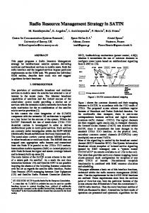
Figure 1: A simple example.
while instead of an abrupt switching from the first to the second transmitter. Soft handover is robust towards sudden radio shadowing of one of the transmitters, in comb ination with slow path loss measurements.
Rx3
Top: Coverage map.
Rx1
Rx2 Tx2
Tx1 Rx4
Below: Data packet schedule, stating the packet destinations.
Rx5 Timeslot 1
Timeslot 2 t
Tx1: Rx1 Rx1 Rx1 Rx1 Rx3 Rx4 Rx3 Rx4 Tx2: Rx2 Rx2 Rx2 Rx2 Rx3 Rx4 Rx3 Rx4
of the transmitter power. All transmitters continuously transmit at full power. The transmitters are divided into Single Frequency Networks (SFNs), i.e. groups of transmitters that send the same information at the same channel simu ltaneously. The OFDM modulation scheme avoids self-interference due to this macro diversity. By having big SFNs (with a large number of transmitters), co-channel interfe rence is avoided, but the spectrum efficiency is reduced. The term DSFN implies that the SFN grouping is changed from timeslot to timeslot. A simple example: (See figure 1.) A system consists of two transmitters, Tx1 and Tx2, and five receivers, Rx1 to Rx5. During the first timeslot, Tx1 and Tx2 send different information, which only can be received within the two circles, since the co-channel interference level is too high outside the two circles. The schedule shows that during timeslot 1, Tx1 and Tx2 send data packets destined to terminal Rx1 and Rx2 respectively. During next timeslot, both transmitters send the same information simultaneously, i.e. they are grouped to an SFN. The SFN covers the whole ellipse, and can therefore send data packets destined to terminal Rx3 and Rx4. Terminal Rx5 cannot be covered, and is in a state of outage, because of noise or interference from external transmitters outside the system. During the first and second timeslot, the spectrum efficiency is R/2B and R/B bps/Hz/transmitter respectively, where R is the transmitter bit rate, and B is the channel bandwidth. The spectrum efficiency η averaged over the whole period is 3R/4B. DSFN can be characterized as a soft handover technology, meaning that when a terminal mo ves from one transmitter towards another, both transmitters sends to the terminal a
DSFN simplifies the problem of packet-by-packet resource management substantially. Since all transmitters send continuously using constant power, all transmitters that are not assigned to a certain terminal can be considered as interferers. Hence, the interference level to a certain re ceiver can be analyzed without knowledge of the traffic assigned to other transmitters. The terminal measures the path loss from all neighboring transmitters by means of orthogonal transmitter identifica tion codes. Based on these measurements, a distributed algorithm executed in each terminal identifies the minimum SFN, i.e. the set of transmitters that is required for sufficient SIR. The terminal reports the minimum SFN to a central transmitter controller. Note that SIR calculations are only performed locally in the terminals. A centralized DSFN scheduling algorithm organizes the transmitters into SFNs separately for each timeslot and frequency, selects transmission scheme (modulation and forwards error correction coding) for each SFN, and assigns data packets to SFNs, timeslots and channels. However, in this paper the scheduling schemes do not choose transmission scheme and channel. Receiver to frequency channel assignment is assumed to be handled by a separate algorithm.
System model The system consists of a set TX of NTx centrally controlled and synchronized transmitters, sending information to the set RX of NRx receivers (terminals), using the same frequency channel. The power i Î TX = {1,2, K , NTx } , received
from by
transmitter receiver
j Î RX = {1,2, K, N Rx } , is denoted Pi,j . Due to shadow fading, 10log10 Pi,j is normal distributed with standard deviation σS dB, and average æ P F ÷ö çç i i , j ÷ é ù E10log , 10 Pi , j ûú = 10log10 ç a ÷ ëê çè di , j ÷÷ø
(1)
where Pi is the transmitted power level from transmitter i, d i,j is the distance, Fi,j depends on the antenna gain, the antenna heights and the carrier frequency, and α is the propagation coefficient.
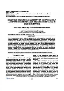
empty set M j ,m . Extend M j ,m by the non-used transmitIn our simulations, α=4 and σS =8dB. Pi Fi,j is a constant, since we only consider omni-directional antennas and no power control. The transmit ters are positioned on Ntyres concentric hexagonal tyres, so that each transmitter has the same distance to Figure 2: Example of 37 transmitters positioned its six closest neighbors. See the example in figure 2. on Ntyres = 3 hexagons. Only seven of the DVB-T transmission schemes are considered: QPSK modulation with code rate 1/2, QPSK 2/3, 16QAM 1/2, 16QAM 2/3, 64QAM 1/2, 64QAM 2/3 and 64QAM 5/6. These are referred to as scheme number m=1 to 7. The different transmission schemes require different SIR. We use the SIR thresholds γm given in Annex A of [3] for bit error rate 10-11 after the error correction, for a Rayleigh fading model of the multi-path propagation.
Single Frequency Networks A Single Frequency Network (SFN) is a set of one or several transmitters sending the same information simultaneously over the same frequency channel. The signal-tointerference ratio (SIR) at receiver j, averaged over all OFDM sub-carriers, is according to [11]:
G = j
å
iÎTX \ U j
åPw
iÎU j
P
i, j
+
i, j i , j
åP
iÎU j
i, j
(1 - w ) + N ,i j
» 0
åP
iÎU j
å
i, j
iÎTX \ U j
P
,
(2)
i, j
where Pi.j is the power from transmitter i received in terminal j, U j Í TX is the set of U j ³ 1 transmitters in the SFN (the useful signals) assigned to receiver j, TX \ U j is the set of co-channel interferers, N0 is the noise power including signals from external non-centrally controlled transmitters, and wi , j Î [0,1] is a weighting factor depending on the ISI. In our simulations, we neglect the noise and ISI. This leads to the approximation in the right term above.
A distributed algorithm for identification of the minimum SFN The minimum SFN of receiver j and transmission scheme m is the minimum set M j , m Í TX of transmitters assigned to the receiver, such that the required SIR is achieved. We propose the following distributed algorithm for the identification of the minimum SFN M j, m : Start with an
ter that gives highest received power iteratively, until the required SIR threshold γm is achieved. If the terminal re quires a bigger SFN than the number of centrally controlled transmitters, the algorithm indicates that the terminal is in a state of outage by setting M j, m to the empty set. The algorithm pseudo code follows: M j ,m := Æ do
if M j, m ¹ TX
M j ,m := M j, m È argmax Pi, j i ÎTX \ M j ,m
else { M j ,m := Æ break while
å
j Î M j,m
Pi, j
} æ çç çç Pt o t, j - å Pi, j j Î Mj ,m è
÷÷ö ÷÷ < gm ÷ø
The function argmaxx i is the index i of the largest elei
ment xi , or the index to the first of several equal elements with the largest value. Ptot,j is the total received power in transmitter j, i.e. the sum of the nominator and denominator of (2). If link adaptation should be supported, the algorithm is repeated for each transmission scheme m. A simple proof shows that the algorithm minimizes the SFN size for a required SIR. Note that this is not necessarily the same thing as maximizing the spectrum efficiency.
Traffic model and performance measures Only best-effort traffic is considered, i.e. communication without differentiated priorities or quality of service guarantees. Flat rate, or small variable charge, is assumed. An active terminal (in the literature sometimes called a back -logged terminal) is a terminal with at least one data packet waiting in the system queues. During a period of terminal activity, a data burst is transferred to the terminal. A terminal that does not need all of the available capacity, will rapidly alternate between active and passive state. The active terminals are uniformly distributed, with a density of ω active terminals/transmitter. Our aim is to analyze the capacity (the maximum throughput summarized over all receivers in the system) in bps, the spectrum efficiency η (the capacity divided by the number of transmitter sites and radio frequency bandwidth) in bps/Hz/transmitter site, and the fairness.
Dynamic RRM may cause absurd unfairness, if it is designed only with the objective to maximize the capacity (and by that the average bit rate per terminal). For exa mple, if several terminals were contending about the same transmitter, the capacity would be maximized if the least “expensive” terminal (e.g. the terminal at shortest distance from the transmitter) were allowed to use the whole resource without sharing it with the others. On the other hand, equal resource sharing is not desirable. We do not want to prevent a terminal from using a free timeslot because it has already achieved higher bit rate than other terminals, although it is not possible to assign the timeslot to another terminal. We strive at max-min fairness [12], which is a widely accepted compromise between the two above extreme strategies for computer networks. Max-min fairness implies that the first priority is to maximize the lowest bit rate that an active terminal achieves, the second priority is to maximize the second lowest bit rate, etc. We propose a combined performance measure of fairness and spectrum efficiency, which we call the fairly shared spectrum efficiency in bps/channel/transmitter, and define :
F (w) @
é ù E ê N Rx min r j ú , j ÎRX NTx B ë û 1
(3)
where rj is the average bit rate that terminal j acquires during the data burst in a maximum throughput situation, and B is the channel bandwidth.
These assumptions are reduced to a steady-state traffic model with a constant set of ωNTx stationary active terminals in each simulation, i.e. no data bursts are initiated or finished during the simu lation. All IP packets are assumed to have equal lengths of 1500 bytes, which is the maximum payload of Ethernet frames. The timeslot entity is assumed to be a so-called OFDM frame, with duration 17.136 milliseconds1 . The seven transmission modes m can transfer Rm = 7, 10, 15, 20, 23, 30 and 38 IP packets per timeslot respectively 2 . The traffic load due to TCP automatic repeat request retransmissions is neglected, since the SIR thresholds γm used in the minimum SFN identification are pessimistic.
Two centralized DSFN scheduling algorithms Each receiver j reports the minimum SFN M j ,m to the central system controller. A centralized scheduling scheme can assign data packets destined to terminal j to timeslot t and SFN U j . [13] shows that the max min-fairness objective described above can be achieved by employing fair queuing. This comprises that there is a separate first-come first-served data packet queue for each receiver in the central control unit. Lj denotes the number of equally sized packets in the queue destined to receiver j. The scheduling algorithm is performed once per timeslot.
It is hard to identify the capacity (the maximum throughput) in conventional packet delay vs. load analysis without including flow control in the model. The simulations have to be repeated for diffe rent traffic load levels, until the point of overload is identified with sufficient accuracy. A large number of packets have to be handled by the system queues near this point. This leads us to the following simplified traffic model: Perfect flow control is included in the model, such that a new packet destined to a terminal is delivered to the system for each packet that is transmitted to the terminal. The terminals consume as much data rate as they are allowed. Thus, all transmitters that are assigned to at least one active terminal are in a maximum throughput situation. When several RRM schemes are compared, the user behavior is assumed to be affected by the performance of the RRM schemes in the following way: The arrival intensity and the duration in time of the data bursts are not changed, but the amount of transferred information during a burst is proportional to the data rate that the user acquires. Thus, the density ω is independent of the RRM scheme.
The input parameters to the scheduling algorithm are: the set of centrally controlled transmitters TX; the transmission scheme m; the minimum SFNs
M j ,m ; the queue
lengths Lj; the maximum number of packets per timeslot Rm ; and the set RX of active receivers not in outage, i.e.
RX @ { j : L j > 0 Ù M j ,m ¹ Æ} .
1
The DVB-T 2K mode (i.e 1512 OFDM sub-carriers) with 1/8 OFDM guard interval is assumed. 2 This is a consequence of the following assumptions: An integer number of IP packets can be transferred during a timeslot. The MPEG multiprotocol encapsulation (MPE) protocol can transfer each IP packet by a non-integer number of MPEG packets, each with 184 bytes payload. To avoid that an MPEG packet is divided between several timeslots, the convolutional outer interleaving in DVB-T is modified to block interleaving by a simple reordering of the information bytes. The resynchronisation time of the convolutional decoder in the beginning of each timeslot is neglected.
The output parameters of the scheduling algorithm are: number of scheduled data packets NP2Rxj to each receiver during the timeslot; the SFN to receiver assignment vector
ìïn, if receiver j is assigned to SFN number n, SFN 2Rx j @ ïí ïïî0, if receiver j is not assigned to this timeslot; and the SFN to transmitter assignment vector
(
Introductory simulations show that it is beneficial to schedule the terminals with biggest minimum SFN first. An intuitive explanation is that it is easier to pack a knapsack efficient if we start with the big objects, and put small objects in spaces in between. Thus, the SFN size also affects the scheduling priority in the algorithms. The scheduling may not be efficient if we always use the minimum SFN to each receiver, such that U j = M j, m . For example, it may be beneficial to send packets to two terminals j1 and j2 with similar minimum SFNs during the same timeslot. The scheduling scheme should combine the two minimum SFNs, such that U j1 = U j2 = M j1, m ∪ M j2 ,m . However, introductory simulations indicate that for the steady-state traffic model with unlimited number of packets to each terminal, U j = M j, m is the most efficient solution. Combination of SFNs is only advantageous when the queue to a terminal becomes empty before the timeslot ends, and there is room for more packets in the schedule to a similar SFN during the same timeslot. Because of this, the scheduling algorithms have two phases. Phase 1 only assigns terminals with disjoint or equal minimum SFNs. If a queue becomes empty before phase 1 has come to an end, phase 2 will be carried out, which tries to combine several minimum SFNs. Note that phase 2 can not be evaluated for our traffic model. In this paper, phase 2 is only documented for algorithm A. Algorithm A counts the number of packets Cj that each terminal j has sent. The algorithm iteratively tries to schedule a packet to the receiver that has firstly minimum counter value Cj ¸ and secondly biggest minimum SFN. When a terminal j enters the active state, its counter is set to
j ' ÎRX \ j
(4)
Thus, a packet from a new data burst achieves highest priority. A terminal that recently left the active state is prevented from getting a more advantageous place. To avoid counter overflow, all counters may be adjusted, e.g. after each timeslot, according to:
ìïn, if transmitter i is assigned to SFN n, SFN 2Txi @ ïí ïïî0, if transmitter i is not used. Two modified fair queuing algorithms are presented here. Algorithm A starts to schedule the terminals that have acquired lowest bit rate since they became active, while algorithm B gives scheduling priority to terminals that have waited long time since last packet.
)
C j := max C j , min C j ' ,
C j := C j - min C j ¢ , j ¢ Î RX
"j .
(5)
Pseudo code for algorithm A: SFN2Txi := 0, ∀ i ∈ TX NP2Rxi := 0, ∀j ∈RX NP2SFNn := 0, ∀n ∈ TX NSFN := 0 1 α := 1 + max M j, m − min M j , m j∈RX
j∈RX
phase2_flag := false // Phase 1: A := RX while A ≠ ∅
(
j := argmin C j ' − α M j ', m j '∈A
)
if NP2SFNSFN2Txi = Rm for any i ∈ M j , m A := A\j else { if SFN2Txj´ = 0, ∀j ' ∈ M j ,m { NSFN := NSFN + 1 n := NSFN SFN2Txi := n, ∀i ∈ M j ,m } else n := SFN2Txi for one of the elements i ∈ M j , m if (( n n ≠0) and (SFN2Txi = n for any i ∈ M j , m ) and (SFN2Txi ≠ n for any i ∈ TX \ M j ,m )) { SFN2Rxj := n NP2Rxi := NP2Rxi + 1 NP2SFNn := NP2SFNn + 1 Cj := Cj + 1 Lj := Lj - 1 if Lj = 0 { A := A\ j phase2_flag := true } else A := A \j } } // Phase 2: if phase2_flag A := RX
{
while A ≠ ∅
(
{
j := argmin C j ' − α M j ',m j '∈ A
NSFN := NSFN + 1 n := NSFN SFN2Txi := n, ∀i ∈ M j ,m
)
else n := SFN2Txi for one element i ∈ M j , m
if ((Lj = 0) or (NP2SFNSFN2Txi = Rm for any i ∈ M j , m ))
if (( n n ≠0) and (SFN2Txi = n for any i ∈ M j , m ) and (SFN2Txi ≠ n for any i ∈ TX \ M j ,m )) { SFN2Rxj := n NP2Rxi := NP2Rxi + 1 NP2SFNn := NP2SFNn + 1 Tj = t + NP2SFNn /Rm Lj := Lj - 1 } else r Remove the element with value j from A
A := A\ j else { N := U SFN 2Txi i ∈M j ,m
if N\0 consists of one element n := N\0 SFN2Txi := n, ∀i ∈ M j ,m SFN2Rxj := n NP2Rxi := NP2Rxi + 1 NP2SFNn := NP2SFNn + 1 Cj := Cj + 1 Lj := Lj - 1 }
{
}
}
} } } The function argsort denotes the ascending sort order indices vector. For example: argsort(10 40 30) = (1 3 2).
} }
Simulation results Algorithm B is based on a timestamp Tj , which states during which timeslot terminal j was scheduled last time. If no packets have been sent to receiver j, Tj is the instant when the terminal entered the active state. The algorithm tries to schedule one packet to every active terminal, in a roundrobin fashion, until no more packets can be scheduled. Before every timeslot, the terminals are sorted to firstly, prioritize long waiting time, and secondly, prioritize large SFNs. Pseudo code for algorithm B: t := t + 1 SFN2Txi := 0, ∀ i ∈ TX NP2Rxj := 0, ∀j ∈RX NP2SFNn := 0, ∀n ∈ TX NSFN := 0 1 α := 1 + max M j, m − min M j , m j∈RX j∈RX r A := argsort T j ' − α M j ', m j '∈ RX
(
)
r while A is a non-empty vector { r for j = each element in A { if ((NP2SFNSFN2Txi = Rm for any i ∈ M j , m ) or (Lj = 0)) r Remove the element with value j from A else { if SFN2Txj´ = 0, ∀j ' ∈ M j ,m {
We only summarize the achieved results. Results indicate that the outage probability is highly sensitive to external interferers (transmitters outside the centrally controlled system). This should be further analyzed. In the following, a model with no noise and no external interferers (i.e. transmitters outside the centrally controlled system) is considered. In this model, there is no outage, since a terminal can be assigned to all transmitters, corresponding to infinite SIR. The bigger the system (i.e. the higher NTyres), the lower spectrum efficiency in bps/Hz/site is performed, since big systems suffer from high interference level. The two scheduling algorithms are analyzed by means of the steady-state traffic model. For the worst-case scenario with high density (ω=5 active receivers per transmitter), and a big system (consisting of 12 hexagonal tyres of transmitters), the highest spectrum efficiency is
maxη m =0.45 bps/Hz/site. m
This is achieved for the transmission scheme 64QAM with code rate 2/3, and algorithm B. The fairly shared spectrum efficiency in the same case is F = 0.07 bps/Hz/site. The results show that algorithm B generally gives slightly higher spectrum efficiency η than A, but A gives higher fairly shared spectrum efficiency F(ω), i.e. it is more fair.
Analysis of a static FCA system
References
A simplified model of the MEMO RRM applied on DVBT is evaluated for reference. Static handover is assumed, such that a terminal j is assigned to the transmitter i that gives maximum signal strength Pi,j . There are no timeslots. The required channel reuse factor Km for 2% outage is evaluated with analysis similar to [14] for each transmission scheme m, for a very large system. All transmitters are assumed to be in maximum throughput situation. The spectrum efficiency is estimated as
[1]
h = max m
Rm , Km B
[2]
[3]
(4)
where Rm is the transmitter useful data rate in transmission scheme m. The analysis results in a maximum spectrum efficiency of η = 0.17 bps/Hz/transmitter site. We have not studied the fairly shared spectrum efficiency F for this case.
Conclusions Dynamic Single Frequency Networks gives a capacity improvement of 170% in comparison to a Fixed Channel Allocation (FCA) solution with static handover. However, the results are strongly dependent on parameters such as interference from transmitters outside the centrally controlled system, and the number of transmitters in the system. From the min-max fairness criteria point of view, algorithm A should be chosen. Further improvement is expected if DSFN is combined with link adaptation, directional antennas and traffic adaptive SFN formations (to avoid using transmitters with high load). The algorithms should be further developed to handle non-equally sized data packets, as well as frequency channel allocation. Even higher performance is expected if we allow keying of the transmitter power (transmitter signal removal) and power control by means of schemes such as DPA and PARPS, but that require hardware modifica tions of receiver and transmitter equipment exis ting on the market today. The algorithms should be evaluated for a non-steady-state traffic model, for mobile terminals and for external cochannel interference. A major contribution of the study is that it indicates that DVB-T has potential for becoming an efficient radio interface for broadband Internet access, up to the standard with state-of-the-art cellular technology.
[4]
[5]
[6]
[7]
[8] [9]
[10]
[11]
[12] [13]
[14]
J. Chuang, et al, High-Speed Wireless Data Access Based on Combining EDGE with Wideband OFDM, IEEE Co mmunications magazine, Nov 1999. ETSI. Radio broadcasting systems; Digital Audio Broadcasting (DAB) to mobile, portable and fixed receivers, ETS 300401, May 1997. See http://www.etsi.org/broadcast/dab.htm. ETSI, Digital Video Broadcasting (DVB); Framing structure, channel coding and modulation for digital Terrestrial television (DVB-T), EN300744 v1.1.2, Aug 1997. See http://webapp.etsi.org/pda. W. Klingenberg, A. Neutel, MEMO: a hybrid DAB/GSM communication system for mobile interactive multimedia services, Third European Conference on Multimedia Applications, Services and Techniques ECMAST, Berlin, Ge rmany, 1998. ACTS, M. Andersson (Teracom AB) et al, MEMO/DVB-T Prototype. See http://memo.lboro.ac.uk/publicdeliverables/ds049.pdf ACTS, J. Ebenhard (Ericsson), Mobility Management, MEMO System Function Spec. SFS4 rev B, Dec 1998. See http://memo.lboro.ac.uk/specs/sfs4.pdf ACTS, J. Ebenhard (Ericsson), Mobility Management Protocol, MEMO Protocol Specification PS2 rev A, Dec 1998. See http://memo.lboro.ac.uk/specs/ps2.pdf. G. J. Pottie, System Design Choices in Personal Communications, IEEE Personal Comm., Oct 1995. M. Eriksson, H. Säterberg, The Concept of PARPS Packet and Resource Plan Scheduling, Proc. Multiaccess, Mobility and Teletraffic in Wireless comm. MMT’99, Venice, Italy, Oct 1999. See http://www.ite.mh.se/~mager/myresearch/mmt99.pdf. M. Eriksson, H. Säterberg, Dynamic radio resource management for interactive DVB-T and DAB, Radiovetenskap och kommunikation RVK’99, Karlskrona, Sweden, June 1999. G. Malmgren, Single Frequency Broadcasting Networks, PhD thesis, Dept. of Signals, Sensors and Systems, Royal Inst. of Technology, 1997. See http://www.s3.kth.se/radio/Publication/Pub1996 /GoranMalmgren1996_1.pdf . D. Bertsekas, R. Gallager, Data Networks, 2nd Edition, Prentice Hall, 1992. E. L. Hahne, Round-Robin Scheduling for Max-Min Fairness in Data Networks, IEEE Journal on Selected Areas in Communcations, Sept 1991. L. Ahlin, J. Zander, Principles of Wireless Communications, Studentlitteratur, 1998.