PACKET VIDEO FOR HETEROGENEOUS NETWORKS USING CU-SEEME T. Brown, S. Sazzad, C. Schroeder, P. Cantrell, J . Gibson Texas A&M University, College Station, TX ABSTRACT Software based desktop videoconferencing tools are developed to demonstrate techniques necessary for video delivery in heterogeneous packet networks.* Pyramidal compression, congestion avoidance, end-to-end delivery, and predictive rate control results are presented. 1. INTRODUCTION
Software implementations of video coders promote the design of novel schemes t h a t address packet video network issues. One such issue is bandwidth heterogeneity. Since users connect t o the Internet a t different bandwidths, it is particularly important t o accomodate each recipient of video with the best possible quality its connection will allow. In this work we have added a pyramidal coding scheme to the CU-SeeMe [l] video coder to generate a true multiresolution stream which we will call the “enhancement” layer. This allows an extra degree of customization t o each recipient’s network resources while providing compatibility with previously deployed systems using the standard 160x120 resolution CU-SeeMe stream as a base layer. In addition, there is a quality parameter that is used t o control the bit rate of the enhancement layer. Software-based, one-to-many videoconferencing tools have been developed t o test new ideas for congestion avoidance and efficient resource reservation. A key idea associated with pyramidal video is that enhancement layer packets are worthless if base layer packets are lost during network transmission. There are two approaches t o ensure that bandwidth is first allocated t o the base layer: either drop (or curtail in a unicast conference) the enhancement layer immediately upon packet loss, or give priority t o base layer packets and let modified IP routers absorb short term congestion. 2.
3
2
2
1
1
0
0
-1
-1
-2
-2
-3
-3
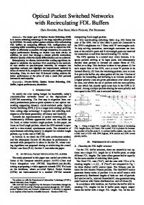
Figure 1: Mapping used in the lossy coding scheme
blocks. The challenge was t o encode these pyramidal difference blocks so that the average output bit rate for the enhancement stream would be below 60 kbits/s a t two frames per second. The uncompressed rate of the pyramidal difference stream is 768 kbits/s as the pixel differences are represented using 5 bits. To code the pyramidal difference blocks, two observations were noted. First, the pixel differences are distributed with a Laplacian-like density with a large peak about zero and rapidly decreasing tails. Using this ordering, a Huffman code was produced to represent the difference pixels. Statistics from simulation suggest that the average codeword length is 2.6 bits/difference. The other observation is that a typical 16x16 pyramidal block has long runs of difference values and this suggests that run length coding may be used t o exploit these runs. Initial development of the coder with the “Miss America” sequence showed promise when the pyramidal difference blocks were run length encoded. It was then found t h a t the higher level of detail in the “Salesman” sequence resulted in many unit length runs which greatly lowered the performance of the run length coding. It was apparent that it was not possible to losslessly encode the pyramidal difference blocks and satisfy the desired output bit rate constraint. Fig. 1 shows a mapping technique that was developed t o add a lossy component t o the run length coder. By mapping t o zero those differences close to zero, it is possible t o obtain significant reductions in the output bit rate while maintaining acceptable picture quality. This is achieved because the mapping effectively increases the run lengths that occur in a pyramidal difference block. There are several interesting features of this lossy run-
PYRAMIDAL COMPRESSION
CU-SeeMe provides a 16 level greyscale picture with a standard window size of 160x120 pixels. Two steps, conditional 8x8 block replenishment and lossless compression, are used in the CU-SeeMe video coding algorithm. In generating the enhancement stream, the conditional replenishment blocks are upsampled and then subtracted from the corresponding blocks in the true 320x240 resolution frame. This produces a set of pyramidal difference See http://www-mcnl.tamu.edufor more information
0-7803-3258-X/96/$5.00 0 1996 IEEE
3
9
I
Average Ouwut Rate
-
Figure 4: Rate vs Quality for Pyramidal stream at 2 f/s
Figure 2: Decoded frame from video sequence with q=O
The example has illustrated the effect of t h e quality ( q ) parameter on t h e bit rate of t h e enhancement stream and on the picture quality of the decoded video. Fig. 4 shows how the average bit rate for the enhancement stream varies with q. This single variable may be used t o control the bit rate of t h e enhancement stream from a high of over 100 kbits/s when q=O t o zero kbits/s when q=15. 3. PREDICTIVE RATE CONTROL
length coding scheme. First, it may be implemented with no computational overhead. This is because it is incorporated into the look up table that is used to compute the pixel differences. Second, it will be seen that the range of values about zero that is mapped to zero has a significant effect on the output bit rate. The effect of the lossy run-length coding on picture quality can be seen in Figs. 2 and 3. As these frames were generated from a real-time simulation, they contain coding artifacts due to the conditional replenishment. For q = 0, the picture has well defined features and the edges are sharp. However, the average bit rate of the enhancement stream is about 130 kbits/s at 2 frames/s which is prohibitively high.
An important issue in the network delivery of video d a t a is the need to maximize the quality of a video stream given a known quantity of network resources. With the increasing availability of ISDN services and even resource reservations for the Internet, links with pre-determined, known bandwidths are now available. Given information about t h e quantity of available resources, one important goal of a video-conferencing application should be t o provide t h e highest level of quality possible for that bandwidth. To this end, a mechanism was developed by which variable bit-rate (VBR), real-time video streams can be sent over a semi-constant rate network connection. A rate control mechanism is developed that dynamically adjusts the quality of the video encoding using a prediction mechanism t o obtain a nearly constant rate, thus allowing the algorithm t o make use of a high percentage of the constant rate network connection. Four basic assumptions were made in the design of the rate control mechanism. This first assumption is that t h e past is a reasonable guide t o the future in that past encoder outputs can be used t o predict future ones. Secondly, the VBR video encoder is assumed t o have an adjustable quality control parameter similar to our encoder described earlier. The quality parameter can adjust any facet of the
When q = 1 , there is no significant loss in clarity. When q = 2 , the bit rate is 37 kbits/s at 2 frames/s, and now a
video encoding Like the motion detection threshold or the coarseness of the DCT quantizer as long as t h e parameter
Figure 3: Decoded frame from video sequence with q=2
slight roughing of the edges becomes visible. The hair becomes slightly blurred as are the eyes, lips and the rest of the face. Despite this loss in small detail the picture as a whole is still quite clear.
allows for the graceful reduction of the video image as well as the resulting bit-rate. It was additionally assumed that
the frame rate is constant, with f frames being sent in every time interval, T . This assumption is not crucial, however,
10
550
500
-
450
-
400
-
--0.1
/
nvemge mob
....................... "%.
...../
-----
-
I
......
mixed
/'
.....
........ .......... .....
I 0.2
0.3
0.4
0.5
0.8
TA Weight
0.7
0.8
0.9
1
0
20
40
Bo
80
100
#me (wcond.)
120
140
180
180
200
Figure 5 : Reservation Efficiency/Over as a Function of a
Figure 6: Rate Controlled vs. Original Output a t 5 f/s
as the results should hold true for a variable frame rate, as well. Lastly, of all the video quality levels, the user is assumed t o have a preferred, target quality level, qt. Before each frame is encoded a determination is made of the best video quality t h a t can be used t o encode the remainder of frames in the current time period, r. The first frame of each time period is always encoded a t the target quality level. In order t o determine the best quality level a t which t o encode the next frame, the algorithm keeps a weighted timeaverage of past encoder outputs a t each video quality level, b[q]. After a frame, i , of size b,, is sent, the average bit-rate a t t h a t quality level is updated according to &[q] + b, * a &[,I * (1 - a)
in correctly predicting events in the near future. Similarly, E = -0.05 is the best choice for maximizing the bandwidth efficiency. Current techniques for fitting a VBR video stream into a semi-constant rate connection include picking the best video quality which keeps the peak rate of the video output below the connection rate. For the three test sequences this technique resulted in an average link bandwidth utilization of only 50%. Using the predictive technique, however, the average utilization rate rose t o 82% with only 0.04% of the total number of bytes exceeding the link capacity. T h e use of more of the available bandwidth resulted in an increase in video quality. The use of this mechanism can additionally be extended t o constrain the output rate of a stream t o a specified link capacity with great efficiency. Fig. 6 shows an uncontrolled image stream encoded a t q = 1 superimposed with a rate controlled version of the same input encoded a t qt = 1 for a link capacity of 8 kBytes/second.
+
where a represents the weight of the most recent sample in computing the average. As each frame in a time interval is encoded and sent t o the network, the total bit-rate for that time period is kept and compared with the target rate of the network connection multiplied by an error allowance, (1 E ) . In this manner the remaining available bandwidth in r can be determined and again used t o choose the best quality at which to encode the remaining frames. The success of this algorithm was measured in terms of three quantities: the percent utilization of the target bandwidth, the percentage of bytes in excess of the target bandwidth, and the overall quality of the resulting bit-stream. Since one of the goals of the algorithm is t o maximize the percent utilization of the available bandwidth while minimizing the percentage of bytes which exceed the target bandwidth, the figures below employ a measurement (E/O) of the bandwidth efficiency divided by the percentage of bytes in excess of the target rate. These results are based on a series of trials using the predictive rate control mechanism with our encoder for three different head and shoulders video sequences: one with very little motion (STILL), one with a good deal of motion (MOTION), and one marked by alternating periods of high and low motion levels (MIXED). As can be seen in Fig. 5, the success of the algorithm is maximized, on average, for a = 0.7. The high value of a represents a strong dependence on the recent encoder outputs
+
4. CONGESTION AVOIDANCE
Current implementations that use source-based bit-rate control with receiver feedback actually use it t o perform two functions. Not only is the scheme used for congestion avoidance, but at the same time it is used for improving the quality of service by reducing artifacts caused by packet loss. When this scheme is used in a conference with many participants, it can provide neither of these functions well for all of the participants. Ideally, the responsibility for each of these two functions in a multicast session should belong to two different mechanisms. Quality of service may be provided by changing the I P network layer t o give precedence t o the base stream. This, by itself, produces a graceful reduction in video quality in the presence of packet loss as long as there is at least enough bandwidth t o receive the base layer. The network is a shared resource, however, and the system must not be allowed t o annex as much of this resource for itself as it wants. Receiver based congestion avoidance, which requires a layered coder, allows each receiver of a multicast session t o take
11
+
number n 1 arrives before packet number n , there is no hope that packet number n may still arrive. Since the receiving application receives the two layers on two different multicast addresses, it will read the data from the two layers on two different socket descriptors. Although I P has been relied upon t o deliver multicast packets in order, multicast packets can not be expected t o arrive at the receiving application in the order they were sent when two different UDP sockets are used. Thus, care must be taken t o handle the cases where t h e last packets of each stream are processed out of order or do not arrive at all. If a packet is waiting in one of the socket buffers, the packet is read into a buffer in application memory space. The timestamp in t h e RTP header is checked t o see if it belongs to a previous video frame that has already been rendered. This may happen if t h e first pyramidal packet of the current frame is processed before t h e last base layer packet of the previous frame. Typically with non-layered video, when the last packet is lost and a packet with a new timestamp arrives, a frame is immediately displayed. If the packet does indeed belong t o the previous rendered frame, it is discarded. At the low frame rates we have been using, this occurs infrequently, and it is difficult t o notice a disturbance in t h e video quality. Alternatively, if t h e application sees a pyramidal packet with a new RTP timestamp and it has not yet displayed t h e video frame for t h e previous timestamp, it may check t o see if there is a base layer packet for the previous timestamp on t h e other socket.
action for itself when it determines the path between it and the source is congested. If a source sends each stream on a separate I P multicast group [2], [3], a receiver can respond to persistant congestion by dropping a layer. This cuts the rate of d a t a flow on its subnet and those pruned. Although priority forwarding in the routers will handle congestion at the bottleneck, the receiver-based approach allows traffic to be discarded further upstream from the congested link in the source tree [4]. Although the upstream links from the congested router are not congested, better use may be made of the links by T C P streams that have backed off for the pyramidal layer [5]. If most of t h e pyramidal layer blocks are lost, the pyramidal stream is probably not significantly contributing to the video quality, and it may be discarded. A hybrid of source and receiver based congestion avoidance may now be used. The source uses packet loss measurements t o control the maximum output rate of the enhancement layer. Simply using the quality parameter t o control the rate was not acceptable during favorable packet loss reports as too much bandwidth is added when q is lowered below 2. Consequently, t h e application of t h e predictive rate control mechanism described earlier was extended t o generate this dynamic target rate so that bandwidth could be added in amounts small enough to detect the network bottleneck yet not cause a receiver to drop t h e layer. It was slightly modified from the previous description, however, so that it could operate at very low output rates caused by heavy packet loss. Also, since a base layer is available, the higher bandwidth participants may now have more influence in the dynamic rate of t h e enhancement layer. Liberties were taken t o send control statistics for each layer on the base layer. This allowed a receiver wishing t o rejoin the enhancement layer t o be privy t o its data rate. However, in addition t o violating the RTP specification, this method would require spare capacity information from the bottleneck t o be totally effective. If multiple receivers are on t h e same subnet, their criteria for joining and leaving a layer should be designed to allow them to agree on when t o leave and when t o join. If one of the receivers has decided that t h e network is congested and drops a layer, t h e multicast group will not be pruned unless all others on t h e subnet make t h e same decision. If each measures congestion by calculating t h e percentage of RTP sequence numbers that did not arrive, they will have the same basis t o make a decision. If a receiver upstream of another receiver decides t o drop the pyramidal layer, t h e downstream receiver will make t h e same decision unless t h e upstream receiver is bound by processing speed.
6. ACKNOWLEDGMENTS
This research was supported by t h e Texas Advanced Technology Program, Project No. 999903-017, and by National Science Foundation Grant No. NCR-9318337 under Research Agreement No. 25429-5555 with Cornell University. 7. REFERENCES
R. Cogger, CU-SeeMe, Cornell University. Software PI available via anonymous ftp at cu-seeme.cornell.edu.
PI
I. Wakeman, “Packetized Video - Options for Interaction Between the User, the Network and t h e Codec,” The Computer Journal, vol. 36, no. 1, pp. 55-67, 1993.
[31 S. Deering, “Internet Multicast Routing: State of t h e Art & Open Research Issues,’’ MICE Seminar, Stockholm, October 19, 1993. e41 T. Turletti and J. Bolot, “Issues With Multicast Video
Distribution in Heterogeneous packet networks,” Proc. 6th International Workshop on PACKET VIDEO, Portland, Oregon, Sept 26-27, 1994, pp. F3.1-3.4.
5. END-TO-END DELIVERY
c51
[email protected] mailing list. Archive available by anonymous F T P from cs.ucl.ac.uk:/darpa/idmrarchive.Z
The packet processing for layered video at the receiver is relatively complicated. To simplify t h e reconstruction of video frames at the receiver, we used the idea t h a t sourcerooted t r e e algorithms that have been in use on the Internet
deliver all multicast packets from t h e same source along t h e same tree [5]. First, it was not necessary t o reorder the multicast packets. Since they all follow t h e same path, they will arrive in order. Second, no buffering beyond the current frame was needed t o deal with packet loss. If packet
12