Proceedings of the 12th euspen International Conference – Stockholm – June 2012
New reference object for metrological performance testing of industrial CT systems P. Müller, J. Hiller, A. Cantatore, G. Tosello, L. De Chiffre Department of Mechanical Engineering, Technical University of Denmark (DTU), Kgs. Lyngby, Denmark
[email protected]
Abstract This paper presents a new reference object, so called “CT ball plate”, used for metrological performance testing of industrial CT systems, and discusses both the calibration procedure using a tactile coordinate measuring machine and the first results carried out using an industrial CT scanner. This artefact can be used to determine several characteristics of the CT system like, probing errors of spheres, length measuring errors between sphere centers, measurement errors in the whole CT volume and effects in connection with image artefacts.
1
Introduction
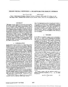
Computed Tomography (CT) is the third generation of measuring techniques used in the field of dimensional metrology. Its main advantages in contrast to tactile or optical measurements rely in short scanning time, possibility to measure internal features and high information density. Due to a large number of influence quantities occurring in the whole CT process, and the fact that CT systems are multi-purpose measuring devices, measuring uncertainties are in many cases unknown. This is also because standards and procedures are still under development [1]. The attempt is to develop reference objects, similar to objects used in classical coordinate metrology, for the identification of error sources and their correction. This work presents a new reference object, a “CT ball plate” (Figure 1 left), used for performance assessment of CT systems, its calibration using a coordinate measuring machine (CMM) and the first tests using a CT system. This object enables to measure probing errors and length measuring errors in accordance to procedures applied in classical coordinate metrology.
Proceedings of the 12th euspen International Conference – Stockholm – June 2012
2
Design and calibration
The CT ball plate features a regular 5 x 5 array of ruby spheres with a nominal diameter of 5 mm. The balls are glued on a carbon fibre plate using a two-component epoxy resin, ensuring long-term stability of the position of the balls. Carbon fibre is a material widely used in CT scanning applications due to its high penetrability rate to X-rays. The concept of the CT ball plate is similar to the calotte plate developed by Physikalisch-Technische Bundesanstalt (PTB) [2]. In our case, the ruby balls feature well defined geometries compared to the calottes on the calotte plate, and therefore minimize manufacturing inaccuracies. The calibration of the artefact was carried out using a Zeiss OMC 850 tactile CMM at the laboratory of the Technical University of Denmark (DTU). The calibration procedure combines the use of the reversal method and the guidelines for the application of DIN EN ISO 10360. The traceability was transferred by measuring a calibrated ball plate commonly used for calibration of CMMs (Figure 1 right). Calibration was repeated three times in two positions (D0 and D180) defined by turning the part by 180 degrees, and reproduced in three different days. The CT ball plate was re-positioned in the fixture when measured in different days. Measuring uncertainties were calculated for four selected measurands: diameter of spheres and X-, Y- and Z-coordinates of sphere centers. Three uncertainty contributors were taken into account in the uncertainty budgeting: Uncertainty from the calibration certificate of the ball plate Uncertainty during to the traceability transfer Uncertainty from measurement repeatability (D0+D180). Measuring uncertainties were assessed as maximum expanded uncertainties at 95% confidence level for each measurand, taking into account all 25 balls, calculated in different days, and are summarized in Table 1. The calculated uncertainties yield high measuring reproducibility with complete comparability of measuring results obtained in the different days.
Table1: Expanded uncertainties for calibration of the CT ball plate.
U (k=2) [µm]
Diameter
X-coord.
Y-coord.
Z-coord.
0.9
2.2
1.7
4.0
Proceedings of the 12th euspen International Conference – Stockholm – June 2012
Figure 1: CT ball plate (left) and a setup for traceability transfer using a ball plate as part of the calibration procedure of the CT ball plate using CMM (right).
3
First test on µCT systems
The CT ball plate was scanned using a Nikon Metrology XT H 225 ST CT scanner at PTB Braunschweig (Figure 2 left). The test procedure involves measurement of center coordinates of spheres, their diameter and form error, similarly to the procedures applied to CMMs. This allows the determination of length measuring errors, sphere distance errors and probing errors. The reference object was scanned according to VDI/VDE 2630 – Part 1.3 [3]. This guideline suggests scanning an object at two different magnifications and orientations. In this way, spatial distribution of errors can be determined. In addition, the test method involves correction of scale errors in all space directions. Errors found for different positions and orientations of the object in the CT volume are a result of anisotropies in the measuring volume of the CT system. Figure 2 (right) shows four positions of the object in the CT volume considered in this study. Figure 3 presents results of length measuring errors which occurred at positions 1 and 3. The results were corrected for scale errors applying linear regression function. A clear difference in the magnitude of the errors can be observed between the two positions. This is caused by the fact that the object is scanned at the borders of the Xray detector (position 3) where errors due to Feldkamp effect are pronounced [1].
Figure 2. Scanning of the CT ball plate using Nikon Metrology CT scanner (left) and four positions of the CT ball plate in the CT volume in side view (right).
Proceedings of the 12th euspen International Conference – Stockholm – June 2012 20
Sphere distance error [µm]
Sphere distance error [µm]
20 15 10 5 0 -5 -10 -15 -20
15 10 5 0 -5 -10 -15 -20
0
10
20
30
40
50
60
0
10
Calibrated length [mm]
20
30
40
50
60
Calibrated length [mm]
Figure 3: Sphere distance error at position 1 (left) and position 3 (right) for scanning of the CT ball plate using Nikon Metrology CT scanner.
5
Conclusion and outlook
The new reference object – CT ball plate – appears to be a useful tool for performance testing of CT systems. The object will be further applied in connection with quantification of measuring errors in the CT volume.
Acknowledgements The authors would like to thank Mr. Markus Bartscher and Mr. Ulrich NeuschaeferRube from PTB (Braunschweig, Germany) in connection with preparation and CT scanning of the object. Thanks belong to Mr. Jakob Rasmussen for help in connection with CMM measurements.
References: [1] Kruth, J.P., Bartscher, M., Carmignato, S., Schmitt, R., De Chiffre, L. and Weckenmann, A. (2011). Computed Tomography for Dimensional Metrology, keynote paper, CIRP Annals, 61/2, 821-842. [2] Bartscher, M., Hilpert, U., Goebbels, J., Weidemann, G. (2007). Enhancement and Proof of Accuracy of Industrial Computed Tomography (CT) Measurements, CIRP Annals, 56/1, 495-498. [3] VDI/VDE 2630 - Part 1.3 Computed tomography in dimensional measurement, Guideline for the application of DIN EN ISO 10360 for coordinate measuring machines with CT sensors, 12/2011.


![Comaprison paper [postprint] - DTU Orbit](https://m.moam.info/img/260x300/comaprison-paper-postprint-dtu-orbit_5991f25a1723ddcf69a3fc3f.jpg)

![Comaprison paper [postprint] - DTU Orbit](https://m.moam.info/img/260x300/comaprison-paper-postprint-dtu-orbit_5c15086c097c4766398b46d5.jpg)