I would also like to thank Juan F. Monge for the generous research collaboration ...... P. Beraldi, L. Grandinetti, R. Musmanno, and C. Trik. Parallel algorithms to.
On parallel omputing for sto hasti optimization models and algorithms Unai Aldasoro Mar ellan
Supervisors: Gloria Pérez Sainz de Rozas and María Merino Maestre
Leioa, 2014
Fa ultad de Cien ia y Te nología Departamento de Matemáti a Apli ada y Estadísti a e Investiga ión Operativa
Servicio Editorial de la Universidad del País Vasco (UPV/EHU) Euskal Herriko Unibertsitateko Argitalpen Zerbitzua (UPV/EHU) University of the Basque Country - Editorial Service (UPV/EHU) ISBN: 978-84-9082-055-1
gure osaba Iñigo eta Enriqueri to my uncles Iñigo and Enrique
Eguzkiak urtzen du goian gailurretako elurra, uharka da jausten ibarrera geldigaitza den oldarra.
High on the peaks the sun melts the snow gushing down to the valley an unstoppable force.
J. Artze & M. Laboa, Martxa baten lehen notak, First chords of a march
Acknowledgments First and foremost I wish to thank my supervisors Gloria and María. Your dynamism, energy and reflexive attitude have been the greatest pleasure of this thesis. Without your critical view and support this research would have not been possible. I offer my gratitude to Professor Laureano F. Escudero for the encouragement, insightful comments and all his advice. I would also like to thank Juan F. Monge for the generous research collaboration and Araceli Garín, Larraitz Aranburu and Aitziber Unzueta from the Grupo de Optimización Estocástica (GOE) research group for their warm welcome. My sincerest thanks are owed to Professor Jacek Gondzio for the opportunity to work in the University of Edinburgh as visiting Ph.D. student and share research with the Edinburgh Research Group in Optimization (ERGO). I would like to acknowledge the financial, academic and technical support of the University of the Basque Country, the Basque Government by the IT-567-13 project and also to the Ministry of Economy and Competitiveness by the MTM2012-31514 project that have partially financed my participations in conferences. The scientific computing service, SGI/IZO-SGIker from UPV/EHU, has been indispensable, specially the magnificent support by Txema Mercero and Edu Ogando. I also thank the departments of Matemática Aplicada y Estadística e Investigación Operativa, for providing me with the necessary material for my research, Máquinas y Motores Térmicos and Matemática Aplicada for the excellent atmosphere during the time I spent with them.
Lagunei, beti hor egoteagatik eta bide luze hau egiten laguntzeagatik. Suziritarrak, albokalariak, interrailekoak, Toulousedarrak, zeharlanekoak, Garrotxakoak, Amara Zaharreko lagun zaharrak, Imanol, mila esker. A mi familia, por el esfuerzo de tantos años para que me pueda dedicar a lo que más me gusta; este trabajo es vuestro. Gure aiton-amonei, irakatsi didazuen guztiagatik, amari eta aitari, naizena zor dizuet. Esker mila gure arreba Iratiri, alaitasun eta bizi-poza. Nire azken irrifarra Nahiarentzat, uneoro alboan izateagatik, dena errazago egiteagatik.
Contents Contents
i
List of Figures
v
List of Tables
vii
List of Algorithms
viii
1 Introduction 1.1 Aims of the work . . . . . . . . . . . . . . . . . . . 1.2 Overview and contributions . . . . . . . . . . . . . 1.3 Basic concepts of Parallel Computing . . . . . . . . 1.4 A brief state-of-the-art on Parallel Computing . . . 1.5 Computing resources . . . . . . . . . . . . . . . . . 1.6 A brief state-of-the-art on Stochastic Optimization 1.7 Multistage stochastic mixed 0-1 optimization . . . 2 Parallel computing in optimization 2.1 Introduction . . . . . . . . . . . . . . . . . . . . . 2.2 Message-passing parallelization . . . . . . . . . . 2.3 Parallel computing to solve multiple optimization 2.3.1 Preliminary computational testing . . . . 2.3.2 Computational experience . . . . . . . . . 2.4 Inner parallelization paradigm . . . . . . . . . . . 2.5 Multipath Branch & Bound Algorithm . . . . . . 2.5.1 Simultaneous branching . . . . . . . . . . 2.5.2 Stage perspective . . . . . . . . . . . . . . 2.6 Outer parallelization paradigm . . . . . . . . . . i
. . . . . . .
. . . . . . .
. . . . . . .
. . . . . . .
. . . . . . .
. . . . . . .
1 1 2 3 5 7 8 10
. . . . . . . . . . . . problems . . . . . . . . . . . . . . . . . . . . . . . . . . . . . . . . . . . . . . . . . .
. . . . . . . . . .
. . . . . . . . . .
. . . . . . . . . .
. . . . . . . . . .
. . . . . . . . . .
15 15 16 18 21 22 26 26 27 35 36
. . . . . . .
. . . . . . .
. . . . . . .
. . . . . . .
Contents 2.7
Conclusions . . . . . . . . . . . . . . . . . . . . . . . . . . . . . . . .
37
3 Parallel Branch-and-Fix Coordination 3.1 Introduction . . . . . . . . . . . . . . . . . . . . . . . . . . . . . . 3.2 Break stage scenario clustering . . . . . . . . . . . . . . . . . . . 3.3 BFC decomposition algorithm . . . . . . . . . . . . . . . . . . . . 3.3.1 Basic definitions and auxiliary models . . . . . . . . . . . 3.3.2 Procedure . . . . . . . . . . . . . . . . . . . . . . . . . . . 3.4 Inner parallelization of the BFC algorithm . . . . . . . . . . . . . 3.5 Outer parallelization of the BFC algorithm . . . . . . . . . . . . 3.6 Outer-Inner parallelization of the BFC algorithm . . . . . . . . . 3.7 Computational experience . . . . . . . . . . . . . . . . . . . . . . 3.7.1 Testbed dimensions . . . . . . . . . . . . . . . . . . . . . 3.7.2 Scenario clustering solution value and related GAPs . . . 3.7.3 Preliminary analysis: Parallel solving of root node . . . . 3.7.4 Inner P-BFC strategies versus plain use of CPLEX . . . . 3.7.5 Outer P-BFC strategies versus plain use of CPLEX . . . 3.7.6 Outer-Inner P-BFC strategies versus plain use of CPLEX 3.8 Conclusions . . . . . . . . . . . . . . . . . . . . . . . . . . . . . .
. . . . . . . . . . . . . . . .
. . . . . . . . . . . . . . . .
39 39 40 44 44 47 50 54 60 62 62 62 64 66 68 71 73
4 Parallel Stochastic Dynamic Programming 4.1 Introduction . . . . . . . . . . . . . . . . . . . . . . . . . . . . . . 4.2 SDP decomposition algorithm . . . . . . . . . . . . . . . . . . . . 4.2.1 Breaking the time horizon into stages . . . . . . . . . . . 4.2.2 SDP decomposition algorithm . . . . . . . . . . . . . . . . 4.2.3 λ(·) curves approximation . . . . . . . . . . . . . . . . . . 4.3 On parallelizing the SDP decomposition algorithm . . . . . . . . 4.3.1 P-SDP parallelization strategies . . . . . . . . . . . . . . . 4.3.2 Inner P-SDP parallelization strategy . . . . . . . . . . . . 4.3.3 Outer P-SDP parallelization strategy . . . . . . . . . . . . 4.4 Computational experience . . . . . . . . . . . . . . . . . . . . . . 4.4.1 Serial implementation overview . . . . . . . . . . . . . . . 4.4.2 Inner parallel implementation overview . . . . . . . . . . 4.4.3 Outer parallel implementation overview . . . . . . . . . . 4.4.4 Testbed problem: Production planning under uncertainty 4.4.5 Testbed dimensions . . . . . . . . . . . . . . . . . . . . . 4.4.6 Serial SDP and parallel SDP . . . . . . . . . . . . . . . . 4.5 Conclusions . . . . . . . . . . . . . . . . . . . . . . . . . . . . . .
. . . . . . . . . . . . . . . . .
75 . 75 . 76 . 76 . 79 . 81 . 82 . 82 . 82 . 86 . 87 . 87 . 89 . 89 . 92 . 94 . 96 . 105
5 Perspectives on solving large-scale problems 107 5.1 Introduction . . . . . . . . . . . . . . . . . . . . . . . . . . . . . . . . 107 5.2 D-BFC decomposition algorithm . . . . . . . . . . . . . . . . . . . . 108 ii
Contents
5.3 5.4 5.5
5.6 5.7
5.2.1 Stage-wise model ordering . . . . . . . . . . . . . . . . . . . 5.2.2 Dynamic node branching . . . . . . . . . . . . . . . . . . . H-BFCs, D-BFC based matheuristic algorithms . . . . . . . . . . . D-BFC and H-BFC procedures . . . . . . . . . . . . . . . . . . . . 5.4.1 Solving performance example of BFC, D-BFC and H-BFCs Computational experience . . . . . . . . . . . . . . . . . . . . . . . 5.5.1 D-BFC compared to BFC in medium-scale problems . . . . 5.5.2 H-BFCs compared to SDP in large-scale problems . . . . . Perspectives on parallelizing the H-BFC decomposition algorithm . Conclusions . . . . . . . . . . . . . . . . . . . . . . . . . . . . . . .
. . . . . . . . . .
108 109 112 114 116 119 120 121 122 124
6 Conclusions and future research 127 6.1 Conclusions . . . . . . . . . . . . . . . . . . . . . . . . . . . . . . . . 127 6.2 Future research . . . . . . . . . . . . . . . . . . . . . . . . . . . . . . 131 A Message Passing Interface syntax A.1 Declaring MPI variables . . . . . A.2 Beginning of a MPI environment A.3 Identifying and grouping threads A.4 Communication functions . . . . A.5 Finishing the MPI environment . A.6 Example code . . . . . . . . . . .
. . . . . .
. . . . . .
. . . . . .
. . . . . .
. . . . . .
. . . . . .
. . . . . .
. . . . . .
. . . . . .
. . . . . .
. . . . . .
. . . . . .
. . . . . .
. . . . . .
. . . . . .
. . . . . .
. . . . . .
. . . . . .
. . . . . .
. . . . . .
133 133 134 134 135 138 138
B P-BFC programming codes
141
C P-SDP programming codes
143
D Predoctoral training and visibility
147
Glossary
151
Nomenclature
153
Acronyms
159
Bibliography
161
iii
List of Figures 1.1 1.2
Parallel architectures . . . . . . . . . . . . . . . . . . . . . . . . . . . . . An example of scenario tree . . . . . . . . . . . . . . . . . . . . . . . . .
6 11
2.1 2.2 2.3 2.4 2.5 2.6 2.7 2.8 2.9 2.10
General structure of a MPI implementation . . . . . . . . . . . . Serial execution. Basic steps. . . . . . . . . . . . . . . . . . . . . MPI based parallel execution. Basic steps. . . . . . . . . . . . . . Parallelization diagram (1 main × 2 task × 4 auxiliary) threads Classification for (task × auxiliary) threads execution time . . . Speedup and efficiency vs number of threads . . . . . . . . . . . Multipath Branch & Bound algorithm. Basic steps . . . . . . . . Knapsack problem example. One-path B&B . . . . . . . . . . . . Knapsack problem example. Two-path B&B . . . . . . . . . . . . Knapsack problem example. Four-path B&B . . . . . . . . . . .
. . . . . . . . . .
. . . . . . . . . .
. . . . . . . . . .
. . . . . . . . . .
17 18 19 20 25 26 30 31 33 34
3.1 3.2 3.3 3.4 3.5 3.6 3.7
Scenario clustering for t∗ = 0, t∗ = 1 and t∗ = 2 . . . . . . . . . . Parallel computing strategies: task threads with auxiliary threads Illustrative one-path (1 × 2 × 4) Inner P-BFC diagram . . . . . . Illustrative four-path (4 × 1 × 1) Outer P-BFC diagram . . . . . . Two-path Outer P-BFC performance for instance P3 . . . . . . . . Scalability of instance P3. Outer P-BFC versus Inner P-BFC . . . Elapsed time comparison for P-BFC, serial BFC and CPLEX . . .
. . . . . . .
. . . . . . .
. . . . . . .
42 50 52 56 58 70 73
4.1 4.2 4.3 4.4 4.5 4.6
An example of multiperiod scenario tree . . . . . . . . . . . . An example of λℓ (·) curve and its approximation EFV . . . . Inner parallelization scheme with 8 task threads . . . . . . . Outer P-SDP scheme for simultaneous execution of p paths . Detail of communication and synchronization phase for Outer Scalability of instances c85 and c86 . . . . . . . . . . . . . . . v
. . . . . . . . . . . . . . . . . . . . P-SDP . . . . .
. 78 . 79 . 85 . 88 . 88 . 104
List of Figures 5.1 5.2 5.3 5.4 5.5 5.6 5.7
Group-wise model ordering example . . . . . . . . . . . . . . . . . Stage-wise model ordering example . . . . . . . . . . . . . . . . . . BFC performance for instance P3 . . . . . . . . . . . . . . . . . . . D-BFC and H1-BFC performance for instance P3 . . . . . . . . . . H2-BFC performance for instance P3 . . . . . . . . . . . . . . . . . H3-BFC performance for instance P3 . . . . . . . . . . . . . . . . . Outer-Inner PH-BFC with dynamic four-path assignment example
vi
. . . . . . .
. . . . . . .
. . . . . . .
109 109 117 118 119 119 124
List of Tables 1.1
Computational experience ARINA nodes
. . . . . . . . . . . . . . . . .
7
2.1 2.2 2.3 2.4 2.5 2.6 2.7 2.8 2.9 2.10 2.11 2.12
Preliminary test. COIN-OR. 9 instances. . . . . . . . . . . . . . . . . . Medium-scale problem dimensions . . . . . . . . . . . . . . . . . . . . . Subproblem average (standard deviation) dimensions. . . . . . . . . . . Solution values for the 44 subproblems. Testbed 1. . . . . . . . . . . . . Computing times under COIN-OR. Testbed 1. . . . . . . . . . . . . . . Computing times under CPLEX (single auxiliary thread). Testbed 1. . Computing times under CPLEX (multiple auxiliary threads). Testbed 1. Efficiency of COIN-OR and CPLEX. Testbed 1. . . . . . . . . . . . . . One-path solving process. Solutions . . . . . . . . . . . . . . . . . . . . Two-path solving process. Solutions . . . . . . . . . . . . . . . . . . . . Four-path solving process. Solutions . . . . . . . . . . . . . . . . . . . . Effect of the variable order and the fixing criterion . . . . . . . . . . . .
21 23 23 23 24 24 25 26 31 32 34 36
3.1 3.2 3.3 3.4 3.5 3.6 3.7 3.8 3.9 3.10 3.11 3.12 3.13
Two-path Outer P-BFC performance for instance P3 . . . . . . . . . Dimensions of DEM, compact representation. Testbed 2. . . . . . . Stochastic solution values and GAPs. Testbed 2. . . . . . . . . . . . Elapsed time for solving the root node of instances P1-P4 . . . . . . Elapsed time for solving the root node of instances P5-P9 . . . . . . Elapsed time for solving the root node of instances P10-P14 . . . . . Elapsed time for solving the root node in Testbed 2. Summary for t∗ Elapsed time for solving the root node in Testbed 2. Summary for t∗ Inner P-BFC for t∗ = 1 versus plain use of CPLEX. Testbed 2. . . . Inner and Outer P-BFC scalability for t∗ = 1 in P3 and P4 . . . . . Outer P-BFC for t∗ = 1 versus plain use of CPLEX. Testbed 2. . . . Outer-Inner P-BFC versus plain use of CPLEX. Testbed 2. . . . . . Best P-BFC strategies summary. Testbed 2. . . . . . . . . . . . . . .
59 63 63 65 66 67 67 68 68 69 70 71 72
vii
. . . . . . . . . . . . =1 =2 . . . . . . . . . .
List of Tables 4.1 4.2 4.3 4.4 4.5 4.6 4.7 4.8 4.9 4.10
Problem dimensions. Testbed 3 . . . . . . . . . . . . . . . . . . . . . Smallest and largest subproblem dimensions. Testbed 3 . . . . . . . Plain use of CPLEX. Solution value and elapsed time. Testbed 3 . . SDP and Inner P-SDP. Solution value and elapsed time. Testbed 3 . Problem dimensions. Testbed 4 . . . . . . . . . . . . . . . . . . . . . Smallest and largest subproblem dimensions. Testbed 4 . . . . . . . Plain use of CPLEX. Solution value and elapsed time. Testbed 4 . . SDP and Inner P-SDP. Solution value and elapsed time. Testbed 4 . SDP and Outer P-SDP. Comparing solution value and elapsed time Inner P-SDP scalability for instances c85 and c86 . . . . . . . . . . .
. . . . . . . . . .
. . . . . . . . . .
95 96 97 98 99 100 101 102 103 104
5.1 5.2 5.3 5.4 5.5 5.6 5.7
BFC variable branching performance, example . D-BFC variable branching performance, example D-BFC and H-BFC algorithms . . . . . . . . . . Effect of model ordering in elapsed time. Testbed D-BFC performance. Testbed 2. . . . . . . . . . H-BFC performance. Testbed 2 . . . . . . . . . . H-BFC performance. Testbed 3 . . . . . . . . . .
. . . . . . .
. . . . . . .
112 112 113 120 121 122 122
. . . . . . 2. . . . . . .
. . . . . . .
. . . . . . .
. . . . . . .
. . . . . . .
. . . . . . .
. . . . . . .
. . . . . . .
. . . . . . .
. . . . . . .
A.1 Operation options of the Reduce function . . . . . . . . . . . . . . . . . 137
viii
List of Algorithms 2.1
Multipath Branch & Bound . . . . . . . . . . . . . . . . . . . . . . . .
29
3.1
Serial BFC . . . . . . . . . . . . . . . . . . . . . . . . . . . . . . . . .
49
3.2
Inner P-BFC . . . . . . . . . . . . . . . . . . . . . . . . . . . . . . . .
53
3.3
Outer P-BFC . . . . . . . . . . . . . . . . . . . . . . . . . . . . . . . .
55
3.4
Outer-Inner P-BFC . . . . . . . . . . . . . . . . . . . . . . . . . . . .
61
4.1
Serial SDP . . . . . . . . . . . . . . . . . . . . . . . . . . . . . . . . .
83
4.2
Inner P-SDP . . . . . . . . . . . . . . . . . . . . . . . . . . . . . . . .
90
4.3
Outer P-SDP . . . . . . . . . . . . . . . . . . . . . . . . . . . . . . . .
91
5.1
Model ordering . . . . . . . . . . . . . . . . . . . . . . . . . . . . . . . 110
5.2
Serial D-BFC and H-BFCs . . . . . . . . . . . . . . . . . . . . . . . . 115
5.3
Dynamic path assignment Outer-Inner PH-BFC . . . . . . . . . . . . 125
ix
Chapter
Introduction Machines take me by surprise with great frequency. Alan Turing
1.1
Aims of the work
This thesis aims to connect Stochastic Optimization (SO) and Parallel Computing (PC) in order to solve large scale optimization problems under uncertainty. The proposed approach links mathematical perspective, by developing decomposition algorithms, and a computer science environment, by using parallel computing resources and implementations. Depending on the chosen objective, this connection allows problems to be solved faster, larger problems to be solved or/and better results to be obtained. A new paradigm for developing decomposition algorithms is therefore proposed. Therefore, the proposal in this memoir not only executes serial algorithm steps in parallel, but more interestingly also adapts and extends serial algorithms to be computationally more efficient in a parallel computing environment. This is achieved by allowing deeper decomposition of the original problem, by sharing the feasibility area, by creating synchronization and communication phases among parallel executions or by defining divergent initial conditions. Consequently, parallel computing approaches are presented for exact algorithms as well as for matheuristic ones (the interoperation of metaheuristic methodologies and Mathematical Programming). The scalability and performance of each implementation are analysed using four problem testbeds of different scales: small, medium, large and very large, respectively. Around 150 problems have been tested, where the largest problem has 53.9 million variables (15.4 million of which are binary 1
1
Chapter 1
Introduction
ones) and 57.8 million constraints. Finally, this research aims to contribute to the discipline related to parallel computing-conceived optimization algorithms where important domains of Mathematical Optimization could interact with a parallel computing environment, i.e., multiple aspects of the problem are exploited in parallel such as cuts, decomposition, heuristic search and so on.
1.2
Overview and contributions
The basic concepts of Parallel Computing and Stochastic Optimization are presented in this chapter. This memoir introduces the path concept that links mathematical algorithms with parallel computing executions, allowing more complex parallel environments to be defined in terms of designing dynamic algorithms, building hybrid algorithms or searching for multiple simultaneous objectives. Additionally, a state-of-the-art description of parallel computing algorithms being designed and implemented to solve stochastic mixed 0-1 multistage problems is included. Chapter 2 considers the main ideas of Parallel Computing applied to Stochastic Optimization from two perspectives: solving several small-scale subproblems of largescale models in parallel, leading to the so-named inner parallelization being defined, and solving a single mixed 0-1 problem by parallel branching, creating a so-named outer parallelization environment. These paradigms are applied in the next chapters to decomposition algorithms due to their flexibility in terms of possible model and task division, obtaining a remarkable speed-up and efficiency, see Aldasoro et al. [2012]. Chapter 3 presents three exact Parallel Branch-and-Fix Coordination (P-BFC) algorithms: Inner P-BFC (that reproduces the serial steps and performs tasks in parallel, when possible), Outer P-BFC (based on simultaneous execution of paths) and a combined Outer-Inner P-BFC as an innovative approach to solve medium-scale mixed 0-1 optimization problems by parallel branching and simultaneous subproblem solving. The proposed approaches obtain the optimal solution significantly faster than the serial BFC and solve problems that the state-of-the-art optimization engine cannot prove optimality, see Aldasoro et al. [2013a]. Chapter 4 introduces a version of the matheuristic decomposition algorithm Stochastic Dynamic Programming, that allows large and very large-scale stochastic problems to be solved. This research also contributes to parallel computing to obtain tight bounds in very large-scale problems where the state-of-the-art optimization engine cannot prove optimality, and for the largest instances, where that engine cannot obtain any feasible solution. To do so, a Parallel Stochastic Dynamic 2
1.3
Basic concepts of Parallel Computing
Programming (P-SDP) approach is proposed in two paradigms: Inner P-SDP and Outer P-SDP. A production planning problem has been used as a testbed for the broad computational experience that is reported in the chapter, showing that the ad-hoc P-SDP implementations enable not only a faster solution to be obtained but also a tighter bound than the serial SDP, see Aldasoro et al. [2014]. Chapter 5 presents some perspectives on solving large-scale problems. The chapter shows that the deeper algorithmic understanding resulting from a parallel implementation leads to an improvement of the serial algorithm. Thus, the sonamed Dynamically guided and stage ordered Branch-and-Fix-Coordination (DBFC) improves the use of the stochastic tree structure. Additionally, several matheuristic versions of the D-BFC algorithm are presented, based on the relaxation of some steps of the exact algorithm, in order to solve very large-scale problems. See Aldasoro et al. [2013b] for a detailed description of the model ordering improvements Finally, Chapter 6 summarizes the conclusions drawn from this research and outlines future research lines regarding the parallel computing approach of decomposition algorithms, such as massively decomposition algorithms solved by Graphic Processing Units (GPUs), data decomposition, simultaneous risk averse analysis and, in general, new perspectives on designing algorithms.
1.3
Basic concepts of Parallel Computing
Let us define several basic concepts of parallel computing:
• A computer cluster consists of multiple computers with software that allows the group to be viewed as a single system. • A computing node is a single computer system (motherboard, one or more processors, memory, network interface) within a cluster. • A Central Processing Unit (CPU), commonly referred to as the processor, is the piece of hardware within a computing node that carries out the instructions of a computer program, such as the basic arithmetical, logical, and input/output operations. A computer (or computing node) can have more than one processor (CPU). • A core is a physical processing unit within a CPU chip that reads and executes program instructions. Currently multi-core processors (CPUs) are widely used. Core-to-core communication is significantly faster than processor-to-processor communication. 3
Chapter 1
Introduction
• A thread is a single line of commands that is active in a core. Generally, a processor can only work on one thread per core. However, state-of-the art processors allow multithreading inside a core, i.e., core level parallelization.
Therefore, a thread is the most elemental processing unit and is used throughout the work to denote an independent line of commands execution. In parallel computing the modeler can assign different tasks to the available threads, define a hierarchy, create thread groups or subgroups and assign communication environments. Let us present the naming convention used in this research regarding the programmer defined thread management:
The thread-algorithm link is considered as follows: • A path is an independent execution of an algorithm under a given set of initial conditions. In a multiple path execution environment, the behaviour of a path may change depending on the results obtained by other paths. A serial algorithm execution can be considered as one-path. The thread hierarchy is as follows: • A main thread executes a copy of the implemented program and it is in charge of managing a path. The set of main threads is called the main thread group, with its cardinality being equal to the number of paths. The main thread performs the non-parallelized steps of an algorithm execution. • A task thread executes a copy of the implemented problem and it is assigned to perform the parallelizable tasks of a path. Note that main threads are also task threads. A task thread group is composed of a main thread and its associated additional task threads. • Any thread that works on a subproblem solving process is an auxiliary thread. In addition to main thread and tasks threads (which are also auxiliary threads), the state-of-the-art optimization engine of choice may use additional auxiliary threads for its internal parallelization. Therefore, an auxiliary thread group is composed of a main thread, a set of task threads and the auxiliary threads associated to each task thread. The solver-driven auxiliary threads are not linked to a copy of the implemented program and, therefore, are not directly controlled by the user. • The thread assignation of a parallel environment is denoted as (a × b × h), where a is the number of main threads (one for each path), b is the number 4
1.4
A brief state-of-the-art on Parallel Computing
of task threads associated to each main thread (including itself) and h is the number of auxiliary threads associated to each task thread (including itself). Additionally, task threads can be divided into subgroups: • A task thread subgroup is a subgroup of task threads within a task group. • A coordinator task thread is a task thread that manages a task thread subgroup and leads the communication. • A subordinated task thread is a task thread inside a task thread subgroup that performs the steps required by the corresponding coordinator task thread. Four communication environments can be considered: • The global communication environment allows the information exchange among all threads that execute a copy of the program, i.e., main threads and task threads. • The primary communication environment allows the information exchange within the main group. • The secondary communication environment allows the information exchange within a task group, i.e., among a main thread and its associated task threads. • The tertiary communication environment allows the information exchange within a task thread subgroup. The execution coordination can be performed in two ways: • A synchronized execution implies that all task thread groups are always at the same algorithmic point. • An asynchronized execution implies that all task thread groups are not necessarily always at the same algorithmic point, i.e., the executions of different groups may diverge.
1.4
A brief state-of-the-art on Parallel Computing
Parallel Computing is a computer science area that studies the necessary hardware and software aspects to perform simultaneous execution of tasks. Currently, this discipline is the prominent paradigm in high performance computing and also in computer architecture, due to the industry’s shift to multicore processors at hardware level. That type of platform embraces architecture, algorithms 5
Chapter 1
Introduction
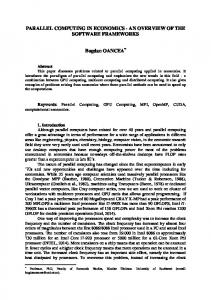
and methods that brings an otherwise unreachable computing power under the programmer’s control. At the hardware level, the parallel computing era started in the late 1950s in the form of shared memory multiprocessor supercomputers. The development of this type of computers continued until the early 1980s when a new paradigm of massively parallel multiprocessors (MPPs) arrived. MPPs wee seen to perform significantly better and became dominant in high performance computing. In the late 1980s computing clustering technology emerged when a large numbers of offthe-shelf computers connected by an off-the-shelf network were linked. Nowadays, parallel computing is mainly based on clusters and multicore processors. Every six months, the Top 500 website gathers the information on the best supercomputing sites globally http://www.top500.org/. For more in-depth information on parallel computing hardware, see Culler et al. [1997]; Hennessy and Patterson [2003], among others. The cooperation among processors differ depending on the way processors exchange information. The basic parallel architectures correspond to shared memory and distributed memory (managed by message-passing). As described in Linderoth [1998] “one processor of a shared memory machine can communicate with another by writing the information into a global shared memory location and having the second processor read directly from that location” using a bus. So, communication is carried out by shared variables. This makes inter-processor communication very easy and fast, but it has the drawback of simultaneous access to a unique memory location. On the other hand, each processor on the distributed memory paradigm has its own local memory connected by a network with the others, so, the communication is based on message-passing.
P
P
P
P
bus
P
P
P
P
M
M
M
M
general network
M shared memory
distributed memory
Figure 1.1: Parallel architectures (P: processor, M: memory) Regarding mathematical optimization, we often find large-scale problems or we need to solve many of them, which cannot be performed efficiently by a single processor, even if computer science technology is constantly improving. Parallel 6
1.5
Computing resources
Computing is a powerful tool to manage this type of problems, and operate on the principle that large problems can often be divided into smaller ones. The idea is simple: to use p processors in cooperation in order to (ideally) be able to solve a problem p times faster or to solve a p times larger problem using the same amount of computing time.
1.5
Computing resources
The computing experiments in this research were conducted at the ARINA computational cluster at SGI/IZO-SGIker from Universidad del País Vasco/Euskal Herriko Unibertsitatea, UPV/EHU. During the research for this thesis ARINA provided 147 nodes connected by an QDR infiniband network with high bandwidth (maximum rate of successful messages delivered over a communication channel) and low latency (time interval between signal and response) and a 22 Tb high performance Lustre based file system for data storage. The 147 nodes and 1400 cores were divided as follows: 147 Intel Xeon processor nodes (1112 cores in overall), 30 Intel Itanium processor nodes (248 cores in overall) and 5 AMD Opteron processor nodes (40 cores in overall). Table 1.1 summarizes the characteristics of the ARINA nodes used for the computational experience considered here. The headings are as follows: T ype, processor brand in the computing node; P roc., number of processors per computing node; Core, number of cores per computing node; F requency, CPU clock rate; RAM , Random-access memory; Disc, hard disk data storage capacity; max.use, maximum resources of that type used in a single execution, where N indicates number of nodes and C number of cores; and finally Ch. indicates the chapters of the thesis in which each resources are used. Table 1.1: Computational experience ARINA nodes Type Intel Xeon Intel Xeon
Proc. 2 2
Cores 8 12
Frequency 2.3 GHz 2.4 GHz
RAM 48 Gb 48 Gb
Disc 250 Gb 250 Gb
max. use 16N, 128C 8N, 96C
Ch. 2-3-5 4
The algorithms in Chapter 2, Chapter 3 and Chapter 5 are implemented in a C++ experimental code, whereas they are implemented in a C experimental code in Chapter 4. The state-of-the-art LP/MIP solver CPLEX (versions V12.2 and V12.5) called from the open source library COIN-OR (versions V1.3.1 and V1.6.0) is used as optimization engine. The IntelMPI library is used as the Message Passing Interface (MPI) standard for the message-passing communication in parallel environment. 7
Chapter 1
1.6
Introduction
A brief state-of-the-art on Stochastic Optimization
Stochastic Optimization (SO) is actually one of the most reliable tools for decisionmaking. Since the 1950s, it has been well known that traditional deterministic optimization is not appropriate for capturing the uncertain behaviour present in most real world applications. Beale [1955] and Dantzig [1955] began to study optimization problems under uncertainty, followed by Charnes and Cooper [1959] and others, see also Wets [1974, 1975]. Moreover, it was not until the 1980s when Stochastic Optimization was broadly applied in real-world applications. Uncertainty is the key ingredient in many decision problems. There are several ways in which uncertainty can be formalized and different approaches to optimization under uncertainty have been developed over the past thirty years. The field of SO appears as a response to the need of uncertainty to be incorporated in mathematical optimization models. Basically, it deals with situations in which some parameters are random variables. It allows the management, partially at least, of the risk inherent to the random variables of the problem mainly in a time horizon environment. New problem formulations appear almost every year and this variety is one of the strengths of the field. Very frequently, mainly in problems with a given time horizon to exploit, some coefficients in the objective function, the right hand side (rhs) vector and the constraint matrix are not known with certainty when the decisions have to be made, but some information is available. This circumstance allows to use Stochastic Integer Optimization (SIO) to solve multistage mixed 0-1 problems under uncertainty. The problem is formulated by the so-named Deterministic Equivalent Model (DEM), a term coined by Wets [1974], that was first solved by using Benders Decomposition (BD), see Benders [1962]; van Slike and Wets [1969]; Birge and Louveaux [2011]; Laporte and Louveaux [2002], among others. A generalization of BD is given in Carøe and Tind [1998] to deal with two-stage stochastic programs having 0-1 mixed-integer recourse variables and either pure continuous or pure first-stage 0-1 variables. A decomposition algorithm based on a branch-and-cut approach to solve two-stage stochastic programs having firststage pure 0-1 variables and 0-1 mixed-integer recourse variables is proposed in Sen and Sherali [2006], where a modified BD method is developed. Branch-andbound algorithms for problem solving having mixed-integer variables in both stages are presented in Carøe and Schultz [1999]; Hemmecke and Schultz [2001]. A general algorithm to solve two-stage stochastic mixed 0-1 problems is presented in Escudero et al. [2007, 2009b, 2010a]. In the general formulation of a multistage stochastic integer optimization problem, decisions in each stage have to be made stage-wise. At each stage, there are variables which correspond to decisions that have to be made without anticipation of some of future problem data, i.e., 8
1.6
A brief state-of-the-art on Stochastic Optimization
they take the same value under each scenario in a given group (then, the sonamed non-anticipativity constraints (NAC) must be satisfied, stated in Wets [1975] and restated in Rockafellar and Wets [1991], see also Birge and Louveaux [2011]; Alonso-Ayuso et al. [2009]; Pflug and Pichler [2014], among many others). Some approaches have also been introduced to address multistage problems with 0-1 and continuous variables anywhere in the model, and where uncertainty appears only in the objective function coefficients and the rhs, see Alonso-Ayuso et al. [2003a, 2005]. Moreover, there are few attempts to solve up to optimality large-scale general multistage stochastic mixed 0-1 models, where both types of variables appear at any stage of the time horizon, and where uncertainty can appear anywhere in the problem, i.e., objective function, constraints and rhs coefficients at any stage. This type of problems is the most frequent one, but its complexity is the reason for there not being many attempts at developing solving algorithms. For this purpose, a decomposition-based multistage stochastic mixed 0-1 methodology sonamed Branch-and-Fix Coordination (for short, BFC), has been introduced in a series of works in Escudero [2009]; Escudero et al. [2009a, 2010b, 2012a,b]. Good results have been obtained using the serial version of the Stochastic Dynamic Programming (SDP) based matheuristic introduced in Cristobal et al. [2009]; Escudero et al. [2013b]. However, the need to analyse the solution provided for a given problem under different alternatives on decisional parameters requires faster schemes than the serial one. Multistage Stochastic Optimization problems in general require an intensive computing force. Parallel Computing offers an alternative to solve very large scale problems. It is the subject of this work. Actually, the process of solving complex computational problems needs hardware platforms with PC capabilities enabled. Over the last two decades, papers have appeared in the open literature on Stochastic Optimization that take advantage of Parallel Computing for two-stage and multistage stochastic continuous and mixed 0-1 optimization, see Ruszczyinski [1993]; Birge et al. [1996]; Beraldi et al. [2000]; Fragniere et al. [2000]; Linderoth et al. [2006]; Lucka et al. [2008] and Al-Khamis and M’Hallah [2011], among others. Some works propose new decomposition methods that are suitable for parallelization, see Mulvey and Ruszczynski [1995]; Vladimirou [1998]; Blomval and Lindberg [2002]; Blomval [2003]. Others revisit classical ones by considering Benders Decomposition for two-stage environment, see Nielsen and Zenios [1997], and the nested approach for the multistage one, see Birge et al. [1996], among others. See an algorithmic review, classification and comparison in Vladimirou [1998] . See also several applications in Birge [1997], particular applications in planning under uncertainty in the seminal 9
Chapter 1
Introduction
work Dantzig and Glynn [1990], hydroelectric generation unit commitment in Escudero et al. [1999] and finance in Gondzio and Kouwenberg [2001]; Hong et al. [2010]; among others. Recently, Aldasoro et al. [2013a] and Pagès-Bernaus et al. [2014] present parallel computing versions of the BFC algorithm. In Dias et al. [2013], several parallelization strategies, the so-named static and dynamic task scheduling, have are adopted to speed up the stochastic dynamic programming solution to solve a large multiperiod hydrothermal planning problem under uncertainty on a long-time horizon. See Li et al. [2014]; Zhang et al. [2013] for parallel deterministic dynamic programming applied to reservoir operation optimization. A generic parallel approach is introduced in Stivala et al. [2010] considering dynamic programs for problems such as knapsack and shortest paths.
1.7
Multistage stochastic mixed 0-1 optimization
A general way to model a mathematical programming problem is as follows, see Kall and Wallace [1994]: min
s.t.
f (x) gi (x) ≤ 0, i = 1, . . . , m, x ∈ X ⊆ Rn ,
(1.1)
and the corresponding stochastic program notation is: min
s.t.
f (x, ξ) gi (x, ξ) ≤ 0, i = 1, . . . , m, x ∈ X ⊆ Rn ,
(1.2)
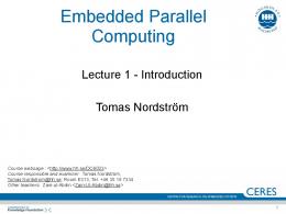
where ξ is a random vector varying over a set Ξ ⊆ Rk . More precisely, we assume throughout that a family F of events, i.e. subsets of Ξ, and the probability distribution P on F are given. Hence for every subset A ⊆ Ξ that is an event, i.e. A ∈ F, the probability P (A) is known. Furthermore, we assume that the functions gi (x, ·) : Ξ → R ∀x, i are random variables themselves, and that the probability distribution P is independent of x. We will use a scenario analysis approach to model uncertainty. Discrete random variables, ξ, will be considered with a finite number of values, ξ ω , ω ∈ Ω. To simplify notation, we will replace ξ ω with ω and Ξ with Ω. Definition 1.1. A stage of a given time horizon is a set of consecutive periods where the realization of the uncertain parameters takes place. Definition 1.2. A scenario is one realization of the uncertain parameters along the stages of the given time horizon. 10
1.7
t=1
t=2
Multistage stochastic mixed 0-1 optimization
t=3
t=4 10
ω=1
11
ω=2
5 T = {1, 2, 3, 4}
2 6
1
3
12
ω=3
Ω = Ω1 = {1, 2, . . . , 8}
13
ω=4
Ω2 = {1, 2, 3}
14
ω=5
7
G = {1, . . . , 17} G2 = {2, 3, 4}
8
15
ω=6
16
ω=7
17
ω=8
A5 = {1, 2, 5}
4 9
Figure 1.2: An example of scenario tree
Definition 1.3. A scenario group for a given stage is the set of scenarios with the same realization of the uncertain parameters up to the stage. The notation related to the scenario tree to be used through this work, illustrated in Figure 1.2, is as follows: T , set of stages along the time horizon, such that T = |T | is the last stage. T t , set of ancestor stages to stage t (including itself) whose variables have nonzero elements in the constraints of stage t ∈ T Ω, set of scenarios, where ω ∈ Ω represents a specific scenario. G, set of scenario groups, so that there is a tree whose set of nodes is given by G. Gt , set of scenario groups in stage t, for t ∈ T (Gt ⊆ G). Ωg , set of scenarios in scenario group g, for g ∈ G (Ωg ⊆ Ω). Ag , set consisting of scenario group g and its ancestors, for g ∈ G. Note: Ag is only included by node g for g ∈ G1 . 11
Chapter 1
Introduction
wω , likelihood that the modeler associates with scenario ω, P (ξ = ξ ω ) = wω , such P that ω∈Ω wω = 1. wg , weight factor representing the likelihood that is associated with scenario group P g, for g ∈ G. Note: wg = ω∈Ωg wω Let xt and y t denote the nx(t)- and ny(t)-vectors of the 0-1 and continuous variables, respectively, in the following deterministic model, min s.t.
X
(at xt + bt yt )
t∈T X
(Att′ xt′ + Btt′ yt′ ) = ht
∀t ∈ T
(1.3)
t′ ∈T t
xt ∈ {0, 1}nx(t) , 0 ≤ yt ≤ yˆt ∀t ∈ T ,
where at and bt are the row vectors of the objective function coefficients, respectively, ht is the m-column rhs, Att′ and Btt′ are the m × nx(t) and m × ny(t) constraint matrices, respectively, for stages in T t , and yˆt is the upper bound vector of variables in vector yt , for t ∈ T . Note: T 1 is only included by stage t = 1. The model must be extended in order to deal properly with the uncertainty in the values of some parameters. Thus, an approach to model the uncertainty in the problem data is needed. Model (1.3) can be extended to consider uncertainty in some of the main parameters. Many of today’s approaches to stochastic optimization are scenariobased approaches to deal with the uncertainty. The information structure is visualized as a tree, where each root-to-leaf way represents one specific scenario and corresponds to one realization of the whole set of the uncertain parameters, see Figure 1.2. Each node in the tree can be associated with a scenario group, such that two scenarios belong to the same group in a given period, provided that they have the same realization of the uncertain parameters up to the period. Given the non-anticipativity principle, both scenarios should have the same value for the related variables with the time index up to the given period. This research does not distinguish between a scenario group and the corresponding node in the tree (with the same number). For basic concepts and detailed introduction to stochastic optimization, see the books by Birge and Louveaux [2011]; Alonso-Ayuso et al. [2009]; Pflug and Pichler [2014], among others. Different types of models can be presented depending upon the type of recourse to consider, namely, simple, partial and full recourse. Let us consider the minimization of the objective function expected value with multiperiod full recourse, i,e., the risk neutral strategy. In this case, the compact representation of the stochastic version 12
1.7
Multistage stochastic mixed 0-1 optimization
of model (1.3) has the following Deterministic Equivalent Model (DEM) by groups, z DEM = min X
s.t.
(Agq xq +
X
wg (ag xg g∈G Bqg yq ) = hg
+ bg y g ) ∀g ∈ G
(1.4)
q∈Ag
xg ∈ {0, 1}nx(g) , 0 ≤ yg ≤ yˆg
∀g ∈ G,
where ag and cg are the row vectors of the objective function coefficients, Agq and B gq are the constrains matrices for vectors xq and yq in the system related to scenario group g, respectively, bg is the rhs, xg and yg are the vectors of the variables of scenario group g, and yˆg is the upper bound vector of variables in vector yg , for g ∈ G. All vectors and matrices have the appropriate dimensions. Hereafter, the components of xq (whose stage is t(q)) will be referred as linking variables, since they will directly affect the decision in stage t(g). On the other hand, splitting variable representation by stages can be expressed as follows, see Escudero et al. [2010b, 2012a], z DEM = min s.t.
X �
XX
wω aωt xωt + bωt ytω
ω∈Ω t∈T�
t,ω ω ω ω At,ω t′ xt′ + Bt′ yt′ = ht
t′ ∈T t ′ xωt − xωt = 0 ′ ytω − ytω = 0 ω xωt ∈ {0, 1}nxt
�
∀ω ∈ Ω, t ∈ T
∀ω, ω ′ ∈ Ωg : ω 6= ω ′ , g ∈ Gt , t ∈ T
(1.5)
∀ω, ω ′ ∈ Ωg : ω 6= ω ′ , g ∈ Gt , t ∈ T ω
ytω ∈ R+nyt , ∀ω ∈ Ω, t ∈ T ,
where aωt and bωt are the objective function coefficients of the variables xωt and ytω t,ω ′ t for stage t ∈ T under scenario ω ∈ Ω, respectively, and At,ω t′ and Bt′ ∀t ∈ T are ω ω the constraint matrices, for the xt′ and yt′ variables in the constraints related to ′ ′ stage t ∈ T , respectively. Note that xωt − xωt = 0 and ytω − ytω = 0 are the NAC. Finally, nxωt and nytω denote the dimensions of the vectors of the x and y variables, respectively, related to stage t under scenario ω. Following the nonanticipativity principle, the corresponding equalities must be satisfied for stage t, aωt = ag , bωt = bg , hωt = hg , ∀ω ∈ Ωg , g ∈ Gt , t ∈ T At,ω t′
=
Agq , Btt,ω ′
=
Bqg ,
′
t
g
∀q ∈ Gt′ , t ∈ T , ω ∈ Ω , g ∈ Gt
13
(1.6) (1.7)
Chapter
Parallel computing in optimization Diviser chacune des difficultés en autant de parcelles qu’il se pourrait, et qu’il serait requis pour les mieux résoudre. Divide each difficulty into as many parts as is feasible and necessary to resolve it. René Descartes, Le Discours de la Méthode
2.1
Introduction
This chapter presents the main ideas of Parallel Computing applied to Stochastic Optimization in two directions, namely, parallel solving of multiple problems and a parallel branching solving process of a single problem. First, a general environment is presented for parallel computing when solving several optimization problems by a message-passing paradigm code and its extension to a combined distributed memory/shared memory parallelization. We present the corresponding software/hardware environment, the scheme of the parallelization strategy and the basics of the programming syntax used in its implementation. We show the variation of computing time depending on the number of threads used and the selected solver in the computational experience we are reporting. This will lead to a comparison between the serial version and the different parallel strategies to solve a set of mixed integer optimization problems and, ultimately, to conclude that the parallel paradigm shows a significant improvement. Second, the Parallel Computing based approach for improving the process to solve a single mixed 0-1 stochastic problem is analysed. We present an extension of the Branch & Bound (B&B) algorithm, the so-called Multipath Branch & Bound 15
2
Chapter 2
Parallel computing in optimization
scheme in which the original binary variable tree is split among threads, i.e. parallel node branching, and iterative communication, allowing an earlier branch pruning by incumbent gathering. An illustrative example shows the reduction of branching nodes for each thread, due to the parallel features. In addition to the simultaneous branching, a stage perspective approach results in shorter computing time when applying the Multipath Branch & Bound scheme to a smaller scale problem; these features will be deeply exploited by the BFC algorithm proposed in Chapter 3 and Chapter 5. The conclusions of this chapter lead to define the inner and outer parallelization paradigms to be applied to decomposition algorithms presented in Chapter 3 and Chapter 4. The rest of the chapter is organized as follows: Section 2.2 presents the main concepts of a message-passing parallelization environment. Section 2.3 describes the parallel solving of multiple optimization and reports a computational experience. Section 2.4 defines the inner parallelization paradigm based on the results of the previous section. Section 2.5 introduces the Multipath Branch & Bound algorithm intended to solve optimization problems by parallel branching. Section 2.6 defines the outer parallelization paradigm based on the Multipath Branch & Bound performance conclusions. Section 2.7 summarizes the main conclusions.
2.2
Message-passing parallelization
The main idea behind message-passing parallelization is that every task thread receives an exact copy of the executable and, as there are not shared variables, the information exchange is performed by a message-passing environment. The task distribution is achieved by a thread rank (thread identification number) based branching, in other words, defining the rank of the thread that will perform a specific statement or by branching data vectors by rank. This allows it to work on a Single Program Multiple Data (SPMD) paradigm. Let us start the description of the MPI environment by underlining the three main phases that appear at machine level on a message-passing paradigm, see Pacheco [1996]. These phases are not directly executed by the user and they are automatically performed by the machine. Phase a: The user issues a directive to the operating system which has the effect of placing a copy of the same executable program on each task thread. Phase b: Each task thread begins executing its copy of the executable. Phase c: Different task threads can execute different statements by branching within the program. Typically branching will be based on thread ranks. 16
2.2
Message-passing parallelization
The implementation of the corresponding executable supports different experimental codes. Figure 2.1 presents the general structure of an MPI implementation in C++, see Pacheco [1996]. This layout can be divided into five groups by considering the nature of the functions they use. Appendix A describes the layout groups of the general MPI program.
... #include "mpi.h" ... main(int argc, char **argv) { ... // Group 1: Declaring MPI variables. ... // Group 2: Beginning of the MPI environment (No MPI functions called before this). ... // Group 3: Functions controlling the number of processes. ... // Group 4: Communication functions. ... // Group 5: Finishing the MPI environment (No MPI functions called after this). ... ... } ...
Figure 2.1: General structure of a MPI implementation
The full C++ code that we have developed for the parallel solving of several mixed integer optimization problems is described in Aldasoro et al. [2012]. In addition, a summarized and schematic version of the same code has been attached as Appendix A to this thesis. Note that the short version of the code is not an executable file but a useful tool for presenting its general structure. 17
Chapter 2
2.3
Parallel computing in optimization
Parallel computing to solve multiple optimization problems
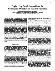
The serial solving of multiple optimization problems consists of reading the data files, creating the optimization models, solving them and reporting the corresponding results, see Figure 2.2 for solving 44 problems.
0.0 READ DATA {F.01, F.02, F.03, F.04, . . . , F.44} CREATE MODELS {F.01, F.02, F.03, F.04, . . . , F.44} SOLVE MODELS {F.01, F.02, F.03, F.04, . . . , F.44} REPORT RESULTS {F.01, F.02, F.03, F.04, . . . , F.44}
Figure 2.2: Serial execution. Basic steps. We can extend this descriptive diagram to a two thread parallel version as shown in Figure 2.3 for solving 44 problems. In this case, the first three tasks are performed by both threads sharing the total amount of problems; it significantly reduces the total amount of time. Once the solving process is finished in both threads, the main thread gathers the numerical results by message-passing functions and reports them. The modeler can define the branching cited on the third block according to the desired parallel programming strategy. The following procedure illustrates the parallel computing key idea behind the example code given in Appendix A, see a parallel diagram illustrated in Figure 2.4. Observe that there is only a single main thread in this section (remember the basic concepts of Parallel Computing in Section 1.3).
Step 0: Declaring optimization and MPI variables. [All task threads] Step 1: Definition of the global environment. [All task threads] • Beginning the MPI environment using functions presented in Section A.2 18
2.3
Parallel computing to solve multiple optimization problems
0.0
1.0
READ DATA {F.01, F.02, F.03, F.04, . . . , F.22}
READ DATA {F.23, F.24, F.25, F.26, . . . , F.44}
CREATE MODELS {F.01, F.02, F.03, F.04, . . . , F.22}
CREATE MODELS {F.23, F.24, F.25, F.26, . . . , F.44}
SOLVE MODELS {F.01, F.02, F.03, F.04, . . . , F.22}
SOLVE MODELS {F.23, F.24, F.25, F.26, . . . , F.44}
REPORT RESULTS {F.01, F.02, F.03, F.04, . . . , F.44}
send results
Figure 2.3: MPI based parallel execution. Basic steps.
Defining the total number of task threads, the thread rank of each of them and creation of a new communicator by using functions presented in Section A.3. By default, thread ranked 0 is defined as main thread. Step 2: Presolve assigned models. [All task and auxiliary threads] Every task thread reads the corresponding information and creates the associated optimization models. • If selected optimizer allows multiple auxiliary threads: Each task thread starts a shared memory parallel computing environment with a chosen number of auxiliary threads. An illustrative diagram is depicted in Figure 2.4 that corresponds to using 2 task threads and 4 auxiliary threads per task thread. Assigned models are presolved. • If selected optimizer only allows a single auxiliary thread: Each task thread presolves assigned models. Step 3: Global MPI communication. [All task threads] The main thread gathers the presolve information of all models and all task threads gather presolve status by using functions presented in Section A.4 Step 4: Check the presolve status [Main thread] • If all models are feasible and bounded: Go to Step 5. 19
Chapter 2
Parallel computing in optimization
Step 0
0.0
1.0
Step 1
DEFINE GLOBAL VARIABLES npr, assignment, inicial...
DEFINE GLOBAL VARIABLES npr, assignment, inicial...
Step 2
DEFINE LOCAL VARIABLES pid, zq_loc, x0_loc ...
DEFINE LOCAL VARIABLES pid, zq_loc, x0_loc ...
READ ASSIGNED MODELS
READ ASSIGNED MODELS
CREATE ASSIGNED MODELS
CREATE ASSIGNED MODELS
0.0
0.1
0.2
0.3
1.0
SHARED PRESOLVE OF ASSIGNED MODELS Step 3
1.2
1.3
SHARED PRESOLVE OF ASSIGNED MODELS
thread 0.0 gathers presolve information all primary threads gather presolve status
no
no
feasible and bounded?
Step 4
feasible and bounded?
yes Step 5
1.1
0.0
yes
0.1
0.2
0.3
SHARED SOLVING OF ASSIGNED MODELS Step 6
thread 0.0 gathers solve information
Step 7
REPORT ALL RESULTS
Step 8
END
1.0
1.1
1.2
1.3
SHARED SOLVING OF ASSIGNED MODELS
END
Figure 2.4: Parallelization diagram (1 main × 2 task × 4 auxiliary) threads
• Else: Go to Step 8. Step 5: Solve assigned models. [All task and auxiliary threads] • If selected optimizer allows multiple auxiliary threads: Each task thread starts a shared memory parallel programming environment with a chosen number of auxiliary threads (see Figure 2.4). Assigned models are solved. • If selected optimizer only allows a single auxiliary thread: Each task thread solves assigned models. Step 6: Global MPI communication. [All task threads] The main thread gathers the presolve information of all models by using functions presented in Section A.4 20
2.3
Parallel computing to solve multiple optimization problems
Step 7: Report results [Main thread] The main thread reports all results. • Finishing the MPI environment using functions presented in Section A.5 Step 8: Execution ends in all task threads. [All task threads]
2.3.1
Preliminary computational testing
Before performing the experiments we conducted some preliminary testing, in order to have an initial characterization of the parallelization environment. To do so, we have implemented the simplest possible parallel strategy, i.e., the strategy with the steps described in Section 2.3 without the final gather of information. In this context threads work in a fully independent way, and are only connected at the very beginning to distribute the models to solve. As a consequence, the parallel executions will not necessarily end simultaneously. The chosen solver is COIN-OR V1.3.1, which does not support multiple auxiliary threads. The work load consists of three different mixed 0-1 optimization problems repeated 3 times, i.e., a total amount of 9 instances to be solved by an increasing amount of threads in order to check the effect of the unbalanced work load, that is, the bottle-neck effect. Another aspect to analyse is the behaviour of the computational cluster regarding the communication time. It should be reduced as far as possible since it impacts the efficiency of the execution. As preliminary testing we will allow the ARINA computational cluster to select the threads to be used, see Section 1.5. The results are summarized in Table 2.1. Table 2.1: Preliminary test. COIN-OR. 9 instances.
Serial MPI
Available threads 1 1 2 3 4 5 6 7 8 9
Maximum # prob/thread 9 9 5 3 3 2 2 2 2 1
1 206 213 280 118 110 81 127 112 199 97
21
execution 2 3 4 159 205 214 212 254 222 273 237 270 153 229 225 190 195 170 104 120 102 229 239 134 118 162 174 183 226 226 105 72 86
5 238 265 386 135 194 184 100 287 221 60
Elapsed time Average St. dev. 204.4 28.7 233.2 24.6 289.2 56.6 172 51.7 171.8 36 118.2 39.3 165.8 63.6 170.6 70.4 211 19.2 84 18.3
Chapter 2
Parallel computing in optimization
To conclude, we can make several observations. First, the variability of the elapsed time is highly significant, in other words, the necessary time to create the MPI environment depends on the chosen threads and the machine work load situation. Consequently from now on in this thesis the user will specifically select the threads to be used, ideally being part of the same computing node in order to reduce communication time. Second, the absence of further communication among threads once the solving process has started produces a chaotic behaviour with regard to the elapsed time. Therefore, the other implementations reported in this work consider intermediate communication among threads in order to guarantee the most simultaneous execution as possible. Additionally, following the criterion that is very frequently found in the general literature, the number of threads to be used will be a power of 2, since it is fast and convenient to implement in a computer. Taking the above conclusions into account, the next subsection presents a broad computational experience on comparing parallel and serial versions of decomposition algorithms solve a set by instances of a medium-scale optimization problem.
2.3.2
Computational experience
The computational experiments were conducted in the ARINA computational cluster at SGI/IZO-SGIker, Universidad del País Vasco, UPV/EHU, see Section 1.5. For the reported experiments, Intel Xeon type computing nodes were used, consisting of 8 cores with 48Gb of RAM, see Table 1.1. The optimization problems were solved using COIN-OR V1.3.1 and CPLEX v12.2 from COIN-OR V1.3.1 environment. The set of instances whose computational experience is analysed in this subsection is based on the scenario-cluster submodels obtained from the multistage stochastic mixed 0-1 problem P4 taken from the computational experience reported in Escudero et al. [2012a] and countered as one of the problems included in Testbed 2 whose results are reported in Table 3.2. The full model is a medium-scale problem with |Ω| = 217 scenarios (structured in nonsymmetric scenario tree) and |T | = 4 stages, where the nonanticipativity constraints are relaxed for the first and second stage, in order to generate the 44 instances considered in this subsection. The dimensions of the original medium-scale optimization problem and the related average and standard deviation of the dimensions of the subproblems are shown in Table 2.2 and Table 2.3, respectively. The headings of the table are as follows: m, number of constraints; nx, number of 0-1 variables; ny, number of continuous variables; nel, number of nonzero coefficients in the constraint matrix and dens, constraint matrix density (in %). Table 2.4 shows the value of the optimal 22
2.3
Parallel computing to solve multiple optimization problems
objective function for the 44 mixed integer problems. Table 2.2: Medium-scale problem dimensions m 9248
nx 2176
ny 4792
nel 515768
dens 0.64
Table 2.3: Subproblem average (standard deviation) dimensions.
average (st. deviation)
m 270 (53.46)
nx 63 (12.58)
ny 151 (251.16)
nel 14263 (2981.38)
dens 7.93 (1.57)
Table 2.4: Solution values for the 44 subproblems. Testbed 1. F.1 F.2 F.3 F.4 F.5 F.6 F.7 F.8 F.9 F.10 F.11
-2953.46 -5067.97 -3957.70 -5310.86 -9219.36 -6539.62 -8196.80 -6582.53 -7811.68 -8126.43 -8420.17
F.12 F.13 F.14 F.15 F.16 F.17 F.18 F.19 F.20 F.21 F.22
-3215.94 -6662.71 -4078.15 -5315.24 -8504.21 -6592.45 -5186.78 -6291.11 -7378.17 -8450.21 -8558.38
F.23 F.24 F.25 F.26 F.27 F.28 F.29 F.30 F.31 F.32 F.33
-8945.76 -7271.52 -7136.25 -7046.85 -5561.61 -5327.66 -3991.81 -8051.70 -4887.34 -5434.41 -9432.48
F.34 F.35 F.36 F.37 F.38 F.39 F.40 F.41 F.42 F.43 F.44
-2915.80 -4291.44 -9412.94 -7899.80 -4851.96 -7735.64 -7764.66 -9828.10 -2786.57 -4311.35 -8135.21
Table 2.5 and Table 2.6 show the main execution times for COIN-OR optimizer and for CPLEX solver within COIN-OR (allowing one single auxiliary thread for CPLEX), respectively. The headings are as follows: Available threads (th), the number of threads for the serial and parallel programming; Maximum # prob/thread, l m C the bottleneck or maximum number of problems to be solved by thread, that is, th ; Min, Average, Max, the minimum, average and maximum CPU time by thread (in seconds), respectively; Average, St. dev., the average and standard deviation (in seconds) for the elapsed time after 15 executions of the same code. CPLEX being called from COIN-OR is between 3 and 5 five times faster than own COIN-OR optimizer (without any presolving or cut generation). Note that the CPU time measures the instruction processing time of the computer program whereas the elapsed time (also known as real time or wall-clock time) includes the CPU time, the input/ouput time and the communication delay. We can conclude that the CPU time and the elapsed time are not significantly different, therefore, throughout this memoir elapsed time will be the analysed magnitude. 23
Chapter 2
Parallel computing in optimization Table 2.5: Computing times under COIN-OR. Testbed 1.
Serial MPI
Available threads 1 1 2 4 8 16 32 64
Maximum # prob/thread 44 44 22 11 6 3 2 1
Min. 17.651 18.013 8.823 5.018 3.118 1.735 1.239 0.839
CPU time Average Max. 17.651 17.651 18.013 18.013 8.866 8.779 5.165 5.271 3.647 3.960 2.077 2.272 1.857 1.996 1.403 1.517
Elapsed time Average St. dev. 17.780 0.013 18.239 0.093 8.972 0.010 5.373 0.029 4.508 0.253 2.632 0.270 2.054 0.005 1.590 0.260
Table 2.6: Computing times under CPLEX (single auxiliary thread). Testbed 1.
Serial MPI
Available threads 1 1 2 4 8 16 32 64
Maximum # prob/thread 44 44 22 11 6 3 2 1
Min. 6.107 6.344 3.161 1.647 0.992 0.521 0.349 0.227
CPU time Average 6.107 6.344 3.165 1.667 1.025 0.546 0.390 0.259
Max. 6.107 6.344 3.168 1.685 1.074 0.564 0.405 0.276
Elapsed time Average St. dev. 6.163 0.019 6.401 0.005 3.201 0.002 1.706 0.005 1.120 0.030 0.604 0.058 0.426 0.0175 0.297 0.0857
Table 2.7 shows the execution times for CPLEX solver from COIN-OR considering a number of available threads and several combinations between the number of threads for distributed memory (task threads) and shared memory (auxiliary threads). The other headings are as denoted in the previous tables. For 8 available threads the average elapsed time for computing the serial execution is 7.699 seconds, which corresponds to the worst strategy. Figure 2.5 shows the elapsed time for COIN-OR in horizontal read line and the elapsed time for CPLEX in vertical blue bars, it is classified according to the available number of threads, as detailed in Tables 2.5 and 2.7. We can observe that for a fixed number of available threads the elapsed time to solve the 44 problems (a large number of them with small dimensions) decreases when the number of MPI threads increases. So, the fastest case corresponds to the highest number of task threads and a single auxiliary thread for CPLEX, which highlights the interest of MPI parallel computing. Finally, Table 2.8 summarizes the best elapsed times for COIN-OR and CPLEX, with all the available threads considered. The headings are as follows: Elapsed Time, the wall clock time in seconds (average time over 15 realizations); Sth , speedup, serial elapsed time over parallel elapsed time; and Eth %, efficiency, speedup over number of 24
2.3
Parallel computing to solve multiple optimization problems
Table 2.7: Computing times under CPLEX (multiple auxiliary threads). Testbed 1. Available task × auxiliary CPU time threads threads Min. Average 1 1×1 6.107 6.107 2 1×2 4.328 4.328 2 2×1 3.161 3.165 4 1×4 2.382 2.382 4 2×2 2.141 2.184 4 4×1 1.647 1.667 8 1×8 2.590 2.590 8 2×4 1.184 1.229 8 4×2 1.095 1.124 8 8×1 0.992 1.025 MPI= 1 corresponds to serial execution
8
8
6
6
6
4
4
4
10
COIN
CPLEX
2
8x1
4x2
2x4
1x8
4x1
2x2
1x4
0
2 0 2x1
1x2
0 1x1
0
2
5
Elapsed time (seconds)
15
8
8 threads
10
4 threads
10
2 threads
10
20
1 thread
Elapsed time Average St. dev. 6.163 0.019 5.683 0.046 3.201 0.002 6.076 0.055 2.986 0.022 1.706 0.005 7.699 0.222 3.229 0.245 1.632 0.032 1.120 0.030
Max. 6.107 4.328 3.168 2.382 2.227 1.685 2.590 1.258 1.176 1.074
Figure 2.5: Classification for (task × auxiliary) threads execution time
threads, in percentage. The speedup and efficiency is high and similar in both solvers for th= 2 and th = 4 available threads, but it is better for CPLEX optimization solver for 8 or more threads. These results are illustrated in Figure 2.6.
25
Chapter 2
Parallel computing in optimization Table 2.8: Efficiency of COIN-OR and CPLEX. Testbed 1.
100
CPLEX Elapsed time Sth 6.163 1.000 3.201 1.925 1.706 3.613 1.120 5.503 0.604 10.204 0.426 14.670 0.297 20.751
Eth % 100.0 96.3 90.3 68.8 63.8 45.8 32.4
60
80
CPLEX COIN
40
30
40
Efficiency (%)
50
Eth % 100.0 99.1 82.7 49.3 42.2 27.1 17.5
Number of threads
64
32
16
2 4 8
64
32
16
2 4 8
0
0
10
20
20
Speedup
COIN-OR Elapsed time Sth 17.780 1.000 8.972 1.982 5.373 3.309 4.508 3.944 2.632 6.755 2.054 8.656 1.590 11.182
CPLEX COIN Ideal
60
Serial MPI
Available threads 1 2 4 8 16 32 64
Number of threads
Figure 2.6: Speedup and efficiency vs number of threads
2.4
Inner parallelization paradigm
The truly potential of the strategy presented in Section 2.3 to solve multiple optimization problems in parallel consists of its insertion into an iterative algorithm. In other words, the parallelization environment can work as an iterative step of a decomposition algorithm to solve large-scale problems, parallelizing the resolution of the corresponding subproblems. We could define this new approach as inner parallelization since it works as an internal parallelization of a serial algorithm. The inner parallelization paradigm is applied to an exact decomposition algorithm in Chapter 3 as well as to a matheuristic decomposition algorithm in Chapter 4.
2.5
Multipath Branch & Bound Algorithm
Once the MIP optimization model is split among submodels whose optimization is assigned to the chosen solver executions, let us improve each solving process in large-scale problems. The internal parallel mode of any solver is an efficient black 26
2.5
Multipath Branch & Bound Algorithm
box for the user, however, two weak points can be identified, namely, its parallel resources are limited (up to 8 auxiliary threads are allowed under academic license for the state-of-the-art optimizer CPLEX) and what is more difficult to overcome in the near and medium future, the current solvers do not profit from the problem structure. Therefore, this section analyses potential improvements in this direction, leading to more complex solving environments. In this section a parallel computing framework is presented to solve a large-scale MIP problem. Based on the serial Branch & Bound algorithm, it includes two new aspects drawn from weak points in the current solvers: simultaneous branching and stage perspective.
2.5.1
Simultaneous branching
The serial Branch & Bound algorithm is a tool to solve mixed 0-1 problems by obtaining its optimal solution. A linear programming problem is solved in every node of a branching tree where the branching and pruning criteria ensures that the non visited nodes are suboptimal. However, the number of visited nodes and, therefore, the execution time, increases significantly for medium and large-scale problems. Parallel computing can reduce the execution time of the serial Branch & Bound algorithm, as different approaches can be found throughout the literature. Note that the paradigm presented in Section 2.4 cannot be directly applied, since it solves several problems in parallel and each node of the Branch & Bound consists of a single problem. Nevertheless, this idea can be adapted to visiting several nodes at the same time, that is, a parallel visiting of Branch & Bound nodes. This simultaneous branching paradigm can be defined in several ways, such as a main thread can lead the tree branching and several task threads can solve the neighbour nodes or, more interestingly, the original problem tree can be split into parts. The second option allows several simultaneous Branch & Bound executions to be worked with, in other words, the original tree is branched by several paths, each managed by a main thread. Thus, the serial version can be considered as a one-path Branch & Bound. Multipath B&B Algorithm As previously mentioned, the Multipath Branch & Bound algorithm splits the branching tree among paths. Consequently, each resulting tree will have a smaller size since a modeler-driven set of integer variables from the original problem will be fixed to integer values. Additionally, the communication capability of MPI can be used for interacting 27
Chapter 2
Parallel computing in optimization
among the paths. The incumbent solution could be updated by gathering the best feasible solution from among all main threads, allowing an earlier pruning of the branches. Moreover, as in general different paths need to visit a different number of nodes they will not usually end simultaneously. Once a main thread ends the algorithm execution, it is considered a dead path, but it does not mean that its computational power is not to be used any more, since the Synchronization Phase can be started. It consists of splitting an active path (a non-dead one) into two paths, with one of them being assigned to the original main thread and the second one to a main thread in dead status. Algorithm 2.1 and Figure 2.7 schematically presents the steps of the algorithm. This parallelization paradigm assures that the full parallel power is used during the whole execution. It behaves very efficiently for big branching trees for mediumscale or non divisible problems, see below. A step-by-step numerical example Considering that a numerical example can make it easier to understand the mechanism of the outer parallelization by multipath branching, let us consider a 0-1 Knapsack optimization problem. This family of problems has the characteristic of being purely binary and having only a single inequality constraint. We consider that it is an appropriate environment for following the steps of the Multipath Branch & Bound algorithm without loose of generality. Let us consider the following Knapsack problem: z = max 23x1 + 19x2 + 28x3 + 14x4 + 44x5 s.t. 8x1 + 7x2 + 11x3 + 6x4 + 19x5 ≤ 25 x1 , x2 , x3 , x4 , x5 ∈ {0, 1}
(2.1)
Table 2.9 shows the branching nodes and their solution for a serial Branch & Bound algorithm. Figure 2.8 depicts the related branching tree. Table 2.10 and Table 2.11 and Figure 2.9 and Figure 2.10 resume the resolution by two-path and four-path, respectively, from the application of the Multipath Branch & Bound algorithm. Before starting, let us describe the branching criteria, valid for all strategies. The first branching side for any variable non yet 0-1 valued is the 0 value. Additionally, if the resolution of a LP relaxed problem gives as a result 0-1 values for some variables, then the algorithm temporally fixes those variables to the solution values and branch on the next one. 28
2.5
Multipath Branch & Bound Algorithm
Algorithm 2.1: Multipath Branch & Bound Every main thread executes: Step 0: (Initializations) Define the initial starting point of each path and fix the variables for each of them. Step 1: (Branch) The branching criterion could be modified by the user, such as depth-first, 0-first etc. Step 2: (Solve relaxed model) The corresponding relaxation of the original problem is solved in serial by a unique main thread. The value of the objective function is stored in the local zpath variable. Step 3: (Gather zpath ) All paths gather zpath values. Note that this step works as a synchronization phase since all main threads must arrive here in order to execute the communication. The values are stored at a solution vector zvect . If there is not any feasible solution of the original problem in zvect , then go to Step 1. If there is a feasible solution of the original problem, at least, in zvect , then store the best solution value at the local variable z ∗ . Step 4: (Update incumbent) Update the incumbent value, if minimization problem then z DEM := min(z DEM , z ∗ ). if maximization problem then z DEM := max(z DEM , z ∗ ). Step 5: (Prune) Check if the branch can be locally pruned, (i.e., at the current node), or if the branch can be pruned from an upper position (this can be done when the incumbent solution value is updated with a solution coming from a different main thread). Step 6: (Gather execution status) All paths gather execution status, knowing which paths are dead and which are still active. If all paths are dead, then STOP. Step 7: (Redefine path platform) If there are death paths, the same amount of active path are split in two active paths and the main threads related to dead paths are reassigned to active paths.
29
Chapter 2
Parallel computing in optimization SET PATH PLATFORM
BRANCH
BRANCH
SOLVE NODE
SOLVE NODE
ALL PATHS GATHER z
no
any feasible?
any feasible?
yes
yes
UPDATE INCUMBENT
UPDATE INCUMBENT
CHECK LOCAL OR UPPER PRUNE
CHECK LOCAL OR UPPER PRUNE
no
ALL PATHS GATHER EXECUTION STATUS
GLOBAL END
yes
all paths dead?
all paths dead?
no
no
yes
GLOBAL END
REDEFINITION OF PATH PLATFORM: DEAD PATHS ARE REASSIGNED
Figure 2.7: Multipath Branch & Bound algorithm. Basic steps
One-path Branch & Bound (serial B&B) The serial Branch & Bound algorithm, understood as the one-path particular case of the Multipath Branch & Bound algorithm, starts at the root node of the tree. The first LP relaxed problem is solved obtaining a solution value of 67.45 and 0-1 values for x1 and x2 (see Table 2.9). Following the branching criteria the algorithm fixes x1 and x2 to 1 and branches x3 to 0. Once the second relaxation is solved we obtain to the third node, since the chosen problem is very small we are already at the last tree level with all variables fixed to a binary value. The 30
2.5
Multipath Branch & Bound Algorithm
corresponding resolution gives an objective value of 56, and moreover, this solution is feasible at the original problem (which is why the node is coloured in green in Figure 2.8) and we can update the incumbent solution from −∞ to 56. Table 2.9: One-path solving process. Solutions node 1a 2a 3a 4a 5a 6a 7a 8a 9a 10a a z1 = 67.45 z2 = 65.26 z3 = 56 z5 = 65.16 z6 = 42 z9 = 65 z10 = 63.32
x1 1 1 1 1 1 1 1 1 1 0
x2 1 1 1 1 1 1 1 1 0 1
x3 0.91 0 0 0 0 0 0 1 1 1
x4 0 1 1 1 0 0 0 0 1 1
x5 0 0.21 0 1 0.53 0 1 0 0 0.05
zpath 67.45 65.26 56 infeasible 65.16 42 infeasible infeasible 65 63.32
z DEM −∞ −∞ 56 56 56 56 56 56 65 65
1a
x1 = 1
x1 = 0 10a
x2 = 1
x2 = 0 9a
x3 = 0 x3 = 1
2a
8a
x4 = 1 x4 = 0 5a
x5 = 1 x5 = 1 x5 = 0 x5 = 0 6a
7a
3a
4a
Figure 2.8: Knapsack problem example. One-path B&B Then we branch variable x5 to 1, obtaining an infeasible problem (yellow coloured node) so we go up to the first non branched node (in this case node 2) and we keep 31
Chapter 2
Parallel computing in optimization
the same branching criteria. After visiting several nodes we obtain to node 9, having x1 and x2 branched to 1 and 0 respectively, the resolution of the relaxation shows a feasible solution of the original problem, updating the incumbent solution to 65. Finally we branch the starting x1 variable to 0, analysing the second side of the tree. The relaxed solution gives an objective function value of 63.32, being smaller than the incumbent solution we can prune the branch (the blue ring at Figure 2.8 indicates the prune) and the algorithm will stop. Two-path Branch & Bound Now let us apply the same criteria to a two-path Branch & Bound, denoted with a and b superscripts respectively, see Table 2.10 and branching tree in Figure 2.9. Table 2.10: Two-path solving process. Solutions node 1a 2a 3a 4a 5a 6a 7a 8a 9a 1b 2b 3b 4b 5b 6b 7b 8b 9b
x1 0 0 0 0 0 0 0 0 1 1 1 1 1 1 1 1 1 1
x2 1 1 1 1 1 1 1 0 0 1 1 1 1 1 1 1 1 0
x3 1 1 1 1 1 1 0 1 1 0.91 0 0 0 0 0 0 1 0
x4 1 1 1 0 0 0 1 1 1 0 1 1 1 0 0 0 0 1
x5 0.05 0 1 0.37 0 1 0.63 0.42 0 0 0.21 0 1 0.53 0 1 0 0.58
zpath 63.32 61 infeasible 63.21 47 infeasible 60.79 60.53 65 67.45 65.26 56 infeasible 65.16 42 infeasible infeasible 62.47
z DEM −∞ 61 61 61 61 61 61 61 65 −∞ 61 61 61 61 61 61 61 65
The first change corresponds to the starting node, which is situated at the second level of the algorithm, saving the branch of the x1 variable. Both paths obtain an infeasible solution for the original problem (since not all variables have 0-1 values) so they keep branching. At the second node Path a obtains a feasible solution whose value is 61, whereas Path b obtains an infeasible solution of the original problem. Since Path a obtains a feasible solution for the original problem, its solution value 61 is the incumbent for both paths. Consequently at the z gather phase Path b will the 61 solution, both paths update 32
2.5 a z1 = 63.32 z2 = 61 z4 = 63.21 z5 = 47 z7 = 60.79 z8 = 60.53 z9 = 65
Multipath Branch & Bound Algorithm
x1 = 1
x1 = 0 1a
x2 = 0
b z1 = 67.45 z2 = 65.26 z3 = 56 z5 = 65.16 z6 = 42 z9 = 62.47
1b
x2 = 1
x2 = 1
x2 = 0
8a
x3 = 0 x3 = 1
x3 = 0 x3 = 1
7a
9b
x3 = 0 x3 = 1
9a
2b
x4 = 1
x4 = 1
x4 = 0
x4 = 0
a
5b
4
x5 = 1 x5 = 1 x5 = 0 x5 = 0 5a
8b
6a
2a
3a
x5 = 1 x5 = 1 x5 = 0 x5 = 0 6b
7b
3b
4b
Figure 2.9: Knapsack problem example. Two-path B&B
the incumbent to 61. They both check if it is possible to perform a local o upper prune of the branch, as it is not the case they keep branching. After visiting several nodes, Path a is capable of pruning nodes 7 and 8. At this point Path a is dead and Path b needs to branch x3 to 0, this is when the Synchronization Phase takes place, moving Path a to the Path b side and branching x3 to 1. Now nodes 9a and 9b are solved and the solutions 65 and 62.47 are obtained respectively, gathering those values both branches update incumbent value to 65. Consequently, both paths can locally prune the branch and both paths are dead, so the algorithm stops. In this example the three advantages of the multipath version of the Branch & Bound algorithm can be observed: The starting node has a lower level than in the serial version, paths exchange solutions allowing a faster update of the incumbent solution and finally the reassignment phase ensures that main threads are working without a break. On the other hand, in this case the number of visited nodes by the longest branch is only slightly smaller, 9 compared to 10. Let us check if the use of more paths improves that behaviour. 33
Chapter 2
Parallel computing in optimization
Four-path Branch & Bound Table 2.11: Four-path solving process. Solutions
a z1 = 60.53 z2 = 56
node 1a 2a 3a
x1 0 1 1
x2 0 1 1
x3 1 0 1
x4 1 1 1
x5 0.42 0 0
zpath 60.53 56 infeasible
z DEM 65 65 65
1b 2b 3b 1c 2c 3c 1d 2d 3d
0 1 1 1 1 1 1 1 1
1 1 1 0 1 1 1 1 1
1 0 1 1 0 1 0.91 0 1
1 0 0 1 1 1 0 0 0
0 1 1 0 1 1 0 0 0
61 infeasible infeasible 65 infeasible infeasible 67.45 42 infeasible
65 65 65 65 65 65 65 65 65 c z1 = 65
b z1 = 63.32 x1 = 1
x1 = 0
x2 = 0 1a
d z1 = 67.45 z2 = 42
x2 = 1
x2 = 1
x2 = 0 1c
1b
1d
x3 = 0 x3 = 1
x4 = 1
x4 = 1
x4 = 0
x4 = 0
x5 = 1 x5 = 1 x5 = 1 x5 = 1 x5 = 0 x5 = 0 x5 = 0 x5 = 0 2d
2b
2a
2c
3d
3b
3a
3c
Figure 2.10: Knapsack problem example. Four-path B&B Let the four paths be notated a, b, c and d, and keep the same branching criterion. In this context, the starting point of the branching will be situated at the second 34
2.5
Multipath Branch & Bound Algorithm
level of the tree, saving the branching of variables x1 and x2 . The resolution of the LP relaxation of the first nodes gives the function values: 60.53, 63.32, 65 and 67.45. All solutions are gathered by the paths and note that the solution of Path c is feasible and the value is greater than those from Path a and Path b, consequently Path a, Path b and Path c can be locally pruned and they are now dead. These three paths are reassigned to Path d side, creating a same level branching for nodes 2a , 2b , 2c and 2d . Once the related LP relaxation is solved two feasible solutions (2a and 2d ) have been obtained but none of them improves the incumbent solution value. Given that those nodes are already at the last level, Path a, Path b and Path c are again dead, and then they are reassigned to Path d. All 3a , 3b , 3c and 3d are infeasible and, therefore, all paths are dead, and so, the algorithm stops. See Table 2.11 and branching tree in Figure 2.10 In addition to the aspects underlined at the previous strategies, the four-path strategy shows a significant reduction of visited nodes for each path (from 10 in serial to 3 in this case).
2.5.2
Stage perspective
The second key aspect referred to at the beginning of Section 2.5, corresponds to the stage perspective. Most of the state-of-the-art solvers (with CPLEX being one of them) have no structural vision of the stochastic problem, and therefore, they do not benefit from the variable hierarchy. However, decomposition algorithms can take advantage of this information. Let us analyse the potential effect of the variable order when solving a stochastic mixed 0-1 problem. To do so let us take the Multipath Branch & Bound algorithm as reference. In fact, preliminary tests can be enriched by adding preprocessing to Algorithm 2.1, see also Figure 2.7; so that initially tighter bound can be obtained and the values of the variables in a quasioptimal solution can be very useful for reducing the computations in the algorithm to obtain the optimal solution. Four possible set ups regarding the variable fixing criterion: always to zero (0), as presented on the knapsack example, always to one (1), the values obtained at the quasioptimal solution (Q) and the rounded solution of the LP relaxation (round(LR)). Computational experience Let us consider a mixed 0-1 problem in order to test the effect of set up parameters. Specifically, let problem P11 taken from the computational experience reported in Escudero et al. [2012a] and later included in Testbed 2 in Table 3.2. By applying a 35
Chapter 2
Parallel computing in optimization
break stage clustering process with t∗ (see Section 3.2), 5 subproblems are generated. The selected subproblem is the one related to cluster number 1. The computational experiments were conducted in the ARINA computational cluster at SGI/IZO-SGIker from UPV/EHU; using two Intel Xeon nodes with 8 cores and 48Gb of RAM (remember Table 1.1). The LP relaxation problems were solved by using CPLEX V12.2 from COIN-OR V1.3.1. The environment corresponds to 16 paths (using a single CPLEX auxiliary thread each) of Algorithm 2.1 (see also Figure 2.7) extended with an initial CPLEX preprocessing of 1% optimality gap. Table 2.12 shows the computing time (in sec) required for each fixing criterion and variable ordering. The headings are as follows: nominal, variables ordered by indexes; max to min difference, variables with largest difference between values at LP relaxation and quasioptimal solution first; min to max difference, variables with lowest difference between values at LP relaxation and quasioptimal solution first. It can be observed that the stage ordering is significantly faster than the group ordering. The fast execution of the stage ordering does not allow behaviour conclusions to be extracted, regarding the variable order or the fixing criterion. On the other hand, the group ordering shows that nominal variable ordering is more efficient than the ones linked to the increasing and decreasing differences between quasioptimal and LP relaxation solutions. Additionally, the fastest executions correspond to fixing variables according to the quasioptimal or rounded LP relaxation solution. However, as no branching criterion appears to significantly outperform the others, further research and computational experience is analysed in Chapter 5. Table 2.12: Effect of the variable order and the fixing criterion
FIXING CRITERION 0 1 Q round(LR)
2.6
Elapsed time (in seconds) Group-wise ordering Stage-wise ordering nominal max to min min to max nominal max to min min to max difference difference difference difference 220 242 552 9 9 10 62 118 1001 7 9 8 81 172 551 10 9 10 78 176 552 9 10 10
Outer parallelization paradigm
The Multipath Branch & Bound approach needs to analyse the whole variable tree in order to ensure optimality. If larger scale problems are considered, this aspect turns to be the main drawback and a significant obstacle to obtain the optimal solution in an acceptable elapsed time. However, the parallel branching environment presented 36
2.7
Conclusions
in this chapter is applicable to other branching algorithms that can deal with larger problems; notably, parallel branching algorithm based on decomposition. More generally, let us name outer parallelization paradigm to an environment where simultaneous executions of algorithms are interconnected. As in the Multipath Branch & Bound algorithm, each algorithm execution, or path, can have a different initial condition and can search solutions in a different part of the feasibility region. Communication among paths will allow each algorithm execution to take profit from more information than the one locally obtained by the algorithm. However, the enormous potential of the outer parallelization is based on the possibility of having different nature serial algorithms co-working in parallel by communication. The hybrid environments create a large research area where parallelconceived algorithms will profit from different paths working with a different role, such as exact and heuristic combinations.
2.7
Conclusions
As the results of the preliminary testing have shown, the hardware environment control is a key aspect in terms of obtaining satisfactory results. This control can be summarized in three aspects. First, user selection of the involved threads, trying to use architecturally close threads such as threads from the same computing node. Second, the behaviour tests should increase the number of threads by power of two, following the way threads are built to be used. Third, in order to avoid chaotic simultaneous executions it is highly recommended to introduce intermediate communication functions, used as synchronization phases. Regarding the parallel execution of several mixed 0-1 optimization problems the most important conclusion that we can withdraw is that distributed memory parallelization by MPI is a very powerful tool for reducing the execution time. The improvement is consistent when increasing the number of task threads in both COINOR and CPLEX solvers that we have experimented with, as shown in Table 2.5 and Table 2.6. Furthermore, Table 2.8 reports that CPLEX is a significantly faster solver than COIN-OR in the serial execution and has a better speedup and efficiency in parallel environments. Consequently, from now on in this work problems will be solved by CPLEX (from COIN-OR environment) and, then the use of COIN-OR as solver is discarded. The results showed in Table 2.8 for CPLEX are highly encouraging for further research, since its scaling behaviour is highly significant in both computing time and 37
Chapter 2
Parallel computing in optimization
elapsed time scales, achieving a speedup factor of 20.751 and an efficiency of 32.4 % when using 64 threads. Additionally, as previously reported in Figure 2.4, it is possible to combine user computed distributed memory with solver internal shared memory parallelization (i.e., CPLEX in the computational experience that has been reported). A group of executions has been carried out and summarized in Table 2.7 by fixing in each case the number of threads and varying the number of them associated to distributed and shared memory. In this case we can conclude that it is more efficient to assign threads to the distributed memory paradigm, i.e., task threads, rather than to combine it with CPLEX internal share memory paradigm, i.e., auxiliary threads. However, it is very important to underline that we are considering a group of small scale optimization problems and consequently we cannot conclude that its behaviour will be the same for large scale problems. We can therefore conclude that an efficient way has been introduced for parallel solving of several small scale mixed 0-1 optimization problems. Interestingly, this environment can be used for parallel subproblem solving of decomposition algorithms, i.e., an inner parallelization strategy; see Chapter 3 and Chapter 4 for detailed implementations. The outer parallelization strategy and logic differs from the inner parallelization by changing the focus from the micro scale to the macro scale, particularly in our context, from solving in parallel stochastic problems to branching the tree with multiple paths. Based on an illustrative example of the 0-1 Knapsack problem we have numerically presented the algorithm steps and diagram of the outer parallelization of the Branch & Bound algorithm. From that example we can observe that the Multipath B&B approach allows to reduce the elapsed time by visiting nodes in parallel, gathering intermediate solutions and reassigning dead paths. The use of that scheme seems really appropriate for small and medium scale B&B node problems since it has a more intensive use of threads than the inner parallelization. Additionally, we have analysed the effect of the variable ordering and fixing criterion on the algorithm performance. The stage-wise variable ordering shows a significantly faster behaviour but no clear branching criterion has been identified from the preliminary computational experience. In this chapter we have shown that parallel branching executions can be managed in a coordinated way and it can profit from the problem structure. It seems appropriate to go further in this analysis to try to solve larger problems, so the coordinated branching and the break stage concepts will work in this direction for the Branch-and-Fix Coordination algorithm considered in Chapter 3. 38
Chapter
Parallel Computing Branch-and-Fix Coordination algorithm Caminante, son tus huellas el camino, y nada más; caminante, no hay camino, se hace camino al andar.
Wanderer, your footsteps are the road, and nothing more; wanderer, there is no road, the road is made by walking.
Antonio Machado, Campos de Castilla.
3.1
Introduction
The aim of this chapter is to present the parallelized version of the Branch-and-Fix Coordination multistage (BFC) algorithm, see Escudero et al. [2012a], referred to as Parallel Branch-and-Fix Coordination multistage (P-BFC) procedure, so that the reduction in the elapsed time in problem solving is analyzed. The parallelization is performed at two levels. The inner level parallelizes the optimization of the Mixed Integer Programming (MIP) submodels attached to the set of scenario clusters to be generated by the modeler-defined break stage. The concept of break stage was introduced in Escudero et al. [2012a] as a way of decomposing the original problem, in which the nonanticipativity constraints (NAC) are partially relaxed from the mixture of the splitting and compact representations of the DEM of the stochastic problem. Several strategies are presented for analyzing the performance of using inner parallel computing based on MPI strategies for solving scenario cluster based subproblems versus the serial version of the BFC methodology. The outer level of parallelization is based on the path concept, see Section 1.3. In this chapter a path is defined by a main thread managing a serial Branch-and-Fix Coordination algorithm 39
3
Chapter 3
Parallel Branch-and-Fix Coordination
and the combinations of a set of 0-1 variables as initial condition, such that each one can itself be internally optimized with the inner parallelization scheme. The main results of a broad computational experience are reported to assess whether the performance of the parallel computing approach compares favorably to the serial one. The elapsed time required by outer-inner parallelization is very frequently some orders of magnitude smaller than that of the serial version of the algorithm, depending on the available computer resources . So, the larger the number of paths and task threads (in addition to the number of auxiliary threads that the MIP solver allows for itself), the smaller the elapsed time for problem solving. The rest of the chapter is organized as follows: Section 3.2 presents the main concepts of the break stage scenario clustering. Section 3.3 introduces the serial version of the scenario cluster BFC algorithm introduced in Escudero et al. [2010b, 2012a], additionally, the Parallel Computing implementations of the BFC algorithm are described, Inner (Section 3.4), Outer (Section 3.5) and combined Outer-Inner (Section 3.6). Section 3.7 reports the main results of a broad computational experience to assess the validity of the parallel version of the BFC algorithm versus its serial version and the plain use of a state-of-the-art MIP solver. Section 3.8 summarizes the main conclusions.
3.2
Break stage scenario clustering
The Break stage scenario clustering methodology consists of breaking the stochastic model in a set of independent scenario cluster subproblems with respect to a fixed stage, which is so named the break stage, due to the relaxation of the nonanticipativity constraints (NAC) up to that stage, see Escudero et al. [2012a]. ′
It is clear that the explicit representation of the NAC xωt − xωt = 0 and ′ ω yt − ytω = 0 in model (1.5) is not desirable for all pairs (ω, ω ′ ) of scenarios in order to reduce the model’s dimensions. So, we can represent implicitly the NAC for some pairs of scenarios in order to gain computational efficiency. We decompose the scenario tree into a set of scenario cluster subtrees, each one for a scenario cluster in the set denoted as C= {1, ...,C} with C = |C|, see below the reason for it. Let T Ωc denote the set of scenarios that belongs to cluster c, such that Ωc Ωc′ = ∅, c, c′ ∈ C : c 6= c′ and Ω = ∪c∈C Ωc . We propose to choose the number of scenario clusters C as any value from the subset {|G1 |, |G2 |, . . . , |GT |}, so, let us consider the following definitions. Definition 3.1. A break stage t∗ is a stage t such that the number of scenario clusters is C = |Gt∗ +1 |, where t∗ +1 ∈ T . In this case, any cluster c ∈ C is induced by 40
3.2
Break stage scenario clustering
a group g ∈ Gt∗ +1 and contains all scenarios belonging to that group, i.e., Ωc = Ωg . Without loss of generality, the break stage concept assumes that for multiperiod stages, the scenario cluster decomposition is considered at the first period of the corresponding stage. Definition 3.2. The scenario cluster decomposition submodels are those that result from the relaxation of the NAC until the break stage t∗ in model (1.5). Notice that the choice of t∗ = 0 corresponds to the full DEM and t∗ = T − 1 corresponds to the scenario partitioning. The reason for the decomposition of the scenario set into scenario clusters is based on the way in which the decomposition algorithm BFC works, see Escudero et al. [2010b, 2012a,b]. It considers the explicit NAC related to the stages t from 1 until t∗ , since the NAC from its next stage are implicitly considered while solving the scenario cluster MIP submodels. Let us assume that we have broken down the scenario set into C scenario clusters. Now, let us formulate the cluster submodels and the full DEM via a mixture of the splitting variable and compact representations, see Section 1.7, so that the submodels are linked by the explicit NAC up to stage t∗ . For doing so, let us slightly abuse the notation such that xct and yct denote the vectors of the 0-1 and continuous variables, respectively, for scenario cluster c ∈ C and stage t ∈ T , act and bct are the vectors of the objective function coefficients of the variables vectors xct and yct , and nxct and nyct denote the number of 0-1 and continuous variables, respectively, for the pair (c, t). Similarly, let hct denote the new rhs. Additionally, let G c ⊆ G denote the set of scenario groups for cluster c, such that Ωg ∩ Ωc 6= ∅ means that g ∈ G c , and let Gtc = Gt ∩ G c denote the set of scenario groups for cluster c ∈ C in stage t ∈ T . For example, if we consider the break stage t∗ = 2 in Figure 3.1, we obtain C = 4 clusters submodels, where for cluster c = 3, G 3 = {1, 3, 6, 11, 12, 13}, G43 = {11, 12, 13} and Ω3 = {4, 5, 6}. The set of constraints in model (1.5) for each scenario cluster can be split into two blocks. The first one represents the constraints related to the vectors of variables from stage t = 1 until stage t∗ + 1 (i.e., stages with explicit NAC), since those variables must be linked with their own replicas in the appropriate clusters in set C. The second block represents the constraints related to the vectors of variables from stage t∗ + 2 until the last stage T (i.e., stages with implicit NAC). Accordingly, the MIP submodel for cluster c ∈ C can be formulated as follows,
41
t=1
8 4 9 2 5 1
t=3
t=4 8
4 9 1
2 5
10
11 6
12 13
3
11 6 1
12
14 7
NAC
15
15
t∗ = 0
t=2
t=3
1
2
4
t=4 8 9
1
2
5
10
NAC 11 1
3
6
13
3
14 7
t=1
2
10
Cluster 2
Cluster 1
t=2
Cluster 1
t=4
Cluster
t=3
Cluster 3
t=2
12 13
Cluster 4
t=1
Parallel Branch-and-Fix Coordination
Cluster 1
Chapter 3
14 1
3
7
NAC
NAC
15
t∗ = 1
t∗ = 2
Figure 3.1: Scenario clustering for t∗ = 0, t∗ = 1 and t∗ = 2
ztc∗ = min
X
wct (act xct + bct yct )
t∈T
s.t. cluster c constraint system (3.2) c c xct ∈ {0, 1}nxt , yct ∈ R+nyt
(3.1) ∀t ∈ T .
where the constraint system (3.2) is as follows:
X �
t′X ∈T t � t′ ∈T t
�
t,c c c c At,c t′ xt′ + +Bt′ yt′ = ht c
c
�
[Att′ ] xct′ + [Btt′ ] yct′ = hct
∀t ∈ T : t ≤ t∗ + 1 ∀t ∈ T : t > t∗ + 1
(3.2)
See in Escudero et al. [2010b] the details for computing the weight parameter wct for t ≤ t∗ + 1 and the weight vector wct for t∗ + 1 < t ≤ T . Additionally, the first t,c block of constraints matrices (At,c t′ , Bt′ ) is related to the pair stage t and cluster c, for t ≤ t∗ + 1. The second block represents the constraints for stages from t∗ + 2 c c until stage T , for c ∈ C. The constraints matrices [Att′ ] and [Btt′ ] can be split into c | and |G c | submatrices related to the scenario groups in stage t for cluster the |Gt−1 t c, respectively; see Escudero et al. [2012a] for the details on a slight particular case. 42
3.2
Break stage scenario clustering
Notice that the nonanticipativity principle is implicitly taken into account for the stages from t∗ + 1 until stage T , since the submodel for each cluster is formulated via a compact representation. S
Let us split the set of stages T in two subsets, such that T = T1 T2 , where T1 = {1, . . . , t∗ }, and T2 = {t∗ + 1, . . . , T }. For modeling the (explicit) NAC of the scenario clusters for the stages up to the break stage t∗ , let the following definition of the NAC based cluster set. Definition 3.3. The NAC based cluster set, say, C g is the set of clusters that have the scenario group g in common, for g ∈ Gt , t ≤ t∗ . ′
Notice that clusters c and c′ belong to set C g iff g ∈ Gtc ∩ Gtc . The cluster submodels (3.1) are linked by the NAC to be formulated as follows, ′
xct − xct = 0 yct
−
′ yct
∀c, c′ ∈ C g , g ∈ Gt , t ∈ T1 ′
g
= 0 ∀c, c ∈ C , g ∈ Gt , t ∈ T1 .
(3.3) (3.4)
The full DEM can be represented by a mixture of the splitting variable representation (for explicitly satisfying the NAC between the cluster submodels) and the compact representation (for implicitly satisfying the NAC of each cluster submodel, besides the other constraints in the submodel). So, the solution value of the full DEM can be obtained as the sum of the solution values of the ztDEM ∗ scenario cluster submodels, ztc∗ (3.1) ∀c ∈ C plus the NAC (3.3)-(3.4) between the clusters. By using the previous elements, the full DEM can be formulated in a cluster splitting-compact representation as follows, = min ztDEM ∗
XX
wct (act xct + bct yct )
c∈C t∈T
s.t. cluster c constraint system (3.2) ′ xct = xct ′ yct = yct c c xct ∈ {0, 1}nxt , yct ∈ R+nyt
∀c ∈ C ∀c, c′ ∈ C g , g ∈ Gt , t ∈ T1 ∀c, c′ ∈ C g , g ∈ Gt , t ∈ T1 ∀c ∈ C, t ∈ T .
(3.5)
For the previous example corresponding to break stage t∗ = 2 in Figure 1.2, T1 = {1, 2} and T2 = {3, 4}. So, C 1 = {1, 2, 3, 4, 5} = C, C 2 = {1, 2}, C 3 = {3} and C 4 = {4, 5}. Definition 3.4. For a given t∗ ∈ {0, 1, ..., T − 1}, let C = C(t∗ ) = |Gt∗ +1 | denote the number of scenario clusters, such that 43
Chapter 3
Parallel Branch-and-Fix Coordination PC(t∗ )
c 1. zt0∗ = c=1 zt∗ gives the lower bound of the solution value of the original problem (3.5) based on the relaxation of the NAC for the stages t ∈ T1 , i.e., the sum of the solution values ztc∗ for each scenario cluster model (3.1).
2.
GAPt0∗ = zt0∗ .
z DEM −z 0∗ t 100 defines the optimality gap (in %) of the solution value zt0∗
Proposition 1. The following equalities and inequalities are satisfied in minimization problems (and therefore, the opposite inequalities in maximization problems): 1. z00 ≥ z10 ≥ z20 ≥ . . . ≥ zT0 −1 , z DEM = z00 and 2. For any t∗ ∈ {0, 1, 2, . . . , T − 1}, it results z DEM = ztDEM ∗ zt0∗ ≤ ztDEM ∗ 3. So, GAP00 ≤ GAP10 ≤ GAP20 ≤ . . . ≤ GAPT0 −1 Proof 1. Notice that 1. is evident since two consecutive problems in the stages’ chain only differ on the additional relaxation of the NAC corresponding to the later of the stage. 2. follows from definitions and the fact that the solution value ztDEM ∗ full model (3.5) satisfies also the NAC for the stages in set T1 . And 3. follows from the previous ones. So, the smaller the break stage t∗ is, the stronger the GAPt0∗ is. However, the computational effort seems bigger for smaller t∗ -decompositions. So, a computational analysis of GAPs and their efficiency is required for estimating the appropriate interval for the t∗ -decomposition, see Section 3.7.2.
3.3 3.3.1
BFC decomposition algorithm Basic definitions and auxiliary models
The main concepts of the BFC methodology were introduced in Alonso-Ayuso et al. [2003a,b] and subsequently refined mainly in Escudero et al. [2010b], particularly: Definition 3.5. A Branch-and-Fix tree (BFT ) associated with any scenario cluster is the Branch-and-Bound (B&B) tree for optimizing the models (3.1) in a coordinated way with the models of the other clusters, such that the related full DEM (3.5) is solved up to optimality. As an additional notation, let BFT c denote the B&B tree associated with scenario cluster c, Qc be the set of active nodes in BFT c , I be the set of indices of the variables in vector xtc , and xcti be the ith variable in xtc , for c ∈ C, t ∈ T , i ∈ I. 44
3.3
BFC decomposition algorithm
′
Definition 3.6. Two variables, say, xcti and xcti are said to be common variables for the scenario clusters c and c′ , if c, c′ ∈ C g |c 6= c′ , g ∈ Gt , t ∈ T , i ∈ I. Notice that the common variables have nonzero elements in the NAC related to a given scenario group. ′
Definition 3.7. Any two nodes, say, q ∈ Qc and q ′ ∈ Qc are said to be twin nodes ′ if on the paths from the root node to each of them in their trees BFT c and BFT c , ′ the common variables xcti and xcti , if any, have been branched on / fixed at the same 0-1 value, for c, c′ ∈ C g |c 6= c′ , g ∈ Gt , t ∈ T , i ∈ I. Definition 3.8. A Twin Node Family (TNF) Jf Jf is a set of nodes such that any node is a twin node to all the other node members in the family, for f ∈ F, where F is the set of the families. Definition 3.9. A candidate TNF is a TNF whose members have not yet branched on / fixed at all their common variables. Definition 3.10. An integer TNF is a TNF where all x variables take integer values and the NAC (3.3) are satisfied.
In each integer TNF the LP model (3.6) is solved to obtain a feasible solution for the original DEM (3.5). Notice that all the x variables for the stages from set T1 in the BFC algorithm are set up to 0-1 values in any integer TNF by either algorithmic branching, fixing as branching implications or taking 0-1 variables in the submodels (3.1). Additionally, model (3.6) defines the y variables for the stages in set T1 whose NAC (3.4) are to be explicitly satisfied. In fact, model (3.6) results from fixing the x variables for the all stages in set T at their 0-1 values in DEM (3.5). Let x denote the 0-1 vector for the values of vector x. The cluster splitting-compact representation of the model is as follows:
T N F = min zLP
XX
wct (act xct + bct yct )
c∈C t∈T
s.t.
cluster c constraint system (3.2) xtc = xct ′ yct = yct c yct ∈ R+nyt
∀c ∈ C ∀c ∈ C, t ∈ T ∀c, c′ ∈ C g , g ∈ Gt , t ∈ T1 ∀c ∈ C, t ∈ T .
(3.6)
If the LP model (3.6) is feasible with solution (x, y T N F ), a new MIP auxiliary submodel can be defined by fixing the variables xtc and yct to the values xct and 45
Chapter 3
Parallel Branch-and-Fix Coordination
ytc,T N F , respectively ∀c ∈ C, t ∈ T1 in order to obtain a better solution value of the original DEM, zfT N F = min
XX
wct (act xct + bct yct )
c∈C t∈T
s.t.
∀c ∈ C ∀c ∈ C, t ∈ T1 ∀c ∈ C, t ∈ T1 ∀c ∈ C, t ∈ T2 ∀c ∈ C, t ∈ T2 ,
cluster c constraint system (3.2) xtc = xct NF yct = y c,T t c xtc ∈ {0, 1}nx t c yct ∈ R+nyt
(3.7)
from which the independent MIP submodels for scenario cluster c ∈ C can be expressed zfTcN F = min
X
NF )+ wct (atc xct + bct yc,T t
t∈T1
s.t.
X
wct (atc xtc + bct yct )
t∈T2
cluster c constraint system (3.2) xtc = xct NF yct = y c,T t c xtc ∈ {0, 1}nxt c yct ∈ R+nyt
∀t ∈ T1 (3.8) ∀t ∈ T1 ∀t ∈ T2 ∀t ∈ T2 .
Notice that the NAC for x and y variables for the stages in T1 are satisfied for the values xt and yt T N F obtained by solving model (3.6). So, zfT N F in model (3.7) can be expressed as follows: X zfTcN F . (3.9) zfT N F = c∈C
Let xcti ∀c ∈ C g denote the last branched variable in the integer TNF under consideration, g is the related branching scenario group in set Gt and t is the branching stage from set T1 (obviously, 1 ≤ t ≤ t∗ ) and 1 ≤ i ≤ nxt . Additionally, define MIP model (3.10), so that for the presentation of the model, let J1 denote the set {j = 1, ..., nxct , 1 ≤ t < t and 1 ≤ j ≤ i for t = t}, and J2 is the set {i < j ≤ nxct for t = t and j = 1, ..., nxct , t < t ≤ T }.
T N F = min zM IP
XX
wct (act xct + bct yct )
c∈C t∈T
s.t.
cluster c constraint system (3.2) c = xc xtj tj ′ yct = yct c ∈ {0, 1}nx ct xtj c yct ∈ R+nyt 46
∀c ∈ C ∀c ∈ C, (tj) ∈ J1 ∀c, c′ ∈ C g , g ∈ Gt , t ∈ T1 ∀c ∈ C, (tj) ∈ J2 ∀c ∈ C, t ∈ T ,
(3.10)
3.3
BFC decomposition algorithm
where the bound zfT N F is used as a cut-off to reduce the elapsed time of the solver. It is straightforward to prove that there is no a better (in this case, smaller) solution value in any descendant TNF integer model (3.10) from the current integer T N F obtained at that TNF integer set in the branching TNF than the related value zM IP process presented below. Proposition 2. In any TNF and for any breakstage t∗ , where t∗ + 1 ∈ T , the following inequalities are satisfied in minimization problems: T NF T NF T NF ≤ zM ≤ zLP ztDEM ∗ IP ≤ zf T N F , holds because any feasible solution ≤ zM Proof 2. The first inequality, ztDEM ∗ IP of model (3.10) is also a solution of model (3.5), since the feasible region of the former problem has one set of constraints more than the latter problem, namely, the set where the 0 − 1 variables from J1 have been fixed. The second inequality, T N F ≤ z T N F , holds because any feasible solution of model (3.7) is also a solution of zM IP f model (3.10), since the feasible region of the former problem has one set of constraints more than the latter problem, namely, the set where the continuous variables from J1 T N F , holds because any feasible have been fixed. And the third inequality, zfT N F ≤ zLP solution of model (3.6) is also a solution of model (3.7), since the feasible region of the former problem has one set of constraints more than the latter problem, namely, the set where the 0 − 1 variables from J2 have been fixed.
So, the (3.5), (3.6) and (3.10) models are upper bounds on the solution value of de DEM model (3.5), as it is used in Step 7 of the Algorithm 3.1. T N F the solution value of model (3.7), where Proposition 3. Let us denote zf,t ∗ T = T1 ∪ T2 partitioning is related to break stage t∗ . In any TNF, the following inequalities are satisfied in minimization problems: T NF T NF T NF T NF ≤ . . . ≤ zf,T zf,1 ≤ zf,2 ≤ . . . ≤ zf,t ∗ −1 T N F ≤ z T N F follows because the feasible region of the former problem Proof 3. zf,t ∗ f,t∗ +1 has two set of constraints more than the latter problem, namely, the set where the 0 − 1 and continuous variables from t∗ + 1 have been fixed.
So, the earlier the breakstage t∗ , the better the tightening of the upper bounds.
3.3.2
Procedure
The procedure of the serial Branch-and-Fix Coordination multistage (BFC) is presented in Algorithm 3.1. It considers the submodels (3.8) ∀c ∈ C as the main advantage over the serial version presented in Escudero et al. [2012a]. 47
Chapter 3
Parallel Branch-and-Fix Coordination
The initialization phase in Step 0 starts by solving the LP relaxation of the original DEM (3.5). If it is infeasible, therefore it is the given original model; on the contrary, if the integer constraints of the DEM are satisfied then the optimal solution has been found, in either case the execution stops. Otherwise the main variables are initialize and the BFC algorithm starts. The root node of the branch-and-fix tree, BFT , is analysed in Step 1. The MIP P submodels (3.1) are solved to obtain z c ∀c ∈ C and compute zt0∗ = c∈C z c . If both xc and y c satisfy NAC, (3.3) and (3.4), then the optimal solution has been found and the execution ends. Otherwise, variable branching starts. The forward branching phase is managed by Step 2 to Step 5, where the stage, the scenario group and the binary variable indexes are controlled. Whenever a binary variable is branched, the corresponding candidate TNF is analysed in Step 6. As in Step 1, the MIP submodels (3.1) are solved in order to compute a bound of the original problem; if the bound does not improve the incumbent solution, then the branch is pruned in Step 9. Otherwise, if the xc variables do not satisfy NAC (3.3), then the branching process continues. If xc variables satisfy NAC (3.3) but the y c variables do not satisfy NAC (3.4), then the integer TNF models are analysed. If both xc and y c satisfy NAC, (3.3) and (3.4), then a feasible solution has been found and the branch is pruned in Step 8. The integer TNF models (3.6), (3.8) and (3.10) are solved in Step 7 in order to get a feasible solution of the original DEM (3.5) once the xc variables satisfy NAC (3.3). The backward branching and the branch pruning is managed is Step 8 to Step 11, where the stage, the scenario group and the binary variable indexes are controlled.
48
3.3
BFC decomposition algorithm
Algorithm 3.1: Serial BFC Step 0: (Initializations) Solve the LP relaxation of the original DEM (3.5) to obtain zLP . If it is infeasible, therefore it is the given original model, then STOP. If the integer constraints of the DEM are satisfied, then z DEM found, STOP. Set z DEM := ∞, t := 0. Step 1: (Root node) X Solve the MIP submodels (3.1) to obtain z c ∀c ∈ C and compute zt0∗ = zc c∈C
Step 2: Step 3:
Step 4: Step 5: Step 6:
If xc variables do not satisfy NAC (3.3), then go to Step 2. If y c variables do not satisfy NAC (3.4), then i := 0 and go to Step 7. The optimal solution of the DEM (3.5) is found, then z DEM := zt0∗ , STOP. (Next stage) Reset t := t + 1 and i:= 0. If t > t∗ , then go to Step 9. (Next scenario group) Select g ∈ Gt . If all of its groups have been branched, then go to Step 2. Reset i:=0. (Next node) Reset i := i + 1. If i > nxt , then go to Step 3. (Branching) Set xcti := 0 ∀c ∈ C g . (Candidate TNF) X Solve the MIP submodels (3.1) to obtain z c ∀c ∈ C g . Compute zt∗ = zc. c∈C g
If zt∗ ≥ z DEM , then go to Step 8. If any xct for ∀t ∈ T1 does not satisfy NAC (3.3) ∀c ∈ C, then go to Step 4. If all yct satisfy NAC (3.4) ∀t ∈ T1 , c ∈ C, then z DEM := zt∗ . Go to Step 8. Step 7: (Integer TNF) Solve LP model (3.6). T N F , z DEM }. If it is feasible, update z DEM := min{zLP Solve in parallel the submodels (3.8) to obtain zfTcN F ∀c ∈ C g . X If it is feasible, then zfT N F = zfTcN F and z DEM := min{zfT N F , z DEM }. c∈C g
Step Step
Step Step
T NF . Solve MIP model (3.10) to obtain zM IP DEM T N F , z DEM }. If it is feasible, update z := min{zM IP 8: (Branch pruning) c has been branched to 0 for any c ∈ C g , then go to Step 11. If xti 9: (Backward to previous node) Reset i := i − 1. If i = 0 and t ≤ 1, then the solution value z DEM has been found, STOP. If i = 0 and all groups in Gt have already been branched then t := t − 1 and select the last group g ∈ Gt . else if not all nodes have been branch, then select the previous group g ∈ Gt . 10: (Prune checking) c = 1 for any c ∈ C g , then go to Step 9. If xti 11: (Opposite branching) c := 1 ∀c ∈ C g and go to Step 6. Reset xti
49
Chapter 3
3.4
Parallel Branch-and-Fix Coordination
Inner parallelization of the BFC algorithm
In this section the main ideas of the parallelization of the submodels (3.1) in Step 1 and Step 6 and the submodels (3.8) in Step 7 are presented. If a set of threads is considered in a computing node, the execution of the |C| scenario cluster submodels (3.1) can be parallelized by using different strategies depending on the number of task threads to be used in distributed memory (using MPI) and the number of auxiliary threads to be used in shared memory (by the MIP solver of choice).
0.0
0.0
0.1
0.1
0.2
0.2
0.3 0.4
1.0 1.1
0.6
1.2
0.7
1.3
1 task thread with 8 auxiliary threads (1 × 8)
0.0
(C 4 )
. . . , PC } {P1 , P2 , z}|{ 4
1.0 1.1
(C 4 4
4
4
(C 4
)
{P 2C +1 , P 2C +2 , z}|{ . . . , P 3C } 4
4
3.0 3.1
)
. . . , P 2C } {P C +1 , P C +2 , z}|{
2.0 2.1
2
0.3
(C)
{P1 , P2 , z}|{ . . . , PC }
0.5
0.1
(C 2 )
. . . , PC } {P1 , P2 , z}|{
4
(C 4
)
{P 3C +1 , P 3C +2 , z}|{ . . . , PC 4
4
4 task threads with 2 auxiliary threads (4 × 2)
(C 2 )
. . . , PC } {P C +1 , P C +2 , z}|{ 2
2
2 task threads with 4 auxiliary threads (2 × 4)
0.0
{P1 , P2 , . . . P C }
1.0
{P C +1 , P C +2 , . . . , P 2C }
2.0
{P 2C +1 , P 2C +2 , . . . , P 3C }
3.0
{P 3C +1 , P 3C +2 , . . . , P 4C }
4.0
{P 4C +1 , P 4C +2 , . . . , P 5C }
5.0
{P 5C +1 , P 5C +2 , . . . , P 6C }
6.0
{P 6C +1 , P 6C +2 , . . . , P 7C }
7.0
{P 7C +1 , P 7C +2 , . . . , PC }
8
8
8
8
8
8
8
8
8
8
8
8
8
8
8
8
8
8
8
8
8
8 task threads with 1 auxiliary thread (8 × 1)
Figure 3.2: Parallel computing strategies: task threads with auxiliary threads As an example, assume that 8 threads are available for parallelizing the optimization of the |C| independent submodels. Some strategy options are as follows: (1) 8 task threads are used for solving the submodels (one per each thread) and running the MIP solver in the same task thread (i.e., the MIP solver is not allowed to use internal functions in parallel); (2) 4 task threads are used with 2 auxiliary threads each; (3) 2 task threads and 4 auxiliary threads and (4) 1 task thread and 8 auxiliary threads, see Figure 3.2. 50
3.4
Inner parallelization of the BFC algorithm
Additionally, let main thread be the thread where the non-parallelized calculations are executed; so, it is the one that gathers the distributed information. It can be denoted as thread 0, and correlatively the other task threads can be denoted as 1, 2, . . . . Similarly, the auxiliary threads for each primary one can be denoted as 0, 1 , 2, ..., such that i.j denotes the jth auxiliary thread for the ith task one. Notice that each auxiliary thread is linked to a specific task thread. The general scheme of the inner Parallel Branch-and Fix-Coordination (Inner P-BFC) is presented in Algorithm 3.2 and illustrated in Figure 3.3 by using an illustrative platform where there are 2 task threads and 4 auxiliary threads each. First, the optimization variables related to the DEM (3.5) problem are declared, as introduced in Escudero et al. [2012a]. Then the MPI variables are declared by the task threads, see Pacheco [1996]; Snir et al. [1995] for the most frequent MPI variables and Section A.1 in Appendix A. Then, in order to have a point-to-point communication environment it is essential to identify each task thread with a thread rank number, so that the sender and the receiver can be easily specified. Additionally, the rank enables a Single Program Multiple Data (SPMD) paradigm to be worked on, which implies that different threads execute different tasks in the same program. Moreover, the tasks to be executed are divided between thread groups. When independent cluster MIP submodels (3.1) are solved, each task thread starts a shared memory parallel programming environment with a chosen number of auxiliary threads. Once finished the main thread gathers the solution and the solution value of all submodels by using message-passing communication. In order for the message to be successfully communicated, see Pacheco [1996], the system must append some information to the data that the application program wishes to transmit. The MPI library provides a rich variety of functions for message-passing tasks. For further information see Snir et al. [1995] and Appendix A. Finally, when the optimal solution is found the results are reported and the MPI environment finishes; execution ends in all task threads.
51
Chapter 3
Parallel Branch-and-Fix Coordination
Global initializations
0.0
1.0
Level a
DEFINE GLOBAL VARIABLES
DEFINE GLOBAL VARIABLES
Level b
DEFINE LOCAL VARIABLES
DEFINE LOCAL VARIABLES
READ C ASSIGNED MPS FILES
READ C ASSIGNED MPS FILES
CREATE ASSIGNED SUBMODELS
CREATE ASSIGNED SUBMODELS
Steps 0, 1
0.0
0.1
0.2
0.3
SHARED MIP SOLVING C ASSIGNED SUBMODELS (3.1), z c Level c
Update stage t, group g, variable i.
Steps 5
Branch on xcti ∀c ∈ C g .
Step 6
1.2
1.3
SHARED MIP SOLVING C ASSIGNED SUBMODELS (3.1), z c
thread 0.0 sends variable status
0.0
0.1
0.2
0.3
SHARED MIP SOLVING C ASSIGNED SUBMODELS (3.1), z c Level c
1.1
thread 0.0 gathers information from all primary threads solving status
Steps 2 - 4
Level c
1.0
1.0
1.1
1.2
1.3
SHARED MIP SOLVING C ASSIGNED SUBMODELS (3.1), z c
thread 0.0 gathers information, zi
Step 7
Solving submodel (3.6)
0.0
0.1
0.2
0.3
SHARED MIP SOLVING C ASSIGNED SUBMODELS (3.8), zfTcN F
1.0
1.1
1.2
1.3
SHARED MIP SOLVING C ASSIGNED SUBMODELS (3.8), zfTcN F
Solving submodel (3.10) Steps 8 - 11 Level c
Prune and backward mechanism thread 0.0 sends solution status
no
optimal solution?
optimal solution?
yes Level d
no
yes
GLOBAL END
GLOBAL END
Figure 3.3: Illustrative one-path (1 × 2 × 4) Inner P-BFC diagram
52
3.4
Inner parallelization of the BFC algorithm
Algorithm 3.2: Inner P-BFC Global initialization: [All task and auxiliary threads] Level a: Declaring optimization and MPI variables [All task threads] The optimization variables are declared, see details in Section A.1 in Apendix A Level b: Definition of the global environment. [All primary threads] Identify the number of task threads and assign a thread rank number to each one. Step 0: Solve the LP relaxation of DEM (3.5). [Main thread] Step 1: Solve the C submodels (3.1). [All task and auxiliary threads] Each task thread solves the associated optimization models with a chosen number of auxiliary threads. Level c: Global MPI communication. [All task threads] If the solution value of the original DEM (3.5), computed as P z DEM = c∈C z c , satisfies the NAC (3.3) and (3.4), the optimal solution is found and, then, go to Level d. Steps 2 to 5: Next stage t, next scenario group g ∈ Gt , next node i and branching. [Main thread] Follow the instructions given in Algorithm 3.1 to branch the next variable. Step 6: Solve assigned C submodels (3.1). [All task and auxiliary threads] Each auxiliary thread, with a chosen number of auxiliary threads, solve the |C g | independent cluster MIP submodels (3.1) with the appropriate x- fixations in the branching phases of the coordinated cluster trees. Level c: Global MPI communication. [All task threads] The main thread gathers the solution and the solution value P of all submodels, such that z = c∈C g z c is computed. Steps 7: Solve TNF models. [Main thread] The LP submodel (3.6), the parallelized MIP submodels (3.8) ∀c ∈ C and the MIP submodel (3.10) are solved. If the optimal solution is found Level c: Global MPI communication. [All task threads] Report results and go to Level d. Steps 9 to 11: Pruning and Backward mechanism. [Main thread] Follow Algorithm 3.1 to prune and backward branching. Level d: Execution ends in all threads. [All task threads]
53
Chapter 3
3.5
Parallel Branch-and-Fix Coordination
Outer parallelization of the BFC algorithm
The Outer P-BFC is an algorithm whose efficiency is based on parallel interconnected executions of the BFC algorithm. The outer level of parallelization is managed by the so-called paths. At the beginning, the procedure defines a set of k 0-1 variables, (x1 , x2 , . . . , xk ), the combinations of whose 0-1 values allows to initiate 2k paths. Each path is implemented by a main thread and associated to a dynamically reassigned subproblem of the unvisited Branch-and-Fix tree defined by a path Branch-and-Fix tree, BFTpath , and its corresponding root node N path = (x1 , x2 , . . . , xk ), the BFC algorithm, a set of task and auxiliary threads and a MPI communication environment with other main threads. According with the thread assignation given in Section 1.3, an Outer P-BFC execution is denoted as (a × 1 × h). When 32 threads are available, for instance the (4 × 1 × 8) thread assignation means that 4 main threads are defined (they are associated to a four-path outer scheme), a single task threads will solve clusters in parallel (the main thread itself), by calling 8 CPLEX optimizer auxiliary threads. A synchronization phase based on communication increases global efficiency in two ways: main threads associated to paths exchange feasible solution values, allowing an earlier prunning of branches; and the main threads associated to paths with no more Branch-and-Fix nodes to visit reassign the path subproblem by redefining the root node, N path , and the path Branch-and-Fix tree, BFTpath , obtained by splitting the tree of an unfinished BFT part. The parallelization of the set of paths reduces the number of Branch-and-Fix nodes to be visited and therefore the execution time. The Outer algorithm is illustrated in the Figure 3.4 for four paths. Therefore, it starts by fixing two 0-1 variables, (x1 , x2 ) to N 1 = (0, 0), N 2 = (0, 1), N 3 = (1, 0) and N 4 = (1, 1), respectively, such that these combinations define the initializations for 22 paths in simultaneous and interconnected executions, so, the algorithm starts in 4 main threads simultaneously. When each path has obtained a new feasible solution such that its values are not smaller than the global incumbent solution z DEM or the BFTpath has been fully visited, then the synchronization phase begins. The independent execution part corresponds to Steps 1 to Step 11 in Algorithm 3.3 when synchronization phase is not called and is illustrated with yellow boxes in Figure 3.4. Each path follows the serial BFC algorithm steps described previously in Algorithm 3.1 with two variations. First, the initialization, step where the algorithm starts with a root node N path = (x1 , x2 , . . . , xk ) with k 0-1 variables fixed and its associated Branch-and54
3.5
Outer parallelization of the BFC algorithm
Algorithm 3.3: Outer P-BFC Level a: (Declaring optimization and MPI variables) [All main threads]. GLOBAL START. Level b: (Definition of the global environment) [All main threads]. Step 0: (Initializations) Step 1: (Root node) Step 2: (Next stage) Step 3: (Next scenario group) Step 4: (Next node) Step 5: (Branching) Step 6: (Candidate TNF) DEM . If a feasible solution of DEM is obtained, then update zpath Go to Synchronization phase. Step 7: (Integer TNF) DEM , if all nodes have been visited At the end of Step 7, update zpath at the BFT path , then set deadpath = 1 (dead), else set deadpath = 0 (active). Go to Synchronization phase. Step 8: (Branch pruning) Step 9: (Backward to previous node) If all the nodes have been visited at the BFT path , then set deadpath = 1 (dead). Go to Synchronization phase. Step 10: (Prune checking) Step 11: (Opposite branching)
Synchronization phase DEM and dead Level c: (All paths gather zpath path ) [All main threads]. DEM DEM DEM }). Set z = min(z , minpath {zpath If all deadpath = 1 (dead) then Level d: (Finish MPI environmment) [All main threads]. GLOBAL END. else Level c: (Variable branching exchange) [All main threads]. Dead paths are reassigned by splitting active path BFT path . All paths update root node N path . Paths where deadpath = 0 continue branching, go to Step 8. Paths where deadpath = 1 restart algorithm, go to Step 1.
55
Chapter 3
Parallel Branch-and-Fix Coordination
GLOBAL START
INITIAL ROOT NODE ASSIGNATION TO PATHS N 1 = (0, 0), N 2 = (0, 1), N 3 = (1, 0), N 4 = (1, 1) PATH 1
PATH 2
PATH 3
PATH 4
Root N1 := N 1
Root N2 := N 2
Root N3 := N 3
Root N4 := N 4
BFCMS Algorithm
BFCMS Algorithm
BFCMS Algorithm
BFCMS Algorithm
z1DEM , dead1
z2DEM , dead2
z3DEM , dead3
z4DEM , dead4
DEM AND THE EXECUTION STATUS dead ALL PATHS GATHER zpath path
DEM }) Update z DEM = min(z DEM , minpath {zpath
yes
SYNCHRONIZATON PHASE
all deadpath = 1?
GLOBAL END
no
DEAD & ACTIVE PATH MATCHING Every dead path receives from a matched active path its root node N path and fixed variables
no continue branching
dead1 = 1?
yes restart algorithm
Path 1 PC-BFCMS
no continue branching
dead2 = 1?
no continue branching
yes restart algorithm
Path 2 PC-BFCMS
dead3 = 1?
yes restart algorithm
Path 3 PC-BFCMS
no continue branching
dead4 = 1?
yes restart algorithm
Path 4 PC-BFCMS
Figure 3.4: Illustrative four-path (4 × 1 × 1) Outer P-BFC diagram
Fix tree BFTpath for each path. And second, the path execution moves to an interconnected synchronization phase when its branching situation can benefit other DEM (in paths, that is, whenever a new feasible solution has been found whose zpath Step 6 or Step 7) is smaller than the global incumbent value z DEM , or all the nodes of the BFTpath have already been visited (checked in Step 9). For the description of the synchronization phase, let us define the active path and the dead path, where initially all paths are free (non-active and non-dead): 56
3.5
Outer parallelization of the BFC algorithm
• An active path, the BFC algorithm for the path has still nodes of the BFTpath that have not yet been visited. Set deadpath = 0. • A dead path, all nodes of the BFTpath have been visited or have been pruned. Set deadpath = 1. The interconnected synchronization phase, the bottom block of Algorithm 3.3 and illustrated with a dashed red box in Figure 3.4, starts; first, with all paths DEM , and updating gathering the last feasible solution obtained by each path, zpath the incumbent global value, z DEM , of the Deterministic Equivalent Model (DEM). Second, dead/active path analysis starts and one of the following three situations can happen: • All paths are dead. So, all nodes of the BFTpath have been visited and, therefore, the original Branch-and-Fix tree BFT have been fully visited and, then, the execution ends in all paths, so, the Outer P-BFC algorithm stops, and the optimal solution has been found (global end). • All paths are active. So, each one will continue branching and fixing in its own BFTpath , with the new z DEM updated. • Otherwise, each dead path will match with an active path, let us denote path1 and path2 , respectively. The next fixed variable xk+1 in the BFTpath2 will be descended with root node N path2 = (x1 , . . . , xk ), the initial root node for path2 is updated in its (k + 1)th index, for example, to N path2 = (x1 , . . . , xk , 0) and the dead path path1 will restart the BFC algorithm with the initial root node N path1 = (x1 , . . . , xk , 1) and its associated new BFTpath1 , while the active path path2 will continue branching in its updated BFTpath2 . Figure 3.5 and Table 3.1 show an illustrative example of the Outer P-BFC solving instance P3 using two paths, where nodes of Path 1 and Path 2 are in blue and green, respectively. When two paths are available only one 0-1 variable can be fixed for defining the path, let it x1 ; so, Path 1 starts the BFC algorithm with root node N 1 : (x1 ) = (0) and Path 2 with N 2 : (x1 ) = (1). The synchronization phase is reached four times during the global solving, the process is as follows.
The first synchronization phase, denoted Sync.1 in Figure 3.5, takes place when Path 1 obtains a feasible solution (for the original problem, that is, all x-variables 57
Chapter 3
Parallel Branch-and-Fix Coordination 00 Path 1 x1 = 0
Path 2 x1 = 1
01
01
x2 = 0
x2 = 1
02
02
x3 = 0
x3 = 1
03 x4 = 0
x4 = 1
04
09 prune
prune Sync.1 −290398 3[−291665] 34 3
x3 = 0
10 prune Sync.3 [−292022]
02 x4 = 0
x4 = 1
46 47
48
56
61
66
06 07 73 74 75 76 77 78 79 70 71 72 73 74 75 76 04 05 73 74 75 76 77 78 79 70 71 72 73 74 75 76 71
76
Sync.1 −291665 [−291665]
03
x5 = 1
05 x6 = 0
54
45
11 prune Sync.4 −292070 57 [−292109] 58 GLOBAL END
59
x5 = 0
53
x3 = 1
x5 = 0 63
08 prune x6 = 1
64
65
66
67
68 x6 = 0
Sync.2 −291709 [−291988]
03
07 prune x5 = 1 Sync.4 −292109 [−292109] 61 62 06 prune GLOBAL END
63
64
65
66
x6 = 1
Sync.2 Sync.3 −291988 −292022 [−291988] [−292022]
Synchronization DEM zpath [z DEM ]
Figure 3.5: Two-path Outer P-BFC performance for instance P3
take 0-1 values), at node 06, where z1DEM = −291665, and as it is still active, so dead1 := 0; while Path 2 obtains a feasible solution at node 01, z2DEM = −290398, and therefore the branch is pruned and, then, BFT2 is fully visited, so, dead2 := 1. After the path solutions comparison, as z1DEM < z2DEM and z1DEM < z DEM , then z DEM := z1DEM . As Path 2 is dead, let us descend to fix one binary variable, i.e., x2 by sharing Path 1 Branch-and-Fix tree. The root node for Path 1 is updated to N 1 : (x1 , x2 ) = (0, 0) and will continue branching; while Path 2 will give up the previous tree and be engaged to the root node N 2 : (x1 , x2 ) = (0, 1) and will restart the BFC to solve the new path Branch-and-Fix tree BFT2 . Note that root nodes are indicated with doublelined circles in Figure 3.5. The second synchronization phase, denoted Sync.2, takes place when Path 1 obtains a feasible solution in node 07 (whose solution value is smaller than the global incumbent value z DEM ) being z1DEM = −291709 and it is still active. On the other hand, Path 2 branches in nodes 02 to 04, such that a feasible solution is obtained, being z2DEM = −291988 (smaller than the global incumbent value) and it is still 58
3.5
Root/Node Root (0) Node 01 Node 02 Node 03 Node 04 Node 05 Node 06 Step 7 solved,
Path 1 z1c −292117 −291839 −291826 −291759 −291741 −291678 dead1 = 0
Outer parallelization of the BFC algorithm
z1DEM
Root/Node Root (1) Node 01
Path 2 z2c −290404
z2DEM −290398
−291665
Step 7 solved and all nodes branched, dead2 = 1 Synchronization phase 1: zDEM = −291665 goto Step 8 (continue branching) goto Step 1 (restart algorithm) Root (0, 0) Root (0, 1) Node 07 −291718 −291709 Node 02 −292116 Node 03 −292061 Node 04 −291996 −291988 Step 7 solved, dead1 = 0 Step 7 solved, dead2 = 0 Synchronization phase 2: zDEM = −291988 goto Step 8 (continue branching) goto Step 8 (continue branching) Root (0, 0) Root (0, 1) Node 08 −291652 Node 05 −292027 −292022 Node 09 −291826 Node 10 −291803 ∞ all nodes branched, dead1 = 1 Step 7 solved, dead2 = 0 Synchronization phase 3: zDEM = −292022 goto Step 1 (restart algorithm) goto Step 8 (continue branching) Root (0, 1, 1) Root (0, 1, 0) Node 11 −292075 −292070 Node 06 −291733 Node 07 −292114 −292109 Step 7 solved and all nodes branched, dead1 = 1 Step 7 solved and all nodes branched, dead2 = 1 Synchronization phase 4: zDEM = −292109 GLOBAL END
Table 3.1: Two-path Outer P-BFC performance for instance P3
active. After the path solutions comparison, as z1DEM > z2DEM and z2DEM < z DEM , then z DEM := z2DEM , nodes 07 and 04 are pruned in Path 1 and Path 2, respectively. As dead1 := 0 and dead2 := 0, root nodes do not need to be updated and both paths continue branching. The third synchronization phase, denoted Sync.3 takes place when Path 1 branches on nodes 08 to 10 and stops because it has finished branching its own tree rooted at (0, 0). On the other hand, Path 2 branches on node 05 where a feasible solution is obtained, being z2DEM = −292022 (smaller than the global incumbent value). After the path solutions comparison, as z1DEM > z2DEM and z2DEM < z DEM , then z DEM := z2DEM . Node 10 of Path 1 is pruned and the path is dead, dead1 := 1, since Path 2 is still active, dead2 := 0. Path 1 has finished its own tree, therefore, 59
Chapter 3
Parallel Branch-and-Fix Coordination
let us descend to fix one binary variable, i.e., x3 . Path 1 will give up the previous tree and be engaged to root node N 1 : (x1 , x2 , x3 ) = (0, 1, 1) and the root node for Path 2 is updated to N 2 : (x1 , x2 , x3 ) = (0, 1, 0). Finally, the last synchronization phase, denoted Sync.4 takes place when Path 1 branches on node 11, a feasible solution is obtained, being z1DEM = −292070 (smaller than the global incumbent solution). On the other hand, Path 2 branches on nodes 06 and 07, so that Step 7 is executed obtaining a feasible solution, being z2DEM = −292109 (smaller than the global incumbent value). After the path solutions comparison, as z1DEM > z2DEM and z2DEM < z DEM , then z DEM := z2DEM . Node 11 of Path 1 is pruned. And additionally, both paths are dead, dead1 := 1 and dead2 := 1, since all nodes at the path trees BFT1 and BFT2 have been branched. Therefore, Outer P-BFC algorithm has finished, and the incumbent solution found is z DEM = −292109.
3.6
Outer-Inner parallelization of the BFC algorithm
Observe that the independent BFC execution of each path in Algorithm 3.3 can be internally optimized by performing the Inner P-BFC described in Algorithm 3.2. The hybrid Outer-Inner BFC allows to use the computational resources in the approach where the marginal effect on the elapsed time is bigger. The inner approach should be reinforced when the scenario cluster submodels (3.1) represent a significant part of the total elapsed time and/or the number of binary variables to be branched is small. On the other hand, the outer approach should be reinforced when the integer TNF model solving, (3.6), (3.8) and (3.10) represent a significant part of the total elapsed time and/or the number of binary variables to be branched is large. According to the thread assignation given in Section 1.3, a joint Outer-Inner PBFC execution is denoted as (a × b × h). When 64 threads are available, for instance the (2 × 4 × 8) thread assignation means that 2 main threads are defined (they are associated to a two-path outer scheme), 4 task threads will solve clusters in parallel (they are used in inner scheme inside each path), by calling 8 CPLEX optimizer auxiliary threads. The procedure of the hybrid Outer-Inner BFC is described in Algorithm 3.4. The main structure corresponds to Algorithm 3.3, where inner parallelization of Algorithm 3.2 has been added. Therefore, after solving the scenario cluster submodels (3.1) in Step 1 and Step 6, a secondary MPI communication is performed within the task group, so that each main thread gathers the solution and solution values of the associated task threads. Notice that the declaring of MPI variables and the finish of the MPI environment is performed by all task threads.
60
3.6
Outer-Inner parallelization of the BFC algorithm
Algorithm 3.4: Outer-Inner P-BFC Level a: (Declaring optimization and MPI variables) [All task threads]. GLOBAL START. Level b: (Definition of the global environment) [All main threads]. Step 0: (Initializations) Step 1: (Root node) Level c: Secondary MPI communication. [All task threads] The main thread gathers the solution and the solution value of all submodels. Step 2: (Next stage) Step 3: (Next scenario group) Step 4: (Next node) Step 5: (Branching) Step 6: (Candidate TNF) Level c: Secondary MPI communication. [All task threads] The main thread gathers the solution and the solution value of all submodels. DEM . If a feasible solution of DEM is obtained, then update zpath Go to Synchronization phase. Step 7: (Integer TNF) DEM , if all nodes have been visited At the end of Step 7, update zpath at the BFT path , then set deadpath = 1 (dead), else set deadpath = 0 (active). Go to Synchronization phase. Step 8: (Branch pruning) Step 9: (Backward to previous node) If all the nodes have been visited at the BFT path , then set deadpath = 1 (dead). Go to Synchronization phase. Step 10: (Prune checking) Step 11: (Opposite branching)
Synchronization phase DEM and dead Level c: (All paths gather zpath path ) [All main threads]. DEM DEM DEM }). Set z = min(z , minpath {zpath If all deadpath = 1 (dead) then Level d: (Finish MPI environmment) [All task threads]. GLOBAL END. else Level c: (Variable branching exchange) [All main threads]. Dead paths are reassigned by splitting active path BFT path . All paths update root node N path . Paths where deadpath = 0 continue branching, go to Step 8. Paths where deadpath = 1 restart algorithm, go to Step 1.
61
Chapter 3
3.7
Parallel Branch-and-Fix Coordination
Computational experience
The computational experiments were conducted in the ARINA computational cluster at SGI/IZO-SGIker from UPV/EHU (see Section 1.5). For this computational experiment, 16 Intel Xeon type computing nodes have been used, consisting of 8 cores with 48Gb of RAM. The P-BFC algorithm has been implemented in a C++ experimental code which uses the state-of-the-art optimization LP/MIP solver CPLEX V12.2 (called from COIN-OR V1.3.1). The optimizer is used by the algorithm to solve the LP relaxation of the original DEM (3.5), the MIP submodels (3.1) for the set of scenario clusters C in different steps, LP submodel (3.6), the MIP submodels (3.8) for the set of scenario clusters C and MIP model (3.10). The computational experience is reported as follows: Section 3.7.1 presents the dimensions of the testbed we have experimented with. Section 3.7.2 gives the solution value of the original DEM (3.5) and strong lower bounds via scenario clustering. Section 3.7.3 introduces the analysis of the parallel solving of the testbed root nodes. Sections 3.7.4 and 3.7.5 report the results of the comparison performed with different inner and outer P-BFC strategies versus plain use of CPLEX, respectively. Finally, Section 3.7.6 reports the results of the comparison performed with different Outer-Inner P-BFC strategies versus plain use of CPLEX.
3.7.1
Testbed dimensions
The instances P1-P14, denoted Testbed 2, of the computational experimentation are taken from Escudero et al. [2012a]. The dimensions of the original DEM (3.5) and the set Q of numbers C of scenario cluster submodels (3.1) for each potential break stage t∗ = 0, 1, . . . , T − 1 are given in Table 3.2. The other headings of the table are as follows: m, number of constraints; nx, number of 0-1 variables; ny, number of continuous variables; nel, number of nonzero coefficients in the constraint matrix; dens, constraint matrix density (in %); |Ω|, number of scenarios; |G|, number of scenario groups; and T , number of stages.
3.7.2
Scenario clustering solution value and related GAPs
Table 3.3 reports the performance of the break stages t∗ = 1 and t∗ = 2 for obtaining strong lower bounds of the solution value of the original DEM (3.5), by comparing DEM the LP optimality gap GAPLP = z zLP−zLP (%) and the gap based on the break z DEM −z 0
t∗ stages defined as GAPt0∗ = (%). The other headings are as follows: z DEM zt0∗ and zLP , solution values of the original DEM and its X LP relaxation, respectively; C, z c , where z c is the solution number of clusters that have been considered; zt0∗ =
c∈C
value of the MIP model (3.1) for scenario cluster c. 62
3.7
Computational experience
Table 3.2: Dimensions of DEM, compact representation. Testbed 2. Instance P1 P2 P3 P4 P5 P6 P7 P8 P9 P10 P11 P12 P13 P14
m 2114 2544 7072 9248 2002 12766 14400 17380 24552 2010 2814 4545 11824 45216
nx 453 530 1632 2176 429 2946 3456 3950 5580 402 603 909 2217 8478
ny 1359 1590 4896 6528 1287 8838 10368 11850 16740 1206 1809 2727 6651 25434
nel 44040 88465 295577 515768 41861 534563 1206875 606173 856121 28064 59256 93918 249021 951759
dens 1.15 1.64 0.64 0.64 1.22 0.35 0.60 0.22 0.16 0.87 0.87 0.57 0.24 0.06
|Ω| 113 74 217 217 80 340 182 574 844 104 104 160 451 2036
|G| 151 106 272 272 143 491 288 790 1116 201 201 303 739 2826
T 4 4 4 4 5 5 5 5 5 6 6 6 6 6
Q {1, 8, 29, 113} {1, 7, 24, 74} {1, 10, 44, 217} {1, 10, 44, 217} {1, 6, 16, 40, 80} {1, 8, 29, 113, 340} {1, 7, 24, 74, 182} {1, 9, 39, 167, 574} {1, 10, 44, 217, 844} {1, 5, 13, 26, 52, 104} {1, 5, 13, 26, 52, 104} {1, 6, 16, 40, 80, 160} {1, 7, 24, 74, 182, 451} {1, 9, 39, 167, 574, 2036}
Table 3.3: Stochastic solution values and GAPs. Testbed 2. Instance P1 P2 P3 P4 P5 P6 P7 P8 P9 P10 P11 P12 P13 P14
zLP -157109 -6483.55 -293677 -285706 -6309.89 -36302.8 -270222 -155077 -226377 37343.6 39364 40892 40522.3 41254.1
DEM z DEM -156324 -6146.04 -292109 -283938 -6067.51 -35959.9 -269441 -154814 -225754 38156.6 39805.7 41502.3 41337.4 41783.5
GAPLP 0.5 5.2 0.5 0.6 3.8 0.9 0.3 0.2 0.3 2.2 1.1 1.5 2.0 1.3
C 8 7 10 10 6 8 7 9 10 5 5 6 7 9
t∗ = 1 zt0∗ GAPt0∗ -156324 0.0 -6175.99 0.5 -292118 0.0 -284151 0.1 -6067.51 0.0 -35960.3 0.0 -269447 0.0 -154814 0.0 -225754 0.0 38156.6 0.0 39797.5 0.0 41475.5 0.1 41337 0.0 41744.6 0.1
C 29 74 44 44 16 29 24 39 44 13 13 16 24 39
t∗ = 2 zt0∗ GAPt0∗ -157060 0.5 -6254.76 1.7 -293086 0.3 -285441 0.5 -6166.96 1.6 -36008.3 0.1 -269880 0.2 -154902 0.1 -225863 0.0 38118.3 0.1 39773.9 0.1 41445.8 0.1 41302.6 0.1 41701.7 0.2
In general, both GAPs are small, but GAPt0∗ for break stage t∗ = 1 is the smallest one for the testbed, as it is zero in almost all the instances. This does not necessarily mean that the NAC are satisfied by the solution whose value is zt0∗ . The GAPt0∗ for break stage t∗ = 2 is also very good for many instances in Testbed 2. 63
Chapter 3
3.7.3
Parallel Branch-and-Fix Coordination
Preliminary analysis: Parallel solving of root node
Let us begin the parallel computation experience by analysing the elapsed time of solving the root node of the instances in Tested 2. The root node solution zt0∗ is obtained by solving the cluster subproblems related to the chosen break stage; as shown in Table 3.3, the smaller the break stage, t∗ , the better bound. When we decompose the original problem with an early break stage, the number of cluster subproblems is low but their scale is large; alternatively a later break stage creates more, but smaller scaled, subproblems. In this section the effect of the break stage on the best parallel strategy (task threads and auxiliary threads) is analysed. Table 3.4 for instances P1-P4, Table 3.5 for instances P5-P9 and Table 3.6 for instances P10-P14 show the elapsed time (in seconds) required for solving up to optimality the root node cluster suproblems for different combinations of break stages and the 16 (task and auxiliary) threads available in our computational experimentation, based on the fact that CPLEX cannot use more than 8 (auxiliary threads) in the academic version. Let us describe how these C submodels can be solved in parallel in order to obtain the solution values (of the optimal solutions) of each cluster submodel c called zt1∗ , zt2∗ , . . . , ztC∗ , and let us present the study of the real time vs (task × auxiliary) threads strategies. Notice that a single main thread is considered. Table 3.4 for P1-P4, Table 3.5 for P5-P9 and Table 3.6 for P10-P14 show in bold the (task × auxiliary) threads combinations with the smallest elapsed time as well as the characteristics of the related parallel computing strategies that have been used for obtaining those elapsed times. The identifiers of each strategy for a given set of threads means are as follows: Pure distributed (PD), the greater number of task threads, the smaller elapsed time; Sharing (SH), the greater number of task threads, the larger elapsed time; Quasidistributed (QD) the greater number of task threads, the smaller elapsed time except for a single case; and, Undefined (UD) the number of task threads versus auxiliary threads does not have a clear impact on the greater/smaller elapsed time. We can observe in Table (3.4) that the pure distributed strategy is the best one for the instances P1-P4. For t∗ = 1 there is not a clear best (task × auxiliary) combination, being all of them very good ones for P1-P3. It is worth to point out that for the biggest instance of this serie, i.e., P4, the best combination is (2 × 8) being pure shared the best strategy. On the other hand, the best combination is (16 × 1) pure distributed for t∗ = 2 and t∗ = 3. We can observe in Tables (3.5) and Table (3.6) (larger scale instances) the same pattern observed in Tables (3.4), that is the combination (16 × 1) for 64
3.7
Computational experience
Table 3.4: Elapsed time for solving the root node of instances P1-P4 Case P1
P2
P3
P4
task × auxiliary 2×8 4×4 8×2 16 × 1 best case 2×8 4×4 8×2 16 × 1 best case 2×8 4×4 8×2 16 × 1 best case 2×8 4×4 8×2 16 × 1 best case
t∗ = 1 0.549 0.246 0.168 0.177 QD 2.417 0.584 0.588 0.832 UD 7.928 7.916 10.676 10.883 UD 117.773 185.580 256.956 594.424 SH
t∗ = 2 1.225 0.305 0.160 0.109 PD 1.408 0.375 0.204 0.210 QD 3.258 1.099 0.662 0.444 PD 4.370 1.826 1.129 0.943 PD
t∗ = 3 3.556 0.888 0.381 0.185 PD 2.459 0.743 0.385 0.234 PD 12.0678 3.487 1.404 0.789 PD 13.891 4.657 2.227 1.340 PD
(task × auxiliary) is almost always the best one; being the pure distributed the best strategy for t∗ > 1. On the contrary, the best (task × auxiliary) combination as well as the best strategy for t∗ = 1 are not clear. In any case, it seems clear that the best elapsed time usually is obtained for the combination (16 × 1), the best strategy is the pure distributed one and the best break stage is t∗ > 1. Tables 3.7 and 3.8 show the elapsed time (in seconds) that is required for obtaining the lower bounds of the solution value of DEM (3.5) for break stages t∗ =1 and t∗ =2, respectively, for different strategies on using 16 (task and auxiliary) threads available for our computational experimentation. Notice that CPLEX cannot use more than 8 (auxiliary threads) in its academic version. The smallest elapsed time of the four strategies for each instance in any of the two tables is expressed in bold numbers. Observe in Table 3.7 that there is not a clear best strategy (task × auxiliary) for break stage t∗ = 1. It is worth to point out that (1 × 2 × 8) is the best strategy for one of the hardest instance of our testbed, i.e. P4. Additionally, notice that for this instance (where some MIP cluster submodels are very hard to solve), it is useful the assignment of the 8 threads to CPLEX. On the other hand, observe in Table 3.8 that (16× 1) is the best strategy for 65
Chapter 3
Parallel Branch-and-Fix Coordination
Table 3.5: Elapsed time for solving the root node of instances P5-P9 Instance P5
P6
P7
P8
P9
task × auxiliary 2×8 4×4 8×2 16 × 1 best case 2×8 4×4 8×2 16 × 1 best case 2×8 4×4 8×2 16 × 1 best case 2×8 4×4 8×2 16 × 1 best case 2×8 4×4 8×2 16 × 1 best case
t∗ = 1 0.687 0.679 0.490 0.681 QD 24.823 18.075 17.720 20.717 QD 14.216 11.070 8.135 8.136 QD 12.248 8.628 14.472 12.530 UD 102.835 41.4875 42.998 54.801 UD
t∗ = 2 0.986 0.385 0.163 0.130 PD 4.463 2.118 1.240 0.992 PD 9.043 4.745 2.523 2.932 QD 4.757 2.435 1.853 1.502 PD 7.776 4.102 3.175 3.325 QD
t∗ = 3 1.803 0.426 0.184 0.132 PD 7.079 2.845 1.417 0.855 PD 11.825 5.984 3.081 2.445 PD 7.408 2.611 1.295 0.769 PD 10.830 3.616 1.635 1.040 PD
t∗ = 4 2.746 0.766 0.360 0.220 PD 20.633 5.939 2.633 1.452 PD 22.437 10.378 5.542 3.792 PD 20.633 5.939 2.633 1.452 PD 36.961 11.850 4.543 2.566 PD
t∗ = 2. Notice the remarkable small elapsed time that is required for obtaining the lower bounds in all instances, mainly when they are compared with the times reported in Table 3.7, (where t∗ = 1). On the other hand the best strategy is (16×1) for t∗ > 2; the elapsed times are not reported since they are very similar compared with these other ones.
3.7.4
Inner P-BFC strategies versus plain use of CPLEX
Table 3.9 reports the elapsed time for one-path and several task threads (i.e., inner parallelization) that are obtained by P-BFC with t∗ = 1 versus plain use of CPLEX, considering 8 auxiliary threads in both cases. The algorithm has also been executed for break stages t∗ ≥ 2, but no advantage was obtained (except for instances P6 and P12), probably, due to the fact that the instances were not large enough to consider more cluster submodels and more 0-1 variables to branch even in a parallelized scheme. The additional headings are as follows: nn , number of twin nodes explored in the BFT phase of the algorithm; nT N F , number of integer TNF encountered by the algorithm whose associated submodels are solved in Step 7; and tDEM , total 66
3.7
Computational experience
Table 3.6: Elapsed time for solving the root node of instances P10-P14 Instance P10
P11
P12
P13
P14
task × auxiliary 2×8 4×4 8×2 16 × 1 best case 2×8 4×4 8×2 16 × 1 best case 2×8 4×4 8×2 16 × 1 best case 2×8 4×4 8×2 16 × 1 best case 2×8 4×4 8×2 16 × 1 best case
t∗ = 1 1.098 0.415 0.317 0.433 QD 1.199 0.652 0.618 0.813 QD 7.102 4.627 5.055 5.617 UD 4.405 2.894 2.677 3.694 QD 12.647 8.733 7.150 7.807 QD
t∗ = 2 0.788 0.300 0.172 0.132 PD 1.056 0.423 0.320 0.195 PD 1.787 0.885 0.474 0.279 PD 3.207 1.710 0.890 0.582 PD 6.637 3.686 2.136 1.482 PD
t∗ = 3 0.636 0.366 0.192 0.156 PD 1.501 0.453 0.269 0.213 PD 1.591 0.712 0.379 0.304 PD 3.537 1.533 0.904 0.485 PD 9.646 3.962 2.121 1.139 PD
t∗ = 4 1.121 0.504 0.266 0.152 PD 2.104 0.730 0.336 0.230 PD 2.579 0.995 0.497 0.303 PD 5.103 2.263 1.208 0.726 PD 25.780 7.719 3.324 1.791 PD
t∗ = 5 2.236 0.814 0.396 0.273 PD 3.617 1.021 0.553 0.364 PD 4.417 1.830 0.810 0.426 PD 11.222 4.907 2.461 1.269 PD 79.719 21.759 9.492 6.336 PD
Table 3.7: Elapsed time for solving the root node in Testbed 2. Summary for t∗ = 1 Instance P1 P2 P3 P4 P5 P6 P7 P8 P9 P10 P11 P12 P13 P14
C 8 7 10 10 6 8 7 9 10 5 5 6 7 9
(1 × 16 × 1) 0.177 0.832 10.883 594.424 0.681 20.717 8.136 12.530 54.801 0.433 0.813 5.617 3.694 7.807
(1 × 8 × 2) 0.168 0.588 10.676 256.956 0.490 17.720 8.135 14.472 42.998 0.317 0.618 5.055 2.677 7.150
(1 × 4 × 4) 0.246 0.584 7.916 185.580 0.679 18.0875 11.070 8.628 41.487 0.415 0.652 4.627 2.894 8.733
(1 × 2 × 8) 0.549 2.417 7.928 117.773 0.687 24.823 14.216 12.248 102.835 1.098 1.199 7.102 4.405 12.647
elapsed time (in seconds) for solving DEM (3.5) using different strategies; the elapsed time for strategy (1 × 1 × 8) is also reported for plain use of CPLEX. 67
Chapter 3
Parallel Branch-and-Fix Coordination
Table 3.8: Elapsed time for solving the root node in Testbed 2. Summary for t∗ = 2 Instance P1 P2 P3 P4 P5 P6 P7 P8 P9 P10 P11 P12 P13 P14
C 29 24 44 44 16 29 24 39 44 13 13 16 24 39
(1 × 16 × 1) 0.109 0.210 0.444 0.943 0.130 0.992 2.932 1.502 3.325 0.132 0.195 0.279 0.582 1.482
(1 × 8 × 2) 0.160 0.204 0.662 1.129 0.163 1.240 2.523 1.853 3.175 0.172 0.320 0.474 0.890 2.136
(1 × 4 × 4) 0.305 0.375 1.099 1.826 0.385 2.118 4.745 2.435 4.102 0.300 0.423 0.885 1.710 3.686
(1 × 2 × 8) 1.225 1.408 3.258 4.370 0.986 4.463 9.043 4.757 7.776 0.788 1.056 1.787 3.207 6.637
Notice that the combination (1 × 1 × 8) is the serial version. The performance of P-BFC is remarkable. Observe also that plain use of CPLEX cannot provide a solution for instances P3, P4, P5, P8, P9 and P12. By contrast, P-BFC requires a very small elapsed time, even for the hardest instance P4 in the testbed. Table 3.9: Inner P-BFC for t∗ = 1 versus plain use of CPLEX. Testbed 2. Nonsymmetric P-BFC with CPLEX from COIN-OR (main × task × auxiliary) threads tDEM Instance nn nT NF (1 × 1 × 8) (1 × 2 × 8) (1 × 4 × 8) (1 × 8 × 8) (1 × 16 × 8) P1 1 0 1 2 2 3 5 P2 3 1 45 45 37 37 42 P3 24 6 332 239 228 216 214 P4 12 6 1727 1628 1515 1457 1438 P5 1 0 1 1 1 2 3 P6 3 2 88 69 56 50 44 P7 3 2 115 74 68 60 60 P8 1 0 26 20 29 23 21 P9 1 0 109 68 54 41 44 P10 1 0 1 1 1 2 2 P11 3 2 10 6 5 5 5 P12 3 2 47 36 25 24 24 P13 3 2 40 25 24 24 23 P14 3 2 119 97 97 92 92 —: Out of memory (48Gb) or time limit exceeded (6h)
3.7.5
Plain Use of CPLEX tDEM (1 × 1 × 8) 23 3049 — — — 4239 461 — — 25 530 — 1187 509
Outer P-BFC strategies versus plain use of CPLEX
Table 3.10 reports the elapsed time required for solving the hardest instances in the testbed, i.e., P3 and P4, using P-BFC, alternatively, with several-paths and one 68
3.7
Computational experience
task thread (i.e., outer parallelization) versus one-path and several task threads (i.e., inner parallelization) for t∗ = 1. A constant number of 8 threads is considered for the optimizer (in both cases, inner and outer versions of the algorithm). The additional headings are Sth , speedup, defined as Sth =
tDEM serial tDEM inner
and Eth %, efficiency, defined as Eth % = 100 ·
Sth th ,
where th
is the total number of computing nodes (8 threads each) used by the corresponding P-BFC. It can be observed that the greater number of paths, the smaller elapsed time to obtain the optimal solution. The savings in elapsed time obtained by using 16 paths rather than a single one in P3 and P4 are 71.99% and 61.49%, respectively. This is a remarkable time reduction. Additionally, notice that plain use of CPLEX cannot solve the instances, see Table 3.9, due to either running out of memory (48Gb) or exceeding the 6 hours time limit. Table 3.10: Inner and Outer P-BFC scalability for t∗ = 1 in P3 and P4 Strategy (1 × b × 8) (1 × 1 × 8) (1 × 2 × 8) (1 × 4 × 8) (1 × 8 × 8) (1 × 16 × 8) Strategy (a × 1 × 8) (1 × 1 × 8) (2 × 1 × 8) (4 × 1 × 8) (8 × 1 × 8) (16 × 1 × 8)
P-BFC
tDEM 332 239 228 216 214
Inner P3 Sb 1.00 1.39 1.46 1.54 1.55
P-BFC
tDEM 332 193 131 99 93
Outer P3 Sa 1.00 1.72 2.53 3.35 3.57
Eb % 100 69.46 36.40 19.21 9.70
Ea % 100 86.01 63.36 41.91 22.30
tDEM 1727 1628 1515 1457 1438
P4 Sb 1.00 1.06 1.14 1.19 1.20
Eb % 100 53.04 28.50 14.82 7.51
tDEM 1727 1168 945 702 665
P4 Sa 1.00 1.48 1.83 2.46 2.60
Ea % 100 73.93 45.69 30.75 16.23
Figure 3.6 depicts the comparison in speed up and efficiency for instance P3 of the strategies of the algorithm with one-path and different task threads (1 × b × 8) (i.e., inner parallelization alone), and the strategies with several paths and one task thread (a × 1 × 8) (i.e., outer parallelization alone), where a, b = 1, 2, 4, 8, 16. Table 3.11 reports the elapsed time for all the instances in the testbed for t∗ = 1 using several paths in P-BFC. The time reduction is remarkable. The computational experimentation with t∗ = 2 does not show any improvement over t∗ = 1, except for P6 and P12. The inner and outer parallelization strategies perform better than plain use of CPLEX even on the hardest instances, since CPLEX cannot solve them. Notice that the parallelization strategies obtain the solution value for all the instances in 69
100
Parallel Branch-and-Fix Coordination
Outer P−BFC Inner P−BFC Ideal
60 40
Efficiency (%)
5 4
16
8
1 2
4
0 16
8
4
1 2
1
2
20
3
Speedup
Outer P−BFC Inner P−BFC
80
6
7
Chapter 3
Figure 3.6: Scalability of instance P3. Outer P-BFC versus Inner P-BFC
Table 3.11: Outer P-BFC for t∗ = 1 versus plain use of CPLEX. Testbed 2. Nonsymmetric P-BFC with COIN-OR/CPLEX (main × task × auxiliary) thread (1 × 1 × 8) (2 × 1 × 8) (4 × 1 × 8) (8 × 1 × 8) (16 × 1 × 8) Instance nn tDEM nn tDEM nn tDEM nn tDEM nn tDEM P1 1 1 1 1 1 3 1 6 1 14 P2 3 45 1 47 1 14 1 21 1 26 P3 24 332 11 193 9 131 5 99 4 93 P4 12 1727 7 1168 5 945 4 702 4 665 P5 1 1 1 2 1 2 1 6 1 9 P6 3 88 1 36 1 48 1 46 1 75 P7 3 115 1 61 1 75 1 96 1 64 P8 1 26 1 35 1 50 1 51 1 62 P9 1 109 1 135 1 123 1 128 1 258 P10 1 1 1 2 1 4 1 33 1 36 P11 3 10 1 4 1 4 1 8 1 14 P12 3 47 1 20 1 23 1 27 1 34 P13 3 40 1 25 1 71 1 85 1 100 P14 3 119 1 82 1 106 1 84 1 81 —: Out of memory (48Gb) or time limit exceeded (6h).
Plain Use of CPLEX (1 × 1 × 8) tDEM 23 3049 — — — 4239 461 — — 25 530 — 1187 509
the testbed. However, outer parallelization generally requires less elapsed time than inner parallelization, see the results reported in Table 3.9 and Table 3.11. This is mainly because the great advantage that the synchronization phase of the outer parallelization strategy has in reducing the number of nodes visited. It is due to the bound updating and the dynamic allocation of the active paths, thus, assuring better use of computer resources. 70
3.7
3.7.6
Computational experience
Outer-Inner P-BFC strategies versus plain use of CPLEX
The computational results of the instances of the testbed for the joint outer-inner parallelization strategy are reported in Table 3.12 in line with the best elapsed time obtained by outer parallelization alone. The best ones are obtained with break stage t∗ = 1 for all instances, but P6 and P12 whose results are obtained with t∗ = 2. Five blocks of thread assignments are considered in the table. Table 3.12: Outer-Inner P-BFC versus plain use of CPLEX. Testbed 2.
Instance
t∗
Nonsymmetric P-BFC with CPLEX from COIN-OR (main × task × auxiliary) threads 8 threads 16 threads 32 threads 64 threads 128 threads nn tDEM nn tDEM nn tDEM nn tDEM nn tDEM
Plain Use of CPLEX 8 threads tDEM
Strategy P1 P5 P8 P9 P10
1 1 1 1 1
(1 × 1 × 8) 1 1 1 1 1 26 1 109 1 1
(1 × 2 × 8) 1 2 1 1 1 20 1 68 1 1
(1 × 4 × 8) 1 2 1 1 1 29 1 54 1 1
(1 × 8 × 8) 1 3 1 2 1 23 1 41 1 2
(1 × 16 × 8) 1 5 1 3 1 21 1 44 1 2
(1 × 1 × 8) 23 — — — 25
Strategy P2 P7 P11 P13 P14
1 1 1 1 1
(1 × 1 × 8) 3 45 3 115 3 10 3 40 3 119
(2 × 1 × 8) 1 47 1 61 1 4 1 25 1 82
(2 × 2 × 8) 1 41 1 49 1 4 1 20 1 75
(2 × 4 × 8) 1 49 1 65 1 8 1 18 1 69
(2 × 8 × 8) 1 52 1 64 1 8 1 35 1 90
(1 × 1 × 8) 3049 461 530 1187 509
Strategy P3
1
(1 × 1 × 8) 24 332
(2 × 1 × 8) 11 193
(4 × 1 × 8) 9 131
(8 × 1 × 8) 5 99
(8 × 2 × 8) 5 114
(1 × 1 × 8) —
Strategy P4
1
(1 × 1 × 8) 12 1727
(2 × 1 × 8) 7 1168
(4 × 1 × 8) 5 945
(4 × 2 × 8) 5 879
(4 × 4 × 8) 5 789
(1 × 1 × 8) —
Strategy (1 × 1 × 8) (2 × 1 × 8) (2 × 2 × 8) P6 2 3 38 1 21 1 26 P12 2 3 15 14 24 14 19 —: Out of memory (48Gb) or time limit exceeded (6h).
(2 × 4 × 8) 1 22 14 21
(2 × 8 × 8) 1 50 14 29
(1 × 1 × 8) 4239 —
Table 3.12 shows the behaviour of the joint Outer-Inner P-BFC strategy. The first block comprises instances P1, P5, P8, P9 and P10 whose optimization is obtained in one node, only one-path and an increased number of task threads is considered. Observe that the marginal effect of the Inner P-BFC is always higher than when using the Outer P-BFC, that is, the most efficient parallel strategy corresponds to pure Inner P-BFC. Since just one node is visited on the serial BFC no gain is obtained by adding paths. The second block comprises instances P2, P7, P11, P13 and P14, where initially the marginal effect of the Outer P-BFC is higher reducing the visited nodes to one for strategy (2× 1 × 8). It is again more efficient to increase threads in inner paradigm for strategies with two paths. More interestingly, 71
Chapter 3
Parallel Branch-and-Fix Coordination
instances P3, P4, P6 and P12 show that depending on the ratio of number/scale of nodes, inner or outer can present a higher marginal effect, taking into account that the maximum number of available threads is 128. The third block comprises only instance P3, where the number of paths is up to 8 and the number of task threads is small. The fourth block comprises only instance P4, with up to 4 paths, where there is a mixture of paths and task threads. The fifth block comprises instances P6 and P12. Up to two paths are considered for P6, since it is the outer strategy that provides the best results for the instance. The best strategy for P12 does not require outer parallelization. Every time a new group of 8 threads is added the related higher marginal effect can balance from one paradigm to other. Consequently, we find parallel executions (with outer, inner and outer-inner strategies) to be the most efficient ones for these instances. In brief, the outer paradigm reduces the number of visited twin nodes, whereas the inner paradigm reduces the computing time of each node (remember that model (3.10) is currently not subdivided and therefore serially executed). Additionally, the break stage selection has a major impact on the marginal effect balance since a higher break stage implies more visited but smaller scaled nodes. Table 3.13: Best P-BFC strategies summary. Testbed 2.
Instance P1 P2 P3 P4 P5 P6 P7 P8 P9 P10 P11 P12 P13 P14 —: Out of
Nonsymmetric P-BFC t∗ best strategy nn tDEM sratio (%) 1 (1 × 1 × 8) 1 1 0 1 (4 × 1 × 8) 1 14 68.89 1 (16 × 1 × 8) 4 93 71.99 1 (16 × 1 × 8) 4 665 61.49 1 (1 × 1 × 8) 1 1 0 2 (2 × 1 × 8) 2 21 76.14 1 (2 × 2 × 8) 1 49 57.39 1 (1 × 4 × 4) 1 16 38.46 1 (1 × 8 × 8) 1 41 62.39 1 (1 × 1 × 8) 1 1 0 1 (2 × 1 × 8) 1 4 60 2 (1 × 1 × 8) 3 15 68.09 1 (2 × 4 × 8) 1 18 55 1 (2 × 4 × 8) 1 69 42.02 memory (48Gb) or time limit exceeded (6h).
CPLEX tDEM 23 3049 — — — 4239 461 — — 25 530 — 1187 509
Observe that the instances P3 and P4 are the hardest ones in the testbed, but they are solved efficiently. It is worth pointing out the performance of the outerinner parallelization versus the serial one, since the elapsed time of the latter is 332 (secs) for P3 and 1727 (secs) for P4, while the elapsed time for the former is 114 and 789, respectively. 72
3.8
Conclusions
1000 500 0
Elapsed time (sec)
1500
Figure 3.7 and Table 3.13 summarize the best strategy for each instance in the testbed. The additional headings are as follows: best strategy, (a × b × h) with the smallest elapsed time; and sratio (%), saving ratio of the elapsed time of the best strategy and the time of the serial one (1 × 1 × 8). It can be observed that the elapsed time of the parallelization strategy is substantially smaller than that of the serial one in 11 of the 14 instances of the testbed. In all cases, both types of versions solve all the instances in a time that is more than one order of magnitude smaller than the time required by plain use of CPLEX. Based on those results, the break stage of choice is t∗ = 1 if the computer resources available allows it. Otherwise, the value should be increased.
P14
P9
P8
P7
P6
P13
CPLEX P4
P3
P12
P11
BFC P2
P1
P5
P10
P−BFC
Instances (increasing order of nx variables)
Figure 3.7: Elapsed time comparison for P-BFC, serial BFC and CPLEX
3.8
Conclusions
The elapsed time for obtaining the optimal solution is much more smaller in the serial version of the decomposition algorithm BFC than in the plain use of a stateof-the-art MIP solver, being always reliable, something that in the plain use of the MIP solver is frequently not. Several parallelization strategies have been introduced into the BFC methodology for obtaining faster risk neutral optimal solutions to medium-scale and largescale multistage stochastic mixed 0-1 problems, where (exogenous) uncertainty is represented by nonsymmetric scenario trees. The parallel computing version of the algorithm is referred to as P-BFC. Parallelization is performed in two levels. The inner level parallelizes the optimization of MIP submodels attached to the set of scenario clusters created by the modeler-defined break stage, say t∗ . Based on this stage the model is 73
Chapter 3
Parallel Branch-and-Fix Coordination
represented by a mixture of the splitting variable and compact representations, such that the non-anticipativity constraints (NAC) up to stage t∗ are explicitly stated. The scenario clusters MIP submodels from stage t∗ + 1 (one for each scenario group in the stage) implicitly satisfy the NAC for the scenario groups that belong to any stage t > t∗ + 1. Since the cluster submodels are independent, they are optimized in parallel in Step 1 of the algorithm to obtain a strong lower bound of the solution value of the original stochastic problem, in Step 6 while iterating the Branch-andFix Coordination approach of the algorithm until the break stage and, finally, in Step 7 to be executed at each integer TNF to satisfy the explicit NAC. Based on an extensive computational experience to assess the validity of the proposed approach, the results of the inner parallelization are remarkable in the broad testbed used for the experiment. Compared to the serial version even in the case where the CPLEX solver is allocated the maximum number of threads (8, in the academic version), the results basically depend on the number of task threads that are allocated for parallel optimization of the cluster submodels. Notice that the elapsed time usually is one order of magnitude smaller than the time required by plain use of CPLEX. Additionally, the optimizer alone very frequently fails to solve the problem. The elapsed time can be improved still further if the parallelization of the execution of model (3.10) in Step 7 of the Inner P-BFC is performed, by decomposing it via the iterative dualization of its NAC of the y- variables. For this purpose, the Clustering Lagrangian Decomposition approach can be used, see Escudero et al. [2013a] for the two-stage case. Its adaptation to P-BFC provides a direction for future work. The outer level of parallelization is based on the path concept. In this chapter a path is defined by a main thread managing a serial Branch-and-Fix Coordination algorithm and the combinations of a set of 0-1 variables as initial condition, such that each one can itself be internally optimized with the inner parallelization scheme (multiple task threads) or without it (single task thread). The results of using the outer parallelization alone are very good, so that the larger the number of paths, the smaller the elapsed time to obtain the optimal solution. However, the full parallelization of the algorithm which consists of using inner parallelization on the paths resulting from outer parallelization provides the optimal solution to the original stochastic problem in an astonishingly small elapsed time. That time can be several orders of magnitude smaller than the time required by the serial version of the algorithm, specially for break stage t∗ = 1 if the computer resources allow it. Otherwise, the break stage value should be increased, but the results are still remarkable.
74
Chapter
Parallel Stochastic Dynamic Programming Arrange whatever pieces come your way. Virginia Woolf
4.1
Introduction
The main objective of this chapter consists of presenting inner and outer parallelization versions of the Stochastic Dynamic Programming (SDP) algorithm, referred to as P-SDP, so that the solution quality improvement and elapsed time reduction in problem solving are analyzed. The inner version parallelizes the optimization of the MIP subproblems attached to the set of subtrees that have been created by the modeler-defined stages. A strategy is presented for analyzing the performance when using parallel computing based on a message-passing scheme for solving the stage subtrees based MIP subproblems versus the serial version of the SDP algorithm. The outer version of P-SDP optimizes the problem solving from paths, which are solved in parallel at the threads and where each path execution depends on the results obtained by the other ones along the algorithm. The main results of a broad computational experience are reported to assess whether the performance of the parallel computing approach compares favorably to the serial one. The elapsed time required by the inner parallelization is up to one order of magnitude smaller than that of the serial version of the algorithm, where efficiency is up to 90% when using 12 threads, and the performance depends on computer resources availability. Therefore, the larger the number of task threads, the smaller the elapsed time required for problem solving. Additionally, the Outer P-SDP can improve the solution quality versus the serial one, even for instances where the stateof-the-art engine of choice, CPLEX, cannot even provide a feasible solution. As 75
4
Chapter 4
Parallel Stochastic Dynamic Programming
an illustrative example of the computational performance of the new approach for solving a realistic production planning problem under uncertainty, for a large-scale instance whose dimensions are 5.56 million constraints, 1.41 million 0-1 variables and 3.49 million continuous variables, Inner P-SDP and SDP give a solution value with a 0.16% gap versus plain use of CPLEX V.12.5 requiring an elapsed time of 978 seconds for Inner P-SDP and 7220 for SDP, while CPLEX is stopped since it was running out of memory (35Gb) after 8274 seconds whose solution value has a 0.78% quasi-optimality gap at that time instant. On the other hand, plain use of CPLEX was stopped running out of memory after 3003 seconds while solving the LP relaxation of the largest instance in the testbed that we have experimented with, whose dimensions are 57.8 million constraints, 15.4 million 0-1 variables and 38.5 million continuous variables. For that instance, Inner P-SDP and SDP required 2446 and 26180 seconds, respectively, to provide a solution whose value is the same but, obviously, its quality could not be assessed, see Aldasoro et al. [2014]. The rest of the chapter is organized as follows: Section 4.2 presents the serial version of the SDP algorithm to be parallelized. Section 4.3 introduces the Parallel Stochastic Dynamic Programming (P-SDP) schemes. Section 4.4 reports the main results of a broad computational experience to assess the validity of the parallel versions of the SDP algorithm versus its serial one and plain use of CPLEX. Section 4.5 summarizes the main conclusions.
4.2
SDP decomposition algorithm
The section presents the SDP algorithm for solving multiperiod stochastic mixed 0-1 programs whose versions for particular problems have been introduced in Cristobal et al. [2009]; Escudero et al. [2013b]. Section 4.2.1 decomposes the time horizon into stages. The algorithmic framework is presented in Section 4.2.2. The crucial ingredient of the algorithm, the so-named Expected Future Value (EFV) curve, is explained in detail in Section 4.2.3.
4.2.1
Breaking the time horizon into stages
The SDP algorithm combines consecutive time periods into stages, as shown in Figure 4.1. The following additional notation for the stages is used throughout the chapter:
P, set of periods along the time horizon. a(g), immediate ancestor node of node g, for g ∈ G. t(g), stage to which scenario group g belongs, therefore, g ∈ Gt(g) . 76
4.2
SDP decomposition algorithm
Rt , set of nodes (i.e, scenario groups) in the earliest period of stage t, for t ∈ T , therefore, Rt is the set of root nodes of the subtrees in the scenario tree related to stage t, for t ∈ T . Mr ⊆ Gt , set of nodes in the subtree rooted at node r ∈ Rt included in stage t, for t∈T. Lr , set of leaf nodes from Mr in the subtree whose root node is r, for r ∈ Rt , t ∈ T . Sℓ , set of immediate successor scenario groups to scenario group ℓ, for ℓ ∈ Lr , r ∈ S Rt , t ∈ T . Note that Sℓ = ∅ for ℓ ∈ GT . Also note that r′ ∈Sℓ Mr′ is the node set in the scenario subtrees related to those immediate successor subproblems of node ℓ. A˜ℓ , set consisting of leaf node ℓ ∈ Lr and its ancestor nodes in Aℓ , such that their variables have nonzero elements in constraints associated with the nodes in the immediate successor subproblems to node ℓ, for ℓ ∈ Lr , r ∈ Rt , t ∈ T \{|T |}. The splitting of time horizon P into the set of stages T and, then, the decision of the modeler defined composition should take into account the dimensions of the constraint systems for the sets Mr ∀r ∈ Rt as well as the cardinality of set Aℓ for ℓ ∈ Lr . Once the time horizon has been split into stages, the DEM can be divided into subproblems, which are connected by the linking variables. For each r ∈ Rt , t ∈ T , let us associate a subproblem with the subtree defined by node set Mr , being r its root node. In Figure 4.1, M5 = {5, 8, 9} defines a subtree (to whom a subproblem is attached) in stage t = 2 with node 5 as its root. In this example, there are in total eleven subtrees/subproblems (they are marked by dashed boxes). The subproblem defined by node set Mr′ , r ′ ∈ Rt−1 , t ∈ T \ {1} can be written as follows,
′
Fr′ (V a(r′ ) ) := min s.t.
X
X
wℓ
ℓ∈Lr ′
X
�
(ag xg + bg yg ) + λℓ (·)
g∈Aℓ
(Agq xq + Bqg yq ) = hg
∀g ∈ Mr′
q∈Ag
xg ∈ {0, 1}nx(g) , 0 ≤ yg ≤ yˆg
∀g ∈ Aℓ , ℓ ∈ Lr′
xg = xg , yg = y g
∀g ∈ Aa(r′ ) ,
(4.1)
where V g = (xg , yg ), such that xg and y g are the solution of the variables in vectors xg and yg , respectively, Va(r′ ) is the vector of x- and y-variables of 77
Chapter 4
Parallel Stochastic Dynamic Programming
Front-to-Back (FtB) p= 1
p=2 t=1
p=3
p=4
p=5
p=6
t=2
p=7 t=3 18
10 19 6 20
T = {1, 2, 3}
21
P = {1, . . . , 7}
22
ω = 1 : nodes {1, 2, 3, 4, 6, 10, 18}
11 4 12
t(6) = 5 23
7
a(6) = 4 24
A6 = {6, 4, 3, 2, 1}
25
S6 = {6, 10, 11, 18, 19, 20, 21}
26
G2 = {4, 5, 6, 7, 8, 9}
13 1
2
3 14
R2 = {4, 5} 27
M4 = {4, 6, 7}
8 28
L1 = {3}
15 29 5
30 16 31 9 32 17 33
First stage
Intermediate stages
Last stage
Back-to-Front (BtF)
Figure 4.1: An example of multiperiod scenario tree
the ancestor scenario groups g to root node r ′ (without including itself) that have nonzero elements in the constraints of the scenario groups in set Mr′ (i.e, Va(r′ ) = {xg , yg ∀g ∈ A˜a(r′ ) }), and λℓ (·) λℓ (·) (assumed to be convex) gives the expected solution value of the immediate successor subproblems of leaf node ℓ. Note that function λℓ (·) depends upon the values of x- and y-variables whose vectors ′ belong to set A˜ℓ . Finally, Fr′ (V a(r′ ) ) is the solution value of model (4.1). Figure 4.2 shows an example of function λℓ (·) and its approximation (EFV curve) for node ℓ. Two straightforward observations need to be made here. First, no decisions are taken prior to the root node r ′ = 1. And, second, no EFV curves are 78
4.2
SDP decomposition algorithm
present in the subproblems in the last stage since the time horizon ends there. ′
Functions λℓ (·) for ℓ ∈ Lr′ , r ′ ∈ Rt−1 , t ∈ T \ {1} and Fr (·) for r ∈ Sℓ are closely related. The immediate successor subproblems of node ℓ (i.e., successor subproblems in stage t) are given by the node sets Mr , ∀r ∈ Sℓ . We can express λℓ (·) as the weighted sum of the optimal objective function value of those subproblems: λℓ (·) =
X
′
wr Fr (·).
(4.2)
r∈Sℓ
4.2.2
SDP decomposition algorithm
Since the λ(·) curves are generally difficult to compute, the SDP decomposition algorithm proposes to approximate them by piecewise linear convex functions. For that purpose, let a set of reference levels for subproblem r ′ such that the zzth reference level is included by parameter µzℓ and parameter vector πℓz to define the piecewise linear function. Figure 4.2 depicts an example of the λℓ (·) curve as well as its approximation EFV. λ
λℓ
λ2ℓ (V ) = µ2ℓ + πℓ2 V
λ3ℓ (V ) = µ3ℓ + πℓ3 V
b
b
b
b
b
b
b
b
b
b
b
λ1ℓ (V ) = µ1ℓ + πℓ1 V b
b
b
b
b
b
b
b b
V
b
b
b
b
b
b
b
b
b
b
b
b
b
b
b
b
b
b
b
2 ℓ
V
b
1 ℓ
b
3
Vℓ
Vℓ
Figure 4.2: An example of λℓ (·) curve and its approximation EFV
The approximation of subproblem (4.1) can be expressed Fr′ (V a(r′ ) ) := min s.t.
X
X
wℓ
ℓ∈Lr ′
X
(ag xg + bg yg ) + λℓ
g∈Aℓ
(Agq xq + Bqg yq ) = hg
�
∀g ∈ Mr′ (4.3)
q∈Ag
∀g ∈ Aa(r′ ) ∀g ∈ Aℓ , ℓ ∈ Lr′ ∀z ∈ Zℓ , ℓ ∈ Lr′ .
xg = xg , yg = y g xg ∈ {0, 1}nx(g) , 0 ≤ yg ≤ yˆg λℓ ≥ µzℓ + πℓz Vℓ 79
Chapter 4
Parallel Stochastic Dynamic Programming
We will refer hereafter to the last constraints in (4.3) as the EFV curve constraints, where Zℓ Zℓ is the set of indices of currently active reference levels defining EFV curve constraints. It is trivial to see that a better approximation of function λℓ (·) is obtained increasing |Zℓ |, provided that any new reference level defines an active constraint. The SDP algorithm adopts an approach where the EFV curves are refined iteratively using recursion. See other approaches in Pereira and Pinto [1991]; Ross [1995]; Shapiro et al. [2013]; Piazza and Pagnoncelli [2014]. Each iteration of the decomposition algorithm consists of a Front-to-Back (FtB) scheme followed by a Back-to-Front (BtF) scheme, see Figure 4.1. The FtB scheme is aimed at building a feasible solution (x = x, y = y) for the problem and checking whether it improves the incumbent solution, say (x∗ , y ∗ ). Subproblems in stage t = 1 to stage t = |T | are serially solved, passing the values of linking variables (vector V ℓ , ℓ ∈ Lr′ , r ′ ∈ Rt−1 ) for stage t > 1 onto the immediate successor subproblems rooted at node r for all r ∈ Sℓ for refining the EFV curves of subproblem rooted at node r ′ . The refinement consists of creating a new reference level for each leaf node ℓ where ℓ ∈ Lr′ , so that a new EFV point defining constraint is appended to the subproblem. Note: Nonactive EFV curve defining constraints could be deleted at this point and the sets Zℓ are updated at every, say, nitek iterations. The BtF scheme is aimed at refining the EFV curves around the partial feasible solutions Vℓ (obtained for each subproblem in the FtB scheme executed at past iterations), by serially solving the subproblems r for r ∈ Rt in the last stage t = |T | to stage t = 2 and passing the refinement of the EFV curves onto the subproblems in the previous stages. The refinement consists of creating a new reference level for each active level in Zℓ for each leaf node ℓ = a(r) where ℓ ∈ Lr′ at each subproblem r ′ ∈ Rt−1 , t ∈ T \ {1} once all subproblems rooted at nodes r ∈ Sℓ have been solved (see below). Note that |Zℓ | is doubled at the end of the execution of the scheme for each iteration as it is the number of new points defining EFV curve constraints for each leaf node ℓ that are appended to the subproblems. The stopping criteria for the algorithm at the end of the FtB scheme in any iteration, say iter is as follows:
1. The relative absolute difference between the solution value that has been P obtained in the iteration, say F = g∈G wg (ag xg + cg y g ), and the incumbent P one of the original problem (1.4), say F ∗ = g∈G wg (ag x∗g + cg yg∗ ), is below a given tolerance parameter, say ǫ1 > 0 and additionally the relative absolute difference between the solution values F at two consecutive iterations (i.e., iter − 1 and iter) is below a given tolerance parameter, say ǫ2 > 0. 80
4.2
SDP decomposition algorithm
2. An upper bound on the number of iterations, say miter, is reached. 3. The allowed elapsed time is reached or the algorithm is running out of memory. A detailed procedure of the serial SDP decomposition algorithm is presented in Algorithm 4.1, including the initialization and both the FtB and the BtF schemes in which each iteration is split. In the next section, the refinement of the EFV curves is discussed in detail, i.e., how to obtain the set of new reference levels included by the parameters giving the new linear piecewise functions to improve the EFV curves approximation of the λ(·) curves
4.2.3
λ(·) curves approximation
This section explains how the EFV approximation of λℓ (·) is refined at each iteration for ℓ ∈ Lr′ , r ′ ∈ Rt , t ∈ T \ {1}. z
Let Fr (V ℓ ) denote the solution value of model (4.3) obtained for a given reference z level numbered as z, where V ℓ is the fixed value of vector Vℓz in the constraint system xg = xg , yg = y g ∀g ∈ A˜ℓ . Let z ′ be the identification of the new reference level to be created, such that z ′ = z whenever it is created in the FtB scheme of the given iteration, and it is z ′ = |Zℓ | + z if it is created in the BtF scheme, where the z-th reference level was created either in the FtB scheme of the same iteration or in any of both schemes in any previous iteration (see procedure SDP below). ′
′
The z ′ -th reference level is included by parameter µzℓ and parameter vector πℓz z that are obtained using an ad-hoc sensitivity analysis of solution value Fr (V ℓ ) on a ′ ′ z small perturbation, say ξrz ξrz , performed on the linking constraint system Vℓz = V ℓ ′ in the subproblems for all r ∈ Sℓ , such that let πrz be the dual vector of those ′ ′ constraints. The i-th element of vector ξrz , say (ξrz )i can be computed as follows: ′
′
(ξrz )i = ranz /f (iter), ′
′
yg )i for such that 0 ≤ (ranz )i ≤ f for (xg )i -variable and 0 ≤ (ranz )i ≤ f × (ˆ ′ (yg )i -variable is the randomly generated i-th element of vector ranz , where (xg )i and (yg )i are the x- and y- variables that correspond to the i-th element of vector Vℓ , f is a multiplicative factor such that f ∈ (0, 1] and f (iter) is a monotonically non-decreasing function on the current iteration number iter. Therefore, it results z′
z′
′
′
′
′
′
z′
′
Fr (V ℓ + ξrz ) ≈ Fr (V ℓ ) + πrz ξrz = µzr + πrz × (V ℓ + ξrz ) where
′
z′
′
z′
µzr = Fr (V ℓ ) − πrz V ℓ . 81
(4.4)
Chapter 4
Parallel Stochastic Dynamic Programming
Note that due to the assumed convexity of function λℓ (·), it results ′
z′
z′
′
′
Fr (V ℓ + ξrz ) ≤ Fr (V ℓ + ξrz ). The µ− and π− expected values for scenario group ℓ over the related values of its immediate successor subproblems (and, therefore, rooted at nodes r ∈ Sℓ for the node sets Mr ) can be expressed ′
µzℓ =
X
wr µzr
X
wr πrz .
′
(4.5)
r∈Sℓ ′
πℓz =
′
(4.6)
r∈Sℓ
The SDP algorithm for chosen set of stages T and maximum number of iterations miter is described in Algorithm 4.1.
4.3 4.3.1
On parallelizing the SDP decomposition algorithm P-SDP parallelization strategies
The SDP algorithm can be parallelized in different ways, depending on the goal to be achieved, i.e., reducing the execution time or improving the incumbent solution value. The first paradigm consists of sharing, when possible, the subproblems solving steps among threads, see Section 4.3.2. The resulting parallel algorithm is so-named Inner P-SDP. On the other hand, the second paradigm performs simultaneous executions of the SDP algorithm, referred to as paths as above, so that a wider feasibility area is explored. Communication among paths is carried out several times per iteration targeting two effects: convergence when finding an incumbent solution and divergence towards new search directions. The corresponding algorithm is sonamed Outer P-SDP, see Section 4.3.3. The parallel computing concepts that will be considered in the parallelization strategies are defined in Section 1.3. Notably, the task thread subgroup and coordinator task thread concepts will be used in order to allow an asynchronized execution.
4.3.2
Inner P-SDP parallelization strategy
The main parallelization activities of the Inner P-SDP algorithm are performed at: • FtB scheme: Step 2 for solving the |Rt | subproblems for stage t : 1 < t ≤ |T |, and Step 3 for generating and appending the corresponding EFV-ℓz in defining constraints to the leaf nodes ℓ of each of the |Rt−1 | subproblems for stage t − 1, 82
4.3
On parallelizing the SDP decomposition algorithm
Algorithm 4.1: Serial SDP Step 0: (Initialization) Set F ∗ := ∞, iter := 0, z := 1. ′ Set Zℓ := {1}, Zℓ := ∅ ∀ℓ ∈ Lr , r ∈ Rt , t ∈ T \ {|T |}. Step 1: (FtB scheme: Solve subproblem (4.3) for stage t = 1) Set iter := iter + 1. Solve the subproblem for obtaining F1 (∅). Set (x1g , y 1g )g∈M1 to its optimal solution vector. Set t := 2. Step 2: (Solve subproblem (4.3) rooted at node r, ∀r ∈ Rt ) Set ℓ := a(r). z Solve the subproblem for obtaining Fr (V a(r) ). Set (xzg , y zg )g∈Mr to its optimal solution vector. z Set πrz as the dual vector of the linking constraint system Vℓz =V ℓ . z Compute µr (4.4). If iter ≡ 0 (mod niterk) for iter > 1 then: Delete any non-active EFV-ℓz defining constraint from subproblem (4.3) and reset z = 0 in set Zℓ for ℓ ∈ Lr . Step 3: (Generate and append the EFV-ℓ defining constraint to subproblem (4.3) rooted at node r ′ , ∀ℓ ∈ Lr′ , r ′ ∈ Rt−1 ) Compute µzℓ (4.5) and πℓz (4.6). Append constraint λℓ ≥ µzℓ + πℓz Vℓ to the subproblem. Step 4: (Forward to next stage t + 1) If t < |T | then reset t := t + 1 and go to Step 2. Step 5: (Compute solution value for original model (1.4) and check stopping criteria) P iter F = g∈G wg (ag xzg + cg y zg ). If
|F
iter
−F ∗ | |F ∗ |
≤ ǫ1 and iter
|F
iter
iter−1
−F | ≤ ǫ2 then STOP. |F iter−1 | ∗ ∗ F then x := xz , y ∗ := y z and
iter
If iter = 1 or F < F ∗ := F . If iter = miter then STOP. Step 6: (BtF scheme: Compute dual vector of subproblem (4.3) rooted at node r ∀z ∈ Za(r) : z > 0, r ∈ Rt , t > 1) Set ℓ := a(r). z Solve the subproblem for obtaining Fr (V ℓ ). ′ ′ Set z ′ := |Zℓ | + z and enlarge Zℓ := Zℓ ∪ {z ′ }. ′ z Set πrz as the dual vector of the linking constraint system Vℓz = V ℓ . ′ Compute µzr (4.4). Step 7: (Generate and append the EFV-ℓ defining constraints in subproblem (4.3) rooted at node r ′ , ∀ℓ ∈ Lr′ , r ′ ∈ Rt−1 ) ′ ′ ′ Compute µzℓ (4.5) and πℓz (4.6) ∀z ′ ∈ Zℓ . ′ ′ ′ Append constraint λℓ ≥ µzℓ + πℓz Vℓ ∀z ′ ∈ Zℓ to the subproblem. ′ ′ Reset Zℓ := Zℓ ∪ Zℓ , Zℓ := 0. Step 8: (Backward to previous stage t − 1) Reset t := t − 1. If t > 1 then go to Step 6. Reset z := |Zℓ | + 1 and go to Step 1.
83
Chapter 4
Parallel Stochastic Dynamic Programming
such that all subproblems rooted at node r for r ∈ Sℓ contribute to the EFV definition. It is worthy to point out that the serial algorithm SDP does not solve a subproblem of stage t for Step 2 (res. stage t − 1 for Step 3) until all subproblems of the previous stage t − 1 (res. successor stages) have been optimized, i.e. synchronized FtB execution. At the Inner P-SDP strategy there is no need to wait until all those subproblems in the previous stage are solved in Step 2 (res. successor stage in Step 3) to continue the execution of the FtB scheme, i.e. the execution can be asynchronized. In fact, the optimization of any subproblem must only wait until the optimization of its immediate ancestor subproblem is over for Step 2 (res. all successor ancestor subproblems for Step 3 are over) and the solutions are gathered. • BtF scheme: Step 6 for solving the |Rt | subproblems for each of the |Za(r) | reference levels (if they are active) for stage t : 1 < t ≤ |T |, let r be the root node of any of those subproblems. And Step 7 for generating and appending ′ ′ the |Zℓ | EFV-ℓz curve defining constraints ∀ℓ ∈ Lr′ in the |Rt−1 | subproblems, let r ′ be the root node of any of those subproblems, for the given stage t such that t : 1 < t ≤ |T | and all subproblems rooted at node r for r ∈ Sℓ contribute to the EFV definition. Note that the BtF scheme can also be asynchronized for Step 6 and Step 7 since a thread can work on solving any subproblem, say, rooted at node r after solving all of its immediate successor subproblems. Then, Step 7 for generating and appending the EFV-λℓ defining constraint in its immediate ancestor subproblem rooted by node, say r ′ (i.e., ℓ = a(r) for ℓ ∈ Lr′ ) waits until the subproblems rooted by all the successor nodes of node ℓ (i.e., nodes in set Sℓ ) are solved in Step 6. Once the EFV-λℓ defining constraints for all leaf nodes ℓ (therefore, all nodes in set Lr′ ) have been generated and appended to the subproblem rooted by node r ′ , then it can be solved in Step 6. • Communication and Synchronisation phase: Threads need to exchange information in order to reproduce the serial version behaviour. Firstly, |Rt | task thread subgroups will be declared, where t = 2, such that the scenario subtrees rooted at nodes r for r ∈ R2 will be assigned to the coordinator task threads; these threads manage the secondary communication environment. If more threads are available, they will work as subordinated task thread, i.e., each follows a coordinator task thread and splits the solving tasks. A tertiary communication layer handles the interaction between a coordinator task thread and its potential subordinated task threads. The frequency of the communication between the secondary and tertiary layers (i.e., the part of the algorithm that can be executed in an asynchronized way) depends on the model characteristics, i.e., the nature of the linking variables. 84
4.3
On parallelizing the SDP decomposition algorithm
Note that once the stages are further and further forward in the FtB scheme, the number of usable threads is substantially increased until the last stage |T | where as many threads as the number of scenarios |Ω| can be used. Additionally, note that subproblems that belong to different stages and one is not ancestor of the other can also be optimized simultaneously in the asynchronized version of the Inner P-SDP algorithm. Front-to-Back (FtB) p=2 t=1
p=3
p=4
p=5
p=6
t=2
18 10 19
th 3
20
4
11 21 22 12 23 24
2
3
th 2 th 5
th 1
7
1
Thread 1 tB RF = {1, 4, 10} 1 BtF R1 = {10, 4}
6
th 4
th 1 & th 3-5
p=7 t=3
th 1
p=1
13 25 26 14 27
Thread 3 tB RF = {11} 3 RBtF = {11, 4} 3 Thread 4 tB RF = {12} 4 RBtF = {12, 4} 4 Thread 5 tB RF = {13} 5 RBtF = {13, 4} 5 Thread 2 tB RF = {5, 14} 2 RBtF = {14, 5} 2
8
th 7
5
First stage
29 30 16 31
Thread 6 tB RF = {15} 6 RBtF = {15, 5} 6 Thread 7 tB RF = {16} 7 BtF R7 = {16, 5}
9 32
th 8
th 2 & th 6-8
th 6
28 15
Intermediate stages
17 33
Thread 8 tB RF = {17} 8 RBtF = {17, 5} 8
Last stage
Back-to-Front (BtF)
Figure 4.3: Inner parallelization scheme with 8 task threads (2 coordinator and 6 subordinated)
In Figure 4.3, the inner parallelization strategy is illustrated for the scenario tree shown in Figure 4.1. Assume there are 8 available threads. As there are |R2 | = 2 85
Chapter 4
Parallel Stochastic Dynamic Programming
branches for the second stage, two coordinator task threads are considered (therefore two task thread subgroups), th 1 in green and th 2 in blue (threads 3 to 5 are subordinated task threads of coordinator th 1 and threads 6 to 8 are subordinated task threads of coordinator th 2). The root nodes {r} for the subproblems (4.3) that are solved in the FtB scheme are detailed in set RFthtB = {r, r ∈ Rt , t ∈ T } for t coordinator task threads and set RBtF th = {r, r ∈ R , 2 < t ≤ T } for subordinated task threads. The subproblems (4.3) solved in the BtF scheme are detailed in set RBtF = {r, r ∈ Rt , t ∈ T \ {1}} for coordinator and subordinated task threads. th Notice that the subproblem rooted at node r = 1 is iteratively solved only in the FtB scheme by the first coordinator task thread, th 1. For the FtB scheme in the example the coordinator task thread th 1 solves the subproblems rooted at nodes 1, 4 and 10, while the subproblems rooted at nodes 11, 12 and 13 are solved by the subordinated task threads 3, 4 and 5, respectively. In the same way, the coordinator task thread th 2 solves the subproblems rooted at nodes 5 and 14, while the subproblems rooted at nodes 15, 16 and 17 are solved by the subordinated task threads 6, 7 and 8, respectively. However, the subproblems from last stage |T | to stage 2 are distributed among all available task threads in the BtF scheme and observe that each subproblem is solved in intermediate stages (2 ≤ t ≤ |T | − 1) in an increasing number of computing time due to adding reference levels.
4.3.3
Outer P-SDP parallelization strategy
The Outer P-SDP paradigm is based on the path concept, a link between simultaneously SDP algorithm execution and main thread management. Notice that a single task thread is considered in each path. It uses the solution pool option offered by the state-of-the-art MIP engine for optimizing stage t = 1 subproblem alone, which allows not only one optimal solution of a problem but also multiple ones, referred as alternative solutions, to be stored. The scheme is as follows. • Global solution pool: This phase aims to direct each path to a different starting search direction that consists of a solution drawn from the solution pool. It will be executed at the beginning of Step 1 for iter = 1. Every path executes the solution pool option and, thus, picks up an alternative solution, see below. • Communication and synchronization: This phase is performed at the end of Step 5 in the FtB scheme, see Figure 4.4 and detail at Figure 4.5. The main threads gather the (feasible) solution obtained at each path and store the best among them as the global solution at the given iteration. If the stopping criteria is fulfilled then all main threads stop execution; otherwise it is checked if the global iteration solution value improves the global incumbent one, z DEM . If it does, then z DEM is updated and it is passed to all paths. Otherwise, each path checks if its current solution value improves its own incumbent solution 86
4.4
Computational experience
DEM . If it does not, a warning message of non-improved solution is value, zpath stored. In any case, the execution will start the BtF scheme.
• Path perturbation seed at Step 6: In order to mantain the divergence between the different paths, each one has its proper seed for perturbing the current solution in order to generate reference levels. • Alternative solution from path pool: It is executed at the beginning of Step 1 for iter > 1 and for the path where a warning message is issued at the previous iteration. A solution for stage t = 1 is chosen from the pool following a given selection criterion, which is problem depending, for instance, a solution whose value is the smallest one in the pool, etc.
4.4
Computational experience
The algorithm has been implemented in a C experimental code and uses the state-ofthe-art CPLEX V12.5 optimization engine for solving the MIP subproblems (4.3). The computational experiments were conducted in the ARINA computational cluster at SGI/IZO-SGIker, Universidad del País Vasco, UPV/EHU, see Section 1.5. For the reported experiments, 8 Intel Xeon type computing nodes have been used, consisting of 12 cores with 48Gb of RAM, see Table 1.1.
4.4.1
Serial implementation overview
The SDP algorithm presented in Algorithm 4.1 has been implemented for solving the realistic production planning problem under uncertainty introduced in Cristobal et al. [2009]. As it frequently happens in tactical multistage planning problems, in our case only continuous variables in a period have nonzero coefficients in the constraints of the next one. Therefore the linking variables between stages only occur between the leaf nodes {ℓ} of the subproblems rooted at node, say, r ′ in a given stage t − 1, and the root nodes r of the successor subproblems in the next stage, such that r ∈ Sℓ , if any. (In our case, Vℓ = {yg , g ∈ A˜ℓ } for ℓ ∈ Lr′ , r ′ ∈ Rt−1 , t ∈ T \{1}, such that (yg )i denotes the stock of product i in set I related to scenario group g). Therefore, those continuous variables are the only ones to be iteratively perturbed. The perturbation has been performed as follows: ξ = ran/f (iter), where f (iter) = k being k a constant. Given the relatively small number of iterations performed and the large-scale of the instances, the algorithm cannot ensure the goodness of a unique searching direction, consequently, a constant factor k has been chosen in order to preserve a wide search. However, the value of parameter k changes depending on the value of the variable to be perturbed, such that small perturbations for small values and big perturbation for big values are generated, looking for a relative homogeneous change. Additionally, a single new reference level is generated at the 87
Chapter 4
Parallel Stochastic Dynamic Programming
Front-to-Back (FtB)
Path p
10 11 4 12 13 1 14
Solution Pool
15 5 16 17
Back-to-Front (BtF)
Path 3 Path 2 Front-to-Back (FtB)
Path 1
Communication & Synchronisation
10 11 4 12 13 1 14
Solution Pool
15 5 16 17
Back-to-Front (BtF)
Figure 4.4: Outer P-SDP scheme for simultaneous execution of p paths
(end of FtB)
.
Gather all path solution values Communication & Synchronisation
yes Stop?
End
no no
Improve z DEM ?
Path improves DEM zpath ?
no
Warning: non-improved path solution
yes yes Broadcast global incumbent (beginning of BtF)
.
.
.
Figure 4.5: Detail of communication and synchronization phase for Outer P-SDP
88
4.4
Computational experience
BtF scheme. We observed in our computational experimentation with the type of problem under consideration that multiple perturbations of the same solution will lead to similar reference levels that, then, significantly increase the elapsed time. Finally, all reference levels are kept active. Throughout the numerical experiments that are reported, the stopping criteria parameters are set up to ǫ1 = 0.001 and ǫ2 = 0.0001, niterk = miter +1, miter = 15 iterations, time limit of 8 hours and 35 Gb of memory limit.
4.4.2
Inner parallel implementation overview
The Inner P-SDP maintains the algorithmic structure of the SDP algorithm; i.e. models, linking variables perturbation, reference level management and stopping criteria parameters. Note that if the time limit is reached at a SDP execution, the Inner P-SDP execution can be allowed continue to iterate and stop afterwards, see below. As only the variables in a period have nonzero coefficients in the constraints of the following one, the implemented Inner P-SDP algorithm comprehends asynchronized execution parts. Thus, stage t = 1 is managed by th1, stage t = 2 by coordinator task threads and subsequent stages by both coordinator and subordinated task threads. Therefore, secondary communication is needed between stages 1 and 2; and tertiary communication will be performed between consecutive pair of stages from 2 to |T | whenever needed. Global synchronization is achieved when gathering the EFV curves at the end of FtB and BtF schemes. The procedure for Inner P-SDP mainly follows the structure of the SDP algorithm detailed in Algorithm 4.1 being Algorithm 4.2 its adaptation for the parallelization.
4.4.3
Outer parallel implementation overview
Let inisize, inigap, nthread, pathsize and pathgap be pilot case-driven parameters taken as input for the execution of the outer parallelization. The global solution pool generation phase stores up to inisize alternative solutions, chosing them from subproblem (4.3) solved at stage t = 1 for iter = 1 with the smallest optimality gap among those whose gap is lower than inigap. Then, the nthread most diverge solutions among them are chosen from the pool and assigned to threads. The selection criterion is as follows: The candidate solution in the pool with the highest euclidean distance of the vector of the values of the linking variables (at stage t = 1) with respect to the optimal solution is the first candidate; then the solution with the highest distance with respect to the optimal plus the distance with respect to the first candidate is the second candidate, and so on. The alternative solution path selection phase (at stage t = 1 for iter > 1) stores 89
Chapter 4
Parallel Stochastic Dynamic Programming
Algorithm 4.2: Inner P-SDP Step 0: (Initialization) Step 1: (FtB scheme: Solve subproblem (4.3) for stage t = 1) The subproblem is solved by coordinator task thread th1. Secondary communication: The coordinators gather the solution from th1. They then follow an asynchronized execution until the end of the FtB scheme, since no secondary communication is needed in-between. Set stage t := 2. Step 2: (Solve subproblem (4.3) rooted at node r, ∀r ∈ Rt ) Each task thread solves its corresponding subproblems rooted at node r ∈ RFthtB and all task threads solve their own subproblems simultaneously. Note that for stage t > 2 all task threads are used, otherwise only the coordinator task threads are used. Step 3: (Generate and append the EFV-ℓ defining constraint to subproblem (4.3) rooted at node r ′ , ∀ℓ ∈ Lr′ , r ′ ∈ Rt−1 ) Tertiary communication: Performed only for stage t = 2. Subordinated task threads gather the solution from their corresponding coordinator task thread so that they can follow an asynchronized execution until the end of the FtB scheme. Step 4: (Forward to next stage t + 1) Synchronization: If stage t = |T | all task threads gather solution and EFV curves. Step 5: (Compute solution value for original model (1.4) and check stopping criteria) Step 6: (BtF scheme: Compute dual vector of subproblem (4.3) rooted at node r, ∀r ∈ Rt , t > 1) The subproblem rooted at r ∈ RBtF is solved by its corresponding thread. th Finally, if stage t = 2 then the results of solving each subproblem rooted at r ∈ RBtF by a coordinator task thread th are shared with its corresponding subordinated task threads. Tertiary communication: Each coordinator and its subordinated task threads gather solution and follow a synchronized execution among them but their execution is asynchronized with respect to other task thread groups. Step 7: (Generate and append the EFV-ℓ defining constraints in subproblem (4.3) rooted at node r ′ , ∀ℓ ∈ Lr′ , r ′ ∈ Rt−1 ) Synchronization: In case stage t = 1 all task threads gather solution and EFV curves. Step 8: (Backward to previous stage t − 1)
90
4.4
Computational experience
up to pathsize candidates with an optimality gap lower than pathgap and takes the one with the highest above euclidean distance from the optimal solution for stage t = 1. The stopping criteria parameters are set up to the same values used at the SDP and Inner P-SDP. The procedure for Outer P-SDP is described in Algorithm 4.3
Algorithm 4.3: Outer P-SDP Step 0: (Initialization) Step 1: (FtB scheme: Solve subproblem (4.3) for t = 1) Generate the global solution pool for iteration iter = 1 from the set of optimal and quasi-optimal solutions from solving the subproblem as described above. For iter > 1 and those paths that have issued a warning message on “non-improved path solution” at the end of the FtB scheme (Step 5) of the previous iteration, an alternative solution is picked up from the pool, according to the criterion presented above. Step 2: (Solve subproblem (4.3) rooted at node r, ∀r ∈ Rt , t ≥ 2) Step 3: (Generate and append the EFV-ℓ defining constraint to subproblem (4.3) rooted at node r ′ , ∀ℓ ∈ Lr′ , r ′ ∈ Rt−1 ) Step 4: (Forward to next stage t + 1) Step 5: (Compute solution value for original model (1.4) and check stopping criteria) The communication and synchronization phase is executed, see Subsection 4.3.3 and Figure 4.5. Compute global iteration solution and check stopping criteria. If global incumbent solution has been updated, all task threads gather the corresponding solution; if global incumbent solution and path incumbent solution have not been updated, the warning message “non-improved path solution” is issued for the appropiate path. Step 6: (BtF scheme: Compute dual vector of subproblem (4.3) rooted at node r, r ∈ Rt , t > 1) Path reference levels: Generate new reference levels using the path criteria for random values. Step 7: (Generate and append the EFV-ℓ defining constraints in subproblem (4.3) rooted at node r ′ , ∀ℓ ∈ Lr′ , r ′ ∈ Rt−1 ) Step 8: (Backward to previous stage t − 1)
91
Chapter 4
4.4.4
Parallel Stochastic Dynamic Programming
Testbed problem: Production planning under uncertainty
The problem consists of deciding how much production and, how much loss in product demand can be expected at each period along a time horizon. Production capacity constraints, product stock limitations, some logistic constraints related to the production lot sizing, and product demand requirements should be satisfied at a minimum cost. There is a vast amount of literature on the deterministic version of the problem. See the seminal paper of Wagner and Whitin [1958] for considering only continuous variables. See Belvaux and Wolsey [2001]; Dillenberger et al. [1994]; Krarup and Bilde [1977]; Miller et al. [2000]; Pochet and Wolsey [1991]; Shapiro [1993]; Sousa and Wolsey [1992]; Wolsey [1997]; Zipkin [1986], among others, for considering lot sizing limitations and other logical constraints (and, then, considering 0-1 variables). However, very frequently the production decisions must be made in the presence of uncertainty in several important parameters, such as production cost, product demand and resource availability along a multi-period time horizon, see Ahmed et al. [2003]. Production planning stochastic model We present below a model for production planning taken from Alonso-Ayuso et al. [2007], where the uncertainty is treated via a scenario tree based scheme, such that the occurrence of the events is represented by a multi-period scenario tree. The following notation for the sets and parameters is used in the tactical production planning model.
Sets: J , set of products. R, set of resources.
Deterministic parameters: ˆ , maximum number of products to be produced in a single time period. N X jt ,X j , conditional minimum and maximum volume of product j that can be produced at time period t, respectively, if any, for j ∈ J , t ∈ T . S j , maximum volume of product j that can be in stock at any time period, for j ∈ J. orj , unit capacity consumption of resource r by product j, for r ∈ R, j ∈ J . 92
4.4
Computational experience
hj , unit holding cost of product j at any time period, for j ∈ J . pj , unit lost demand penalty for product j, for j ∈ J . fj , fixed cost to be incurred for producing product j at any time period, for j ∈ J .
Uncertain parameters under scenario group g, for g ∈ G : Org , available capacity of resource r at time period t(g), for r ∈ R. Djg , demand of product j, for j ∈ J . cgj , unit processing cost of product, for j ∈ J .
Variables under scenario group g for product j, for g ∈ G , j ∈ J : δjg , 0-1 variable such that its value is 1 if product j is produced under scenario group g, and 0 otherwise. xgj , production volume of product j under scenario group g. sgj , stock volume of product j under scenario group g. yjg , lost demand of product j at time period t(g) under scenario group g.
Determine the production and stock management policy to minimize the expected production and stock cost and the lost demand penalty plus the production fixed cost over the scenarios along the time horizon, subject to constraints (4.8)(4.14).
min
X
g∈G
wg
X h
cgj xgj + hj sgj + pj yjg + fj δjg
j∈J
subject to 93
i
(4.7)
Chapter 4
Parallel Stochastic Dynamic Programming
X
j∈J X j,t(g) δjg ≤
orj xgj ≤ Org
∀r ∈ R, g ∈ G
(4.8)
xgj ≤ X j δjg
∀j ∈ J , g ∈ G
(4.9)
X
ˆ δjg ≤ N
∀g ∈ G
(4.10)
∀j ∈ J , g ∈ G
(4.11)
∀j ∈ J , g ∈ G
(4.12)
≥0
∀j ∈ J , g ∈ G
(4.13)
∈ {0, 1}
∀j ∈ J , g ∈ G
(4.14)
j∈J a(g)
sj
+ xgj = Djg + sgj − yjg 0≤
sgj
≤ Sj
yjg δjg
The knapsack constraints (4.8) ensure that the consumption of the resources does not exceed the capacity. Constraints (4.9) define the semi-continuous character of the production volume. The cover induced constraints (4.10) do not allow to produce more products in a single time period than the maximum allowed. Constraints (4.11) define the demand balance equations, such that the demand deficit is lost. Bounds (4.12) give the upper bounds of the product stock. For example, see in Nemhauser and Wolsey [1988] the deterministic version of the problem.
4.4.5
Testbed dimensions
Table 4.1 and Table 4.5 give the dimensions of the instances and the related models included in Testbed 3 and Testbed 4 that we here experiment with, respectively, for the realistic stochastic production planning problem under consideration. Testbed 3 includes the most difficult problems in Cristobal et al. [2009]. Testbed 4 includes new instances which are between two and ten times larger-scale than those from Testbed 3. The headings are as follows: Case, instance identification; |J|, number of products; |R|, number of resources; |P|, number of periods; |G|, number of nodes (i.e., scenario groups); and |Ω|, number of scenarios; m, number of constraints; nx, number of 0-1 variables: ny, number of continuous variables; nel, number of nonzero elements in the constraint matrix; and dens%, constraint matrix density, defined as nel , where n is the number of variables, n = nx + ny. dens% = 100 · n×m Tables 4.2 and 4.6 give the scenario tree structuring and the dimensions of the smallest and largest subproblems solved by the SDP algorithm for Testbed 3 and Testbed 4, respectively. The Scenario tree is a predefined structure of the multistage symmetric scenario tree, where each node is related to a period, such P B|T | B2 1 that the structure has the form AB t∈T Be is 1 A2 . . . A|T | , where, to start with, the number of periods in the time horizon, Be denotes the number of consecutive 94
4.4
Computational experience
periods in stage t and where the number of immediate successor nodes is the same at each node, and Ae is the number of these successor nodes for each node in Be , t ∈ T . For instance, the structure 16 23 32 means the tree has 11 periods distributed in three stages (6, 3, and 2 periods for stage 1, 2 and 3, respectively), such that the first 6 periods have only one node each, the next three periods have two successor nodes for each node, and the last two periods have three successor nodes for each node. The headings are as follows: |T |, smallest number of stages for obtaining a feasible solution in allowed time (8h) for SDP; nprob, number of subproblems in which the DEM is decomposed in total for the |T | stages; {|Rt |}t∈T , set of number of subproblems for set of stages t; and for the smallest and largest subproblems: m, number of constraints; nx, number of 0-1 variables: ny, number of continuous variables. Table 4.1: Problem dimensions. Testbed 3 Case c43 c44 c45 c46 c47 c48 c49 c50 c51 c52 c53 c54 c55 c56 c57 c58 c59 c60 c61 c62 c63 c64
|J| 50 50 100 100 100 100 10 10 10 10 10 10 10 10 100 100 100 100 100 100 100 100
|R| 15 20 20 30 20 30 2 4 2 4 2 4 4 2 20 40 20 40 20 30 20 30
|P| 13 13 13 13 13 13 14 14 14 14 16 16 16 16 14 14 14 14 16 16 16 16
|G| 855 855 660 660 855 855 1956 1956 2556 2556 10332 10332 11684 11684 1956 1956 2556 2556 10332 10332 11684 11684
|Ω| 432 432 432 432 432 432 1296 1296 1296 1296 5184 5184 7776 7776 1296 1296 1296 1296 5184 5184 7776 7776
m 163080 167355 234660 241260 316755 325305 71148 75060 96948 102060 392436 413100 448020 424652 693876 732996 946476 997596 3831372 3934692 4141364 4258204
nx 42750 42750 66000 66000 85500 85500 19560 19560 25560 25560 103320 103320 116840 116840 195600 195600 255600 255600 1033200 1033200 1168400 1168400
ny 106650 106650 154800 154800 213300 213300 45720 45720 63720 63720 258120 258120 272760 272760 457200 457200 637200 637200 2581200 2581200 2727600 2727600
nel 892975 1072525 1635440 2142320 2134790 2798270 200966 226394 262898 311462 1115486 1239470 1340022 1199814 4775444 7903088 6411860 10555136 26001944 34277876 28507632 38497452
dens% 0.0037 0.0043 0.0032 0.0040 0.0023 0.0029 0.0043 0.0046 0.0030 0.0034 0.0008 0.0008 0.0008 0.0007 0.0011 0.0017 0.0008 0.0012 0.0002 0.0002 0.0002 0.0002
Tables 4.3 and 4.7 show the results obtained by plain use of CPLEX in the optimization of DEM (1.4) for Testbed 3 and Testbed 4, respectively. The headings are as follows: zLP and tLP , solution value of the LP relaxation of DEM and elapsed time (secs) for obtaining it; z DEM and tDEM , solution value of DEM and related elapsed time (secs); and OG%, optimality gap achieved for the MIP problem. Note: CPLEX uses up to 8 threads, maximum of the academic version. The CPLEX results reported in Cristobal et al. [2009] for Testbed 3 whose instances have the dimensions shown in Table 4.1 are such that the optimal solution is only obtained for instances c49 and c50. Table 4.3 shows that the optimal 95
Chapter 4
Parallel Stochastic Dynamic Programming
Table 4.2: Smallest and largest subproblem dimensions. Testbed 3 Case c43 c44 c45 c46 c47 c48 c49 c50 c51 c52 c53 c54 c55 c56 c57 c58 c59 c60 c61 c62 c63 c64
Scenario tree 16 33 24 16 33 24 16 24 33 16 24 33 16 33 24 16 33 24 16 24 34 16 24 34 16 34 24 16 34 24 16 34 26 16 34 26 16 25 35 16 25 35 16 24 34 16 24 34 16 34 24 16 34 24 16 34 26 16 34 26 16 25 35 16 25 35
|T | 3 3 3 3 3 3 3 3 3 3 3 3 3 3 3 3 3 3 3 3 3 3
nprob 58 58 51 51 58 58 51 51 166 166 166 166 99 99 51 51 166 166 166 166 99 99
{|Rt |}t∈T {1, 3, 54} {1, 3, 54} {1, 2, 48} {1, 2, 48} {1, 3, 54} {1, 3, 54} {1, 2, 48} {1, 2, 48} {1, 3, 162} {1, 3, 162} {1, 3, 162} {1, 3, 162} {1, 2, 96} {1, 2, 96} {1, 2, 48} {1, 2, 48} {1, 3, 162} {1, 3, 162} {1, 3, 162} {1, 3, 162} {1, 2, 96} {1, 2, 96}
Smallest subproblem m nx ny 1296 300 900 1326 300 900 2526 600 1800 2586 600 1800 2526 600 1800 2586 600 1800 258 60 180 270 60 180 258 60 180 270 60 180 258 60 180 270 60 180 270 60 180 258 60 180 2526 600 1800 2646 600 1800 2526 600 1800 2646 600 1800 2526 600 1800 2586 600 1800 2526 600 1800 2586 600 1800
Largest subproblem m nx ny 2840 750 1850 2915 750 1850 6315 1500 4500 6465 1500 4500 5515 1500 3700 5665 1500 3700 1450 400 930 1530 400 930 1720 400 1200 1800 400 1200 2389 630 1570 2515 630 1570 4635 1210 2820 4393 1210 2820 14140 4000 9300 14940 4000 9300 16840 4000 12000 17640 4000 12000 23323 6300 15700 23953 6300 15700 42841 12100 28200 44051 12100 28200
solution has now also been obtained for instances c45, c46, c51, c52 and c56. This improvement is mainly due to better software/hardware platform (CPLEX version was updated from V9.1 to V12.5, among others). For the other instances, CPLEX stops in Cristobal et al. [2009] due to running out of memory. For the last four instances, c61 to c64 CPLEX V9.1 did not even find the LP optimal solution. Now, CPLEX V12.5 solves the LP problem for the four instances and their optimality gap for the original DEM (1.4) varies between 0.19% and 1.80%. It is worthy to point out the difficulty of the instances in Testbed 3; the big difference between the solution values zLP and z DEM gives an indication of the weakness of the MIP model.
4.4.6
Serial SDP and parallel SDP
Tables 4.4 and 4.8 show the results for the SDP and Inner P-SDP algorithms for Testbed 3 and Testbed 4. The headings for SDP and Inner P-SDP are as follows: z DEM , solution value of DEM; GG%, goodness gap of the incumbent solution, z DEM −z DEM
cpx , where cpx means plain use of CPLEX and serial defined as GG% = 100· serial DEM zcpx means SDP; niter, number of full iterations; nz, number of generated reference levels; and nprob, number of solved MIP subproblems. The aditional headings are DEM as follows: tDEM serial and tinner , related elapsed time (secs) required by SDP and Inner P-SDP for niter iterations, respectively; the scalability parameters: Sth , speedup, tDEM Sth defined as Sth = tserial DEM and Eth %, efficiency, defined as Eth % = 100 · th , where th inner
96
4.4
Computational experience
Table 4.3: Plain use of CPLEX. Solution value and elapsed time. Testbed 3 Case zLP tLP z DEM tDEM OG% c43 93258 2 3498249b 16212 0.06 c44 87761 3 4211366b 24252 0.03 c45 196912 4 8036004 37 ∗ c46 187742 4 8087808 375 ∗ c47 192924 4 7151251b 9421 0.09 c48 176461 5 6594167b 9007 0.12 c49 14094 1 993334 1 ∗ c50 16666 1 1005119 2 ∗ c51 18402 1 772567 16 ∗ c52 20511 1 862754 20 ∗ c53 19224 4 670234b 15091 0.32 c54 21403 3 769236b 16938 0.19 c55 21940 3 1163290b 8948 0.07 c56 23775 3 1126270 43 ∗ c57 190641 10 7174215b 10064 0.06 c58 179749 15 8753936b 23991 0.02 c59 183144 14 8200795b 15974 0.08 c60 186600 20 8582624b 17757 0.13 c61 219479 25 9407495b 3432 0.19 c62 216297 29 8685992b 3422 1.61 c63 241836 24 7913950b 6555 1.11 c64 235090 77 7514260b 5926 1.80 Note: solved with CPLEX v12.5 using 8 threads b Stop. Out of memory (35Gb) ∗ Default optimality gap achieved: 10−4 %
is the total number of threads used by Inner P-SDP. Note that GG% can be negative indicating that the related decomposition algorithm obtains a better solution value than plain use of CPLEX in DEM within the time allowed. It is worthy to point out the limit on the elapsed time and memory availability. The results reported for Testbed 3 and Testbed 4 by using SDP and PSDP consider a single reference level per subproblem and iteration, as stated above. The addition of more reference levels, see Step 6 in the general SDP scheme presented in Algorithm 4.1, implies higher elapsed time and the improvement is not remarkable for those instances of the production planning problem under uncertainty which we have experimented with. Only one auxiliary thread per task thread has been used in CPLEX to optimize the MIP subproblems (4.3) whose results have been reported in the tables. The elapsed time is smaller than the one for the platform where several auxiliary threads are used in almost all instances of the testbeds, due to the small dimensions of the subproblems. The heading niter shows the number of full iterations at which SDP satisfies any of the stopping criteria (observe that symbol a means the stopping has been due to time limit exceeded). The results of Inner P-SDP correspond to the same number of 97
Chapter 4
Parallel Stochastic Dynamic Programming
iterations niter as SDP (and, then, both strategies obtain the same solution value of the original problem (4.7)-(4.14)). In this way, the elapsed time for both strategies can be fairly compared in Tables 4.4 and 4.8. It is also worth to point out that the interpretation of the scalability parameters S12 and E12 % is more accurate. See results in Table 4.8 in blue for the instances where Inner P-SDP is stopped by its own criteria, independently of the stopping reasons for SDP. However, the aim of the outer parallelization consists of (exclusively) improving the solution value over the one obtained by the serial or inner parallelization versions. Notice that Inner P-SDP requires smaller elapsed time than SDP. On the contrary, since Outer P-SDP is looking for a better solution value it may require more elapsed time than any of the other two strategies, since it may perform more iterations or greater excess time may be required for handling the pool, see below. Table 4.4: SDP and Inner P-SDP. Solution value and elapsed time. Testbed 3 SDP Algorithmic behaviour SDP P-SDP Scalability Case Scenario tree z DEM GG% niter nz nprob tDEM tDEM S12 E12 % inner serial c43 16 33 24 3539594 1.18 5 9 566 33 5 6.60 55.00 c44 16 33 24 4249979 0.92 15 29 2256 145 19 7.63 63.60 c45 16 24 33 8123167 1.08 4 7 372 28 5 5.60 46.67 c46 16 24 33 8139108 0.63 5 9 487 51 8 6.38 53.13 c47 16 33 24 7227178 1.06 15 29 2256 433 58 7.47 62.21 c48 16 33 24 6660629 1.01 6 11 708 108 16 6.75 56.25 c49 16 24 34 1004692 1.14 15 29 1857 23 3 7.67 63.89 c50 16 24 34 1006477 0.14 3 5 261 4 1 6.67 55.56 c51 16 34 24 775933 0.44 4 7 1186 14 3 4.67 38.89 c52 16 34 24 870090 0.85 5 9 1538 18 3 6.00 50.00 c53 16 34 26 685613 2.29 4 7 1186 59 7 8.43 70.24 c54 16 34 26 776389 0.93 15 29 5806 486 51 9.53 79.41 c55 16 25 35 1165132 0.16 5 9 919 73 9 8.11 67.59 c56 16 25 35 1128968 0.24 3 5 501 20 3 8.33 69.44 c57 16 24 34 7256183 1.14 4 7 372 91 13 7.00 58.33 c58 16 24 34 8803020 0.56 7 13 729 200 26 7.69 64.10 c59 16 34 24 8251017 0.61 3 5 840 171 30 5.70 47.50 c60 16 34 24 8640233 0.67 4 7 1186 473 106 4.46 37.19 c61 16 34 26 9442635 0.37 4 7 1186 1220 224 5.45 45.39 c62 16 34 26 8630797a -0.64 14 27 4976 27006 4505 5.99 49.96 c63 16 25 35 7938162 0.31 5 9 919 2237 309 7.24 60.33 6 5 5 c64 1 2 3 7484868 -0.39 15 29 3249 22167 3442 6.44 53.67 P-SDP under 12 threads. Subproblems solved by CPLEX V12.5 with 1 thread in both SDP and P-SDP a Time limit exceeded (8h)
It is worthy to point out that the solution values reported in Table 4.4 are smaller (remember that our problem is a minimization one) than those reported in Cristobal et al. [2009] for all instances in Testbed 3 but c43, c47, c54, c55 and c56, due to some refinements in common features introduced in SDP and the differences in the random numbers for obtaining reference levels. Moreover, the largest instances c49 to c64 already solved in Cristobal et al. [2009] with five stages, now can be solved with three stages and, it happens that the solution values are smaller. The 98
4.4
Computational experience
goodness gap varies between −0.64% and 2.29% with an average of 0.67%, in spite of the large-scale instances in the testbed whose dimensions are up to m = 4.2 M constraints, nx = 1.1 M 0-1 variables and ny = 2.7 M continuous variables. On the other hand, SDP also obtains the incumbent solution in relatively small elapsed time confirming the validity of the SDP approaches. Observe in Table 4.4 that Inner P-SDP obtains the same solution value with intentionally the same number of iterations as SDP (as we pointed out above) but faster. Additionally, notice that the execution of all instances finishes before reaching the time limit, except for instance c62. In any case, its performance can also be measured by the scalability (speedup and efficiency) parameters; observe that for Inner P-SDP the speedup average is 6.81 and varies between 4.46 an 9.53 (therefore, elapsed time is between 4 and 10 times smaller than for the serial version, i.e., up to one order of magnitude time reduction) and efficiency varies between 37.19% and 79.41% with average is 56.74%. Note: One computing node with 12 threads has been used for P-SDP. Table 4.5: Problem dimensions. Testbed 4 Case c65 c66 c67 c68 c69 c70 c71 c72 c73 c74 c75 c76 c77 c78 c79 c80 c81 c82 c83 c84 c85 c86 c87 c88 c89 c90
|J| 200 200 300 300 400 400 500 500 600 600 700 700 800 800 900 900 1000 1000 1000 1000 1000 1000 250 450 650 900
|R| 40 100 80 140 180 250 200 300 200 400 250 350 300 450 400 500 300 400 550 350 250 600 100 200 300 600
|P| 13 13 13 14 13 13 13 14 14 13 13 14 13 16 13 13 13 13 14 14 16 16 13 11 11 10
|G| 855 660 855 1956 855 660 855 1316 2556 660 855 1316 855 11684 855 660 855 1827 1956 2556 15435 11684 2280 1452 2178 1890
|Ω| 432 432 432 1296 432 432 432 864 1296 432 432 864 432 7776 432 432 432 972 1296 1296 7776 7776 1152 972 1152 1296
m 632655 508260 965655 2234196 1349955 1048860 1665855 2596116 5870556 1589460 2306205 3541916 2647755 36437484 3032055 2317860 3245355 7068627 7605756 9825156 57838185 45982084 2222280 2468052 5569578 6773490
nx 171000 132000 256500 586800 342000 264000 427500 658000 1533600 396000 598500 921200 684000 9347200 769500 594000 855000 1827000 1956000 2556000 15435000 11684000 570000 653400 1415700 1701000
ny 426600 309600 639900 1371600 853200 619200 1066500 1542000 3823200 928800 1493100 2158800 1706400 21820800 1919700 1393200 2133000 4509000 4572000 6372000 38529000 27276000 1422000 1522800 3498300 3936600
nel 7039780 11756500 18789045 70936884 52443410 54941540 72404095 163900016 258504420 130359000 125338565 265882428 170273800 3443801640 253365120 242906700 213003845 600774992 875756624 738204812 3228837695 1417735964 50472950 110580270 351951946 830320920
dens% 0.0019 0.0052 0.0022 0.0016 0.0033 0.0059 0.0029 0.0029 0.0008 0.0062 0.0026 0.0024 0.0027 0.0003 0.0031 0.0053 0.0022 0.0013 0.0018 0.0008 0.0001 0.0001 0.0011 0.0021 0.0013 0.0022
The dimensions of the instances and their models for Testbed 4 are much larger than those for Testbed 3; compare Tables 4.5 and 4.1, and 4.6 and 4.2. Note the very 99
Chapter 4
Parallel Stochastic Dynamic Programming
Table 4.6: Smallest and largest subproblem dimensions. Testbed 4
Case c65 c66 c67 c68 c69 c70 c71 c72 c73 c74 c75 c76 c77 c78 c79 c80 c81 c82 c83 c84 c85 c86 c87 c88 c89 c90
Scenario tree 16 33 24 16 24 33 16 33 24 16 24 34 16 33 24 16 24 33 16 33 24 16 25 33 16 34 24 16 24 33 16 33 24 16 25 33 16 33 24 16 22 23 32 33 16 33 24 16 24 33 16 33 24 16 32 33 22 16 24 34 16 32 32 24 16 32 33 25 16 22 23 32 33 16 62 25 16 62 33 16 122 23 16 122 32
|T | 3 3 3 3 3 3 3 3 3 3 3 3 3 5 3 3 3 4 3 4 4 5 3 3 3 3
nprob 58 51 58 51 58 51 58 99 166 51 58 99 58 971 58 51 58 517 51 193 517 971 79 115 301 445
Smallest subproblem m nx ny 5046 1200 3600 5406 1200 3600 7686 1800 5400 8046 1800 5400 10686 2400 7200 11106 2400 7200 13206 3000 9000 13806 3000 9000 15606 3600 10800 16806 3600 10800 18306 4200 12600 18906 4200 12600 21006 4800 14400 10953 2400 7200 24006 5400 16200 24606 5400 16200 25806 6000 18000 11203 3000 7000 27306 6000 18000 17404 4000 12000 17004 4000 12000 13803 3000 9000 6606 1500 4500 12006 2700 8100 17406 3900 11700 14104 3600 8100
{|Rt |}t∈T {1, 3, 54} {1, 2, 48} {1, 3, 54} {1, 2, 48} {1, 3, 54} {1, 2, 48} {1, 3, 54} {1, 2, 96} {1, 3, 162} {1, 2, 48} {1, 3, 54} {1, 2, 96} {1, 3, 54} {1, 2, 8, 96, 864} {1, 3, 54} {1, 2, 48} {1, 3, 54} {1, 3, 27, 486} {1, 2, 48} {1, 3, 27, 162} {1, 3, 27, 486} {1, 2, 8, 96, 864} {1, 6, 72} {1, 6, 108} {1, 12, 288} {1, 12, 432}
Largest subproblem m nx ny 10815 3000 7200 13515 3000 9000 16815 4500 11100 45540 12000 27900 23515 6000 14800 27765 6000 18000 29015 7500 18500 71331 15500 46500 104040 24000 72000 42015 9000 27000 40165 10500 25900 97681 21700 65100 46115 12000 29600 40263 10400 24000 52815 13500 33300 61515 13500 40500 55515 15000 36000 57213 13000 39000 155040 40000 93000 62265 15000 42000 128781 31000 90000 57813 13000 37000 30131 7750 19250 21963 5850 13500 37713 8450 25350 54613 11700 35100
large dimensions of the instances, the largest one has m = 57.8 million constraints, nx = 15.4 million 0-1 variables and ny = 38.5 million continuous variables. Testbed 4 has been experimented with for assessing the performance of the decomposition algorithms SDP and P-SDP for instances where CPLEX cannot provide/prove the optimal solution due to either reaching time allowed (8h) or running out of memory (35Gb), see Table 4.7. Plain use of CPLEX V12.5 cannot even obtain the LP solution value in 9 out of the 13 last (and largest) instances in the testbed. The DEMs of the whole testbed are very weak, see in Table 4.7 the big difference between zLP and z DEM for those instances where plain use of CPLEX can provide a solution; it shows the high difficulty of problem solving. Observe in Table 4.8 that the elapsed time limit (8h) is sometimes reached before the other stopping criteria are satisfied but no memory restriction occurs for the SDP and Inner P-SDP algorithms. Remember that niter = 1 means that only one feasible solution has been obtained. In comparison with plain use of CPLEX, the instances c79, c80, c81 and c83 can now be solved by the decomposition algorithms, and the elapsed time for the Inner P-SDP is remarkable. For five of the largest instances, namely, c78, c82, c84, c85 and c86, three stages are not enough for obtaining a 100
4.4
Computational experience
Table 4.7: Plain use of CPLEX. Solution value and elapsed time. Testbed 4 Case zLP tLP z DEM tDEM c65 346937 13 14663331b 13721 c66 363024 19 15219357a 8h c67 595663 34 18610023b 14740 c68 626680 137 22958504b 20487 c69 757870 101 28992651b 16139 c70 766174 102 28295702b 14223 c71 950456 166 35163637b 16322 c72 1008738 172 34942146b 22726 c73 1254355 885 44974691b 4537 c74 1130106 302 43052882b 15307 c75 1318378 584 51159243b 13039 c76 1428993 538 54165785b 20446 c77 4333228 8295 56382236b 15777 c78 −b 15968 −b 15968 c79 −a 8h −a 8h c80 15213652 26160 64781037a 8h c81 −a 8h −a 8h c82 −b 2626 −b 2626 c83 −b 1601 −b 1601 c84 −b 2227 −b 2227 c85 −b 3003 −b 3003 c86 −b 4546 −b 4546 c87 506035 95 16695042b 9849 c88 742359 226 27472791a 8h c89 1033449 1446 38932000b 8274 c90 −a 8h −a 8h Note: solved with CPLEX v12.5 using 8 threads a Time limit exceeded (8h) b Stop. Out of memory (35Gb)
OG% 0.10 0.00 0.15 0.07 0.16 0.02 0.15 0.07 1.00 0.05 0.15 0.11 0.80 − − 0.08 − − − − − − 1.16 0.12 0.78 −
solution value by using SDP, due to exceeding the time allowed. Four stages are needed for instances c82, c84 and c85. Using five stages, all the instances can be solved (i.e., the running of the algorithm have only been stopped by the satisfaction of any of the algorithmic stopping criteria), including the largest ones c78 and c86. Note that the smaller the number of stages, the better feasible solution that can be obtained. The goodness gap with respect to plain use of CPLEX varies between 0.23% and 1.27% with average 0.79% (and improving the CPLEX solution value of instance c87 in GG% = −0.19). The scalability parameters are that the speedup varies between 2.27 and 10.70 (average is 5.89) and the efficiency varies between 18.93% and 89.19% (average is 49.10%). Observe that SDP usually requires smaller elapsed time than plain use of CPLEX (for the instances where it can provide a solution). Table 4.8 shows in blue the results obtained by Inner P-SDP for some of the instances, in particular the largest ones c85 and c86 in Testbed 4, where more iterations are performed than with SDP, which was stopped because of time 101
Chapter 4
Parallel Stochastic Dynamic Programming
Table 4.8: SDP and Inner P-SDP. Solution value and elapsed time. Testbed 4 SDP Algorithmic behaviour SDP P-SDP scalability S12 E12 % tDEM z DEM GG% niter nz nprob tDEM inner serial 14743592 0.55 5 9 566 199 28 7.11 59.23 15314501 0.63 6 11 606 271 44 6.16 51.33 18794916 0.99 5 9 566 589 97 6.07 50.60 23158260 0.87 3 5 261 713 111 6.42 53.53 29231009 0.82 4 7 430 735 122 6.02 50.20 28580107 1.01 5 9 487 1490 278 5.36 44.66 35500155 0.96 5 9 566 2280 370 6.16 51.35 35386874 1.27 3 5 501 7740 3051 2.54 21.14 45151032a 0.39 1 1 166 480 55 8.73 72.73 43412879 0.84 5 9 487 3706 634 5.85 48.71 51689710 1.04 5 9 566 3612 595 6.07 50.59 54634660a 0.87 2 3 298 16891 7436 2.27 18.93 56511745 0.23 3 5 300 2364 415 5.70 47.47 68678909a − 2 3 3018 26437 3388 7.8 65.03 61360087 − 6 11 708 14473 2850 5.08 42.32 65211203 0.66 5 9 487 10442 1994 5.24 43.64 68722477 − 4 7 430 9351 2081 4.49 37.45 69093005a − 4 7 3886 22837 3777 6.05 50.39 72865478a − 3 5 261 21988 8181 2.69 22.40 73706161 − 4 7 1618 10645 1787 5.96 49.64 a 83305369 − 1 1 517 26180 2446 10.7 89.19 82942217a − 3 5 2703 − 16283 (IGinner % 0.44) c86 16 22 23 32 33 87573333a − 1 1 971 18201 2537 7.17 59.79 87015342a − 6 11 13326 − 26170 (IGinner % 0.64) c87 16 62 25 16663432 -0.19 5 9 803 1151 129 8.92 74.35 c88 16 62 33 27685724 0.78 5 9 1127 2078 259 8.02 66.86 c89 16 122 23 38995640 0.16 5 9 2897 7220 978 7.38 61.52 c90 16 122 32 52246689 − 5 9 4193 16574 2266 7.31 60.95 P-SDP under 12 threads. Subproblems solved by CPLEX v12.5 with 1 thread in both SDP and P-SDP a Time limit exceeded (8h) Case c65 c66 c67 c68 c69 c70 c71 c72 c73 c74 c75 c76 c77 c78 c79 c80 c81 c82 c83 c84 c85
Scenario tree 16 33 24 16 24 33 16 33 24 16 24 34 16 33 24 16 24 33 16 33 24 16 25 33 16 34 24 16 24 33 16 33 24 16 25 33 16 33 24 16 22 23 32 33 16 33 24 16 24 33 16 33 24 16 32 33 22 16 24 34 16 32 32 24 16 32 32 25
limitation. Therefore, the execution of Inner P-SDP for obtaining the new results is stopped when any of its own stopping criteria is satisfied, in this case also time limitation. The table then shows the comparison of the solution values obtained by using both strategies SDP and Inner P-SDP. The new heading is as follows: IGinner %, improvement gap of the solution value obtained by Inner P-SDP with DEM z DEM −zinner respect to SDP, defined as IGinner %= 100 · serial . It can be observed that DEM zinner the parallel algorithm obtains a better feasible solution than the serial one for those two instances. Therefore, the inner parallelization can obtain not only faster but also better solutions than the serial version. Table 4.9 shows the results of the Outer P-SDP versus the SDP for the instances for which the improvement gap is greater than 0.01%. The additional headings are: npool, number of iterations in which one path, at least, picks up a solution for subproblem in stage t = 1 from the solution pool for Outer P-SDP; IGouter %, improvement gap of the solution value obtained by Outer P-SDP with respect to 102
4.4
Computational experience
z DEM −z DEM
outer ; and ∆z DEM , absolute difference SDP, defined as IGouter % = 100 · serial DEM zouter between the incumbent values obtained by Outer P-SDP and SDP.
Table 4.9: SDP and Outer P-SDP. Comparing solution value and elapsed time SDP Outer P-SDP Case zDEM tDEM niter z DEM tDEM niter npool c43 3539594 33 5 3538641 19 3 1 c45 8123167 28 4 8099878 237 12 9 c47 7227178 433 15 7225961 65 4 3 c48 6660629 108 6 6659199 82 4 2 c51 775933 14 4 775566 17 4 2 c52 870090 18 5 869150 20 5 2 c53 685613 59 4 675583 592 15 13 c54 776389 486 15 775311 305 8 4 c58 8803020 200 7 8801307 236 6 4 c59 8251017 171 3 8246290 1328 5 3 c60 8640233 473 4 8638060 1026 4 1 c61 9442635 1220 4 9427891 8867 4 1 c63 7938162 2237 5 7918829 6444 5 1 c64 7484868 22167 15 7472057a 27385 7 5 c65 14743592 199 5 14735966 175 4 2 c66 15314501 271 6 15310143 304 5 3 c67 18794916 589 5 18783416 1003 5 1 c68 23158260 713 3 23136233 1187 3 1 c70 28580107 1490 5 28560443 2918 6 3 c71 35500155 2280 5 35486229 3258 5 3 c74 43412879 3706 5 43388332 3540 4 2 c77 56511745 2364 3 56499091 9038 5 1 c80 65211203 10442 5 65179230 20455 6 3 c81 68722477 9351 4 68686527 21739 4 1 c82 69093005 22837 4 69034837a 19572 3 1 c87 16663432 1151 5 16655454 1999 4 2 c88 27685724 2078 5 27675741 2044 4 1 P-SDP under 12 threads. Subproblems solved by CPLEX v12.5 with 1 thread in a Time limit exceeded (8h)
nz nprob GG% IGouter % 5 300 1.15 0.03 23 1404 0.79 0.29 7 430 1.04 0.02 7 430 0.99 0.02 7 1186 0.39 0.05 9 1538 0.74 0.11 29 5388 0.80 1.48 15 2630 0.79 0.14 11 1857 0.54 0.02 9 840 0.55 0.06 7 840 0.65 0.03 7 1186 0.22 0.16 9 919 0.06 0.24 13 1353 -0.56 0.17 7 430 0.50 0.05 9 487 0.60 0.03 10 566 0.93 0.06 5 261 0.77 0.10 11 606 0.94 0.07 9 566 0.92 0.04 7 372 0.78 0.06 9 430 0.21 0.02 11 606 0.61 0.05 7 430 − 0.05 5 2703 − 0.08 7 604 -0.24 0.05 7 856 0.74 0.04 both SDP and P-SDP
∆z DEM 953 23289 1217 1430 367 940 10030 1078 1713 4727 2173 14744 19333 12811 7626 4358 11500 22027 19664 13926 24547 12654 31973 35950 58168 7978 9983
We can observe in Table 4.9 that in most of the instances Outer P-SDP requires more elapsed time than SDP (and the time is one order of magnitude higher than the time reported in Tables 4.4 and 4.8 for Inner P-SDP). However, the incumbent value obtained by Outer P-SDP is smaller than the value obtained by SDP and Inner P-SDP. In relative terms (IGouter %) the difference is not very high, but in absolute terms (∆z DEM ) the difference can be significative. See in Section 5.7 some concluding remarks about the applicability of the outer parallelization for other types of algorithms. Table 4.10 and Figure 4.6 show the results in terms of elapsed time, speedup and efficiency for instances c85 and c86 when using 12, 24, 48 and 96 threads for Inner P-SDP versus SDP (execution using only one auxiliary thread for CPLEX). top top = , top speedup defined as Sth The new headings are as follows: Sth S top
P
tDEM serial ttop th serial
and
top top te th Eth %, top efficiency defined as Eth % = 100 · th , where ttop t∈T min(th,|Rt ||Z|) th = P serial . and tserial is the elapsed time for stage t in SDP such that tDEM e t∈T te serial =
103
Chapter 4
Parallel Stochastic Dynamic Programming
top top The concepts Sth and Eth consider the top speedup and top efficiency that could be achieved, respectively, given the specifications of the SDP algorithm and its Inner P-SDP parallelization under ideal conditions (as if time is not lost by communication and synchronisation). For example, in instance c85 tDEM serial = 26180 = t 59 + 10 + 8987 + 17125 = t1 + t2 + t3 + t4 and {R } = {1, 3, 27, 486}; therefore, top 10 8987 17125 59 = 752, S48 = 26180 with 48 threads, ttop 48 = 1 + 3 + 27 + 48 752 = 34.81 and top 34.81 E48 = 100 · 48 = 72.53%.
Table 4.10: Inner P-SDP scalability for instances c85 and c86 top Sth 1 11.69 22.75 34.81 45.61
Sth 1 7.17 13.27 26.57 33.77
Eth % 100 59.79 55.28 55.36 35.18
top Eth % 100 87.37 76.22 60.77 43.29
60
Efficiency (%)
60
20
40
top Sth 1 10.48 18.29 29.17 41.55
ideal c85top c85 c86top c86
80
Ideal c85top c85 c86top c86
80
c86 tDEM 18201 2537 1372 685 539
top Eth % 100 97.44 94.77 72.53 47.51
100
Eth % 100 89.19 82.64 72.15 46.22
96
48
24
12
1
96
48
24
12
1
0
0
20
Speedup
Sth 1 10.70 19.83 34.63 44.37
40
c85 tDEM 26180 2446 1320 756 590
th 1 12 24 48 96
Figure 4.6: Scalability of instances c85 and c86
Observe in Table 4.10 and Figure 4.6 the remarkable scalability of the Inner P-SDP algorithm. The speedup increases almost linearly with up to 48 threads and the elapsed time with 96 threads is 44 and 34 times faster than for the serial version in instances c85 and c86, respectively. When comparing the efficiency and the top efficiency, we can observe that time lost by communication and synchronization is not significant in the implementation of Inner P-SDP for instance c85 and is quite small for instance c86. 104
4.5
4.5
Conclusions
Conclusions
The so-named inner and outer parallelization strategies have been introduced as an extension of the SDP methodology presented in Cristobal et al. [2009]; Escudero et al. [2013b] as well as some refinements in the algorithm, for obtaining fast quasi-optimal solutions to large-scale multistage stochastic mixed 0-1 problems, where the (exogenous) uncertainty is represented by nonsymmetric scenario trees. The parallel computing versions of the algorithm are referred to as Inner P-SDP and Outer P-SDP. The inner strategy parallelizes several variations of the optimization of MIP subproblems attached to the set of subtrees for each stage modeler-driven generated by defining the set of consecutive time periods to be included in each stage. The variations are due to generations by recursion of so-named references levels for the multistage linking variables among periods of immediate successor stages. Since the variations of the subproblems for each stage are independent from each other, they are optimized in parallel. Based on an extensive computational experience to assess the validity of the proposed approach, the results of the parallelization are remarkable in the testbeds we have experimented with. They basically depend on the number of threads that are allocated for parallel optimization of the subproblems in synchronized/asynchronized executions. The outer parallelization strategy executes simultaneously as many versions of the serial algorithm as the number of so-named paths (each path managed by a main thread). The paths interchange information about the incumbent solution at the end of each FtB execution. This parallelization strategy obtains a slightly better solution value than SDP/Inner P-SDP (i.e., the serial or inner version of the algorithm), but at the price of a sometimes higher computing time, in the testbeds we have experimented with. The main advantage of the outer parallelization strategy is that it can be used in many other environments, where one of its main potential applications being the parallelization of heuristic algorithms while solving very largescale instances. The plain use of the state-of-the-art MIP solver of choice, CPLEX, cannot very frequently provide the optimal solution due to running out of memory or exceeding time limitation time, but it provides solutions with e.g. 0.78% quasi-optimality tolerance for an instance whose dimensions are 5.56 million constraints, 1.41 million 0-1 variables and 3.49 million continuous variables being stopped due to running out of memory at 8274 second instant time. For that instance, Inner P-SDP provides a solution value with a 0.16% gap versus the CPLEX solution value, requiring an elapsed time that is one order of magnitude smaller than CPLEX time, in particular, 978 and 7220 seconds of elapsed time where required by Inner P-SDP and SDP, respectively. 105
Chapter 4
Parallel Stochastic Dynamic Programming
For the largest instances (up to 57.8 million constraints, 15.4 million 0-1 variables and 38.5 million continuous variables), CPLEX could not provide a solution before running out of memory while solving the LP relaxation, but Inner P-SDP and SDP got a feasible solution in up to 2446 and 26180 seconds of elapsed time, respectively, until reaching the allowed time; the solution quality, obviously, could not be assessed. As a result of our computational experience with the inner parallelization of the SDP algorithm, we can withdraw the conclusion that the P-SDP scheme is highly efficient on parallelizable (usually, decomposition) algorithms, reaching a value up to 90% for 12 threads and, in any case, reducing the elapsed time of the SDP up to one order of magnitude with 12 threads, and while using 96 threads the time reduction is up to 44 times of the serial one.
106
Chapter
Perspectives on solving large-scale problems It does not matter how slowly you go as long as you do not stop. Confucius (attributed)
5.1
Introduction
The chapter aims to present several strategies in order to improve decomposition algorithms for solving large-scale problems. We describe an adaptation of the serial Branch-and-Fix Coordination algorithm presented in Chapter 3 to obtain an exact solution of larger-scale problems and faster solutions in medium-scale problems. Additionally, a series of matheuristic algorithms based on the improved BFC algorithm are proposed. These algorithms have the advantage of being applicable to any stochastic mixed 0-1 optimization problem without the high model dependence, as in the Stochastic Dynamic Programming presented in Chapter 4. However, the so-named Dynamically-guided and stage-ordered Branch-and-Fix Coordination (D-BFC) and its derived matHeuristic BFCs (H-BFC) are not yet able to solve very large-scale problems solved by the SDP algorithm, since the lower decomposition capabilities lead to memory limit issues. The rest of the chapter is organized as follows: Section 5.2 presents the model ordering and node branching improvements of the Dynamically-guided and stage-ordered Branch-and-Fix Coordination (D-BFC). Section 5.3 introduces the objective and perspective of the matheuristic algorithms based on the D-BFC, referred to as H-BFCs. Section 5.4 details the D-BFC and H-BFCs procedure and illustrates each case with a branching tree figure. Section 5.5 reports the main results of a computational experience to assess the validity of the D-BFC 107
5
Chapter 5
Perspectives on solving large-scale problems
to solve medium-scale problems and H-BFCs to solve large-scale problems. Section 5.6 describes an improved Outer-Inner parallelization perspective of the H-BFC algorithms for solving very large-scale problems. Finally, Section 5.7 summarizes the main conclusions.
5.2
D-BFC decomposition algorithm
Large-scale multistage mixed 0-1 optimization problems are very difficult to solve, mainly due to the number of constraints and the number of 0-1 variables. In order to improve the performance of the BFC algorithm presented in Section 3.3 for solving large-scale problems, let us analyse the conclusions of the P-BFC performance described in Section 3.8. On one hand, the inner parallelization reduces the execution time in each node by solving several subproblems in parallel whenever possible. On the other hand, the outer parallelization reduces the number of nodes to be visited by splitting the branching tree and by obtaining tight bounds earlier. Let us incorporate the benefits shown in the parallel implementation to a new serial algorithm called Dynamically-guided and stage-ordered Branch-and-Fix Coordination (D-BFC). The two key aspects of the improvement are stage-wise model ordering and dynamic node branching.
5.2.1
Stage-wise model ordering
Let us extend the stage perspective of the problem structure, already used in the break stage scenario clustering, see Section 3.2, by an stage-wise variable ordering in the model and submodels used throughout the algorithm. First, stage-ordered models are expected to be, in general, faster to solve by using an optimization engine than group-ordered models, see Table 5.4 for a computational experience in Testbed 2. The reason is that problem structure information in a stage-ordered model is given to the optimization engine by time-wise variable dependency ordering. Therefore, the time needed to solve the problem or/and subproblems related to each node is expected to be smaller. Second, a stage-wise model ordering simplifies the variable control in BFC, see Algorithm 3.1, since a scenario-group control is no longer needed in D-BFC, see Algorithm 5.2. This aspect is likewise very useful in implementation terms, moreover when considering complex environment such as the outer parallelization. The following model ordering procedure has been considered: 108
5.2
t=1
t=3
t=2
t=4 8
x13
4
V07
2 x12
y21
V03
V04
x33
V08 5
V09
1 x11
y11
V01
V02
y31
y33
V10
3 x32
y23
V05
V06
y35
V11
V12
y37
V13
V14
V16
x24
x13
V17
V18
x34
y43
V19
V20
x12
y21
x44
y44
V02
V17
V21
V22
12
x54
y45
V23
V24
x64
y46
13
V25
V26
14
x74
y47
V27
V28
x84
y48
V29
V30
15
t=4 8
y42
11
t=3
t=2
t=1
10
7 x73
y41
9
6 x53
x14
V15
D-BFC decomposition algorithm
V04
2
y11
V01
V16
5
y33
V20
x32
y23
V03
V18
x53
y35
V06
V21
y37
V07
V22
y41
V23
x24
y42
V09
V24
10
x34
y43
V10
V25
x44
y44
11
V11
V26
12
x54
y45
V12
V27
x64
y46
13
V13
V28
14
x74
y47
V14
V29
x84
y48
V15
V30
7 x73
x14
V08
9
6 3
Figure 5.1: Group-wise ordering
x33
y31
V19
V05
1 x11
4
15
Figure 5.2: Stage-wise ordering
If in the original DEM the variables are not stage-wise ordered, then they will be ordered as follows: first the binary variables and second the continuous ones. An example is shown in Figure 5.1 and Figure 5.2 where the first shows the scenario group-wise ordering while the other shows the described stage-wise ordering. That P is, the constraint system t′ ∈T t [A, B][x, y] = h is variable ordered from (xi , yi ) to (xρx (i) , yρy (i) ), where ρx : Ix → Ix and ρy : Iy → Iy are bijections from the set of indices of x− and y− variables, respectively, that order them in terms of stages. P Note that Ix Ix = {1, . . . , nx} and Iy Iy = {1, . . . , ny}, where nx = t∈T nxt and P ny = t∈T nyt. See Aldasoro et al. [2013b] and Table 5.4 for a brief computational experience. The stage-ordered DEM is broken in stage-ordered scenario cluster submodels, see Algorithm 5.1. It considers an original DEM (3.5) in mps format (Total.mps), and after ordering it obtains the Output.mps file and the cluster partitioning with Clusterc.mps, corresponding to models (3.1), for each c ∈ C. Note that R denotes the scenario tree, and o(x, y) denotes the order of variables. See Aldasoro et al. [2013b] for a detailed implementation.
5.2.2
Dynamic node branching
Let us improve the static node branching strategy, so far used in the previous BFC, see Algorithm 3.1, by implementing a dynamic node branching scheme. Note that in Chapter 3 the following criterion has been used: fixing first to 0 for minimization and to 1 for maximization, where opposite branching is considered in the already branched nodes. See more strategies in Escudero et al. [2009a] for guided static branching related to root node. A dynamic node branching based on the binary variable values of cluster submodel solutions is presented. Tight feasible solutions are thus found earlier, 109
Chapter 5
Perspectives on solving large-scale problems
Algorithm 5.1: Model ordering Step 1: Input file: read full model Total.mps with original variable order Input data: read t∗ , T , Gt , R, nxt , nyt , wω , o(x, y). Step 2: Calculate additional vectors. Step 3: Reorder objective function coefficients a and b Reorder columns of constraints matrices A′ , A, B ′ , and B Reorder bounds of the continuous variables x and y according to the order of variables vector. Step 4: Generate the stage-ordered full model Output.mps. Step 5: Link full model variables with the corresponding cluster using the cluster tree matrix. Step 6: Link rows to clusters. By default all are assigned. For i = 1 to nelements do. For j = 1 to C cluster submodel do. If Column of element i does not belong to Cluster j then. Unlink row of element i from Cluster j. Step 7: Renumber cluster rows. Reorder the right-hand-side vector. Renumber the element vector and update corresponding row index. Step 8: Generate stage-ordered Clusterc.mps files
so that fewer nodes are visited during the algorithm execution. In addition to the serial implementation improvement, this criterion has significant potential in outer parallelization schemes, since simultaneous dynamic node branching paths are executed. The following node branching procedure has been considered:
• At a node, if the next x− variables satisfy NAC, then the branching jumps to the first variable that does not satisfy NAC.
• Then, Dynamically-Guided branching is a potentially powerful strategy, let us use DG branching strategy to denote it. It considers the following criteria: start branching to σi parameter for variable xi of DEM that corresponds to variable xchii in the related scenario cluster submodel (3.1), being hii the index 110
5.2
D-BFC decomposition algorithm
of variable xi in the current cluster submodel c, where σi =
0, if
X
xchii ≤ |Ci | −
c∈Ci
X
xchii
c∈Ci
1, otherwise
and Ci ⊆ C is the set of cluster submodels that have variable xi in common. That is, the first branching is stated at the more frequent variable solution value under the set of scenario cluster models of that variable i in the previous iteration (where node xi−1 is fixed). • The cluster submodels (3.1) where some x− variables have been branched are just solved once in the Branch-and-Fix tree and stored for future needs. Only the cluster submodels where a new variable is branched are solved and only for the first time of the sequence of branched variables appear. This improvement expects a remarkable elapsed time improvement for instances with a large number or quite difficult submodels, in exchange of a remarkable storage to effort. Table 5.1 and Table 5.2 show the performance differences between a static branching criterion (always to 0) and the Dynamically-Guided branching (DG). Let us take an example a problem with six clusters (C1, C2, C3, C4, C5, C6) when applying a t∗ = 1 partitioning and has five binary variables (x1 , x2 , x3 , x4 , x5 ) in stage t = 1. The headings are as follows: N counts the number of nodes that have been visited and C1, C2, C3, C4, C5 and C6 indicate the values of the binary variables in stage t = 1 obtained under the given branching fixations. Note that in the examples only the results related to the cluster submodels (3.1) of the last node are stored in memory. Table 5.1 describes the variable branching performance applied in BFC, see Chapter 3 and Algorithm 3.1, i.e., static branching criterion (always to 0). After solving N = 1, variable x1 already satisfies the NAC and it is value is equal to the branching criterion, therefore x1 = 0 is fixed and the next variable is branched, x2 = 0. As none of the clusters has already x2 = 1 at the solution, all need to be resolved. Once N = 2 is solved, cluster C1 is found infeasible, therefore the branch must be pruned and go backwards. Now, as has been previously visited, x2 is branched to the opposite direction, i.e., x2 = 1. Later, N = 3 is visited and x3 does not satisfy the NAC, therefore it is branched following the static criterion, x3 = 1. The algorithm execution continues in this way until all nodes have been visited. Table 5.2 describes the variable branching performance applied in D-BFC, i.e., Dynamically-Guided branching (DG). After solving N = 1, variables x1 and x2 111
Chapter 5
Perspectives on solving large-scale problems
already satisfy the NAC, their values are taken as new branching criterion. Therefore x1 = 0 and x2 = 1 are fixed and the next variable is branched to the most frequent value at the solutions, x3 = 1, since it appears in four cluster solutions. Only the clusters where x3 = 1 does not appear in the solution need to be resolved. Once N = 2 is solved, variable x4 does not satisfy the NAC so it is fixed to the most frequent value, i.e., x4 = 0. Only cluster C6 needs to be resolved. Now, N = 3 is solved and x5 satisfies the NAC; being the last binary variable in stage t∗ = 1, the solution is feasible and the branch is pruned. Going backwards, variable x4 is fixed to the opposite direction, i.e., x4 = 1. The algorithm execution continues this way until all nodes have been visited. Table 5.1: BFC variable branching performance, example N 1
C1 C2 C3 C4 C5 C6 {0, 1, 0, 0, 0} {0, 1, 1, 0, 0} {0, 1, 1, 0, 0} {0, 1, 1, 0, 0} {0, 1, 1, 0, 0} {0, 1, 0, 0, 0} Fix x1 = 0 . Branch x2 = 0 . Resolve C1 , C2 , C3 , C4 , C5 , C6 . 2 infeasible {0, 0, 1, 0, 0} {0, 0, 1, 0, 0} {0, 0, 1, 0, 0} {0, 0, 1, 0, 0} {0, 0, 1, 0, 0} C1 infeasible: prune and go backwards. Branch x2 = 1 . Resolve C1 , C2 , C3 , C4 , C5 , C6 . 3 {0, 1, 0, 0, 0} {0, 1, 1, 0, 0} {0, 1, 1, 0, 0} {0, 1, 1, 0, 0} {0, 1, 1, 0, 0} {0, 1, 0, 0, 0} Branch x3 = 0 . Resolve C2 , C3 , C4 , C5 . ... Static branching criterion, always to 0.
Table 5.2: D-BFC variable branching performance, example N 1
C1 {0, 1, 0, 0, 0}
C2 C3 C4 C5 C6 {0, 1, 1, 0, 0} {0, 1, 1, 0, 0} {0, 1, 1, 0, 0} {0, 1, 1, 0, 0} {0, 1, 0, 0, 0} Fix x1 = 0 and x2 = 1 . Branch x3 = 1 . Resolve C1 , C6 . 2 {0, 1, 1, 0, 0} {0, 1, 1, 0, 0} {0, 1, 1, 0, 0} {0, 1, 1, 0, 0} {0, 1, 1, 0, 0} {0, 1, 1, 1, 0} Branch x4 = 0 . Resolve C6 . 3 {0, 1, 1, 0, 0} {0, 1, 1, 0, 0} {0, 1, 1, 0, 0} {0, 1, 1, 0, 0} {0, 1, 1, 1, 0} {0, 1, 1, 0, 0} NAC satisfied: prune and go backwards. Branch x4 = 1 . Resolve C1 , C2 , C3 , C4 , C5 , C6 . ...
Dynamically-Guided branching, DG.
5.3
H-BFCs, D-BFC based matheuristic algorithms
Let us consider several matheuristic versions of the D-BFC algorithm, see Section 5.2, based on the relaxation of some steps in order to solve large and very large-scale problems. The first algorithm, named H1-BFC, takes into account that the integer TNF T N F , is often the main bottleneck of the algorithm for large-scale model (3.10), zM IP problems, and considers not solving it. Therefore, the certainty of optimality is lost but knowing that earlier breakstages are recommendable for a better quality 112
5.3
H-BFCs, D-BFC based matheuristic algorithms
solution and smaller Branch-and-Fix tree, BFT , tight bounds can be achieved even in large-scale problems, see Proposition 1 and Proposition 3. The second algorithm, named H2-BFC, aims to solve very large-scale problems by adding features to H1-BFC. When solving models with a large number of 01 variables until the break stage, the breadth of the branch-and-fix tree, BFT , becomes an algorithmic bottleneck. A strategy for cutting short the tree is implemented during the backward branching, with the following criterion: the backward branching is performed just in the previously branched variables, i.e., the variables that were jumped because they satisfied the NAC during the branching down, are again jumped during the backward branching. Additionally, the scenario cluster submodels could be quite large and then, the relaxation of (3.8) submodels, desirable. The H3-BFC procedure conserves the characteristics of H2-BFC and considers stopping the branch-and-fix tree at the first feasible solution, let us denote it as the SF branching strategy. In summary, the characteristics of BFC, D-BFC and H-BFCs are given in Table 5.3. The headings are as follows: Algorithm(d) the Branch-and-Fix Coordination algorithm version later used in Algorithm 5.2; Stage ordering whether the model is stage-wise ordered; DG, if the variable branching is dynamically decided; IB, if an incomplete backward branching is applied; SF , whether the algorithm execution is T N F , if model (3.6) is solved in Step stopped at the first feasible solution found; zLP T N F T N F , if model (3.10) is 5; zf , if (3.8) models are solved in Step 5; and finally, zM IP solved in Step 5.
Table 5.3: D-BFC and H-BFC algorithms Algorithm (d) BFC D-BFC (0) H1-BFC (1) H2-BFC (2) H3-BFC (3)
Stage ordering no yes yes yes yes
Branching DG no yes yes yes yes
IB no no no yes yes
SF no no no no yes
DG : Dynamically-Guided branching IB : Incomplete Backward branching SF : Stop at First feasible solution.
113
Integer TNF models T NF zLP yes yes yes yes yes
zfT N F yes yes yes no no
T NF zM IP yes yes no no no
Chapter 5
5.4
Perspectives on solving large-scale problems
D-BFC and H-BFC procedures
Based on Algorithm 3.1 and the improvements described in Section 5.2, the Dynamically-guided and stage-ordered Branch-and-Fix Coordination (D-BFC) procedure is detailed in Algorithm 5.2. The initialization phase in Step 0 allows the user to select the desired algorithm to be used, since variable d defines the difficulty level according to Table 5.3, i.e., whether D-BFC, H1-BFC, H2-BFC or H3-BFC is used. Therefore, Algorithm 5.2 summarizes the procedures of all cases. Broadly speaking, the main differences between Algorithm 3.1 and Algorithm 5.2 are as follows: the stage-wise model ordering allows control not to be kept of the current scenario group that is being branched; the Dynamically-Guided branching, DG, stores the cluster binary variable solutions and selects the branching direction, as opposed to the static branching criteria and, finally, some steps of the procedure are relaxed depending on the chosen algorithm type (d). The initialization phase in Step 0 does not solve the LP relaxation of the DEM (3.5) to obtain a lower bound, as it is done in Algorithm 3.1, since for large and very large-scale problems, significant elapsed time and memory use are expected. Additionally, the algorithm type is set, d, and a boolean variable controlling if the first feasible solution has been found is initialized, f irstf eas := 0. The root node analysis in Step 1 remains the same, with the only difference being the storing of the variable branching criteria in σ, based on the binary variable values of the cluster submodel solutions. The branching down procedure, Step 2 and Step 3, is significantly simpler than before (previous Step 2 to Step 5), since the stage-scenario group-variable control is no longer needed. Instead, controlling the binary variable number allowed by the stage-wise variable ordering, is enough to activate the backward branching. As previously described, the variable branching direction is chosen depending on the σ value. The candidate TNF analysis in Step 4 by solving the scenario cluster MIP submodels (3.1), includes the update of the σ values, according to Section 5.2.2, and the set of boolean variable f irstf eas to 1 if a feasible solution is found. The integer TNF models in Step 5 include a series of solving processes that depend on the chosen algorithm type. Thus, the submodels (3.8) to obtain zfTcN F are only solved by D-BFC and H1-BFC algorithms, and the MIP model (3.10) to T N F is only solved by the D-BFC algorithm (therefore D-BFC is the only obtain zM IP exact algorithm). In addition, after every solving process the feasibility is checked 114
5.4
D-BFC and H-BFC procedures
Algorithm 5.2: Serial D-BFC and H-BFCs Step 0:
Step
Step Step Step
Step
Step
Step
Step Step
(Initializations) Set algorithm type by d ∈ {0, 1, 2, 3}, see Table 5.3. Set z DEM := ∞, i := 0, f irstf eas := 0. 1: (Root node) Solve the scenario cluster MIP submodels (3.1) to obtain z c ∀c ∈ C. P Compute zt0∗ = c∈C z c and (σi )i∈Ix . If xc variables do not satisfy NAC (3.3), then go to Step 2. If y c variables do not satisfy NAC (3.4), then go to Step 5. Otherwise, z DEM := zt0∗ is the optimal solution of DEM (3.5), STOP. 2: (Next node) P Reset i := i + 1. If i > t∈T1 nxt , then go to Step 7. 3: (Branching) Set xchii := σi ∀c ∈ Ci . 4: (Candidate TNF) Solve the scenario cluster MIP submodels (3.1) to obtain z c ∀c ∈ C, P Compute z = c∈C z c and (σi )i∈Ix . If z ≥ z DEM , then go to Step 6. If any variable xc does not satisfy NAC (3.3) ∀t ∈ T1 , c ∈ C, then update i according to the first variable that do not satisfy NAC and go to Step 2. If all variables in yct do satisfy NAC (3.4) ∀t ∈ T1 , c ∈ C, then update z DEM := z, f irstf eas = 1 and go to Step 6. 5: (Integer TNF models) T NF . Solve LP model (3.6) to obtain zLP DEM T N F , z DEM }, f irst If it is feasible, update z := min{zLP f eas = 1. If d ≤ 1, then solve the submodels (3.8) to obtain zfTcN F ∀c ∈ C. P If it is feasible, compute zfT N F = c∈C zfTcN F and update z DEM := min{zfT N F , z DEM }, f irstf eas = 1. T NF . If d = 0, then solve MIP model (3.10) to obtain zM IP DEM T N F DEM If it is feasible, update z := min{zM IP , z }. 6: (Branch pruning). If d = 3 and f irstf eas = 1, then update i := 1 and go to Step 7. If xchii has been branched to σi for any c ∈ Ci , then go to Step 9. 7: (Backward to previous node) Reset i := i − 1. If d ≥ 2, update i according to the explicitly branched down variables. If i = 0, then the solution value z DEM has been found, STOP. 8: (Prune checking) If xchii = 1 − σi for any c ∈ Ci , then go to Step 7. 9: (Opposite branching) Reset xchii := 1 − σi ∀c ∈ Ci and go to Step 4.
115
Chapter 5
Perspectives on solving large-scale problems
in order to update the incumbent solution z DEM and the boolean variable f irstf eas . The branch pruning in Step 6 includes the relaxation related to H3-BFC (d = 3), i.e., if a feasible solution has been already found, f irstf eas = 1, then the variable index i is set to 1 and the execution is redirected to Step 7, where it stops. The backward branching in Step 7 is decided by checking the variable index i, stage and scenario group control are no longer needed. Additionally, the variable index i in H2-BFC and H3-BFC is updated according to explicitly branched down variables. Finally the prune checking and the opposite branching direction, Step 8 and Step 9, are performed according to the σ values, and not according to a static branching criteria as in BFC, see Algorithm 3.1.
5.4.1
Solving performance example of BFC, D-BFC and H-BFCs
Let us compare in an illustrative way the performance of algorithms BFC, D-BFC and H-BFCs in order to visually analyse the differences, benefits and performance relaxations, see Figure 5.3, Figure 5.4, Figure 5.5 and Figure 5.6. The chosen problem corresponds to instance P3 of Testbed 2, see dimensions in Table 3.2, where break stage t∗ = 1 is applied. Therefore, ten scenario cluster subproblems are created and the Branch-and-Fix tree, BFT , has six binary variables. Figure 5.3 illustrates the BFC resolution of instance P3 according to Algorithm 3.1, note that the performance of the Outer P-BFC is described in Figure 3.5; in this serial case one-path is considered so the algorithm root node is situated at the Branch-and-Fix tree root node (see node 1 double-lined). The resolution visits 24 nodes before ensuring optimality, where the deepest level of the Branch-and-Fix tree is reached six times (nodes 7, 8, 11, 12, 19 and 20). Only three nodes are jumped due to satisfying NAC and having a value equal to the static branching criterion (between nodes 10 and 11, 17 and 18, 18 and 19) which indicates that a dynamic branching criterion could improve the performance. Six feasible solutions, z, are found during the execution, and in all cases the incumbent solution, z DEM , is updated (nodes 7, 8, 11, 19, 20 and 22). Note that node 22 is the only node where a feasible solution is found and is not situated in the last level, showing that with the current branching criterion the execution cannot easily find early feasible solutions. The nodes where a red prune label is displayed, indicate that the bound obtained by MIP submodels (3.1) is larger than the incumbent solution, z DEM , therefore the branch is pruned.
116
5.4
D-BFC and H-BFC procedures 01
x1 = 0
x1 = 1
02 x2 = 0
24 prune END
x2 = 1
03
33
17
x3 = 0
x3 = 1
04
x3 = 0
14
34
x3 = 1
02
45
23 prune
x4 = 0
x4 = 1
x4 = 0
x4 = 1
x4 = 0
x4 = 1
05
10
15 prune
16 prune
18
22 prune
56
61
66
07 08 73 74 11 12 77 78 79 70 71 72 73 74 75 76 19 20 73 74 75 76 77 78 79 70 71 72 73 74 75 76 71
76
x5 = 1
06 x6 = 0
x5 = 1 63
09 prune x6 = 1 x6 = 0
13 prune x6 = 1
x5 = 0 65
66
67
68 x6 = 0
z zDEM
x5 = 1
03
21 prune
58
48
59
x5 = 0
57
46 47
61
62
63
64
65
66
x6 = 1
z
z
z
z
z
zDEM
zDEM
zDEM
zDEM
zDEM
Figure 5.3: BFC performance for instance P3
Figure 5.4 illustrates the D-BFC and H1-BFC resolution of instance P3 according to Algorithm 5.2, being d = 0 and d = 1 respectively. Note that in this case both performances are equal since the integer TNF solution is found when obtaining the zfT N F bound, and no better solution is obtained by solving the MIP model (3.10) (by definition never solved by H1-BFC). The resolution visits 6 nodes before ensuring optimality, where the deepest level of the Branch-and-Fix tree is never reached. Three nodes are jumped after solving the root node (between nodes 1 and 2) due to satisfying NAC. Note that in this case no static branching criteria is fixed and the resolution dynamically decides the branch to take. This leads to a feasible solution being found at node 2, which is significantly earlier than BFC, see Figure 5.3, both in node number and tree depth terms. The tight incumbent solution, z DEM , allows the successive visited nodes to be pruned since the bounds obtained by MIP submodels (3.1) are larger than the incumbent solution. Additionally, the pruned nodes are situated in upper levels so few backward branching movements are needed. All aspects considered, the D-BFC and H1-BFC algorithm show a significantly more efficient analysis of the Branch-and-Fix tree, BFT .
117
Chapter 5
Perspectives on solving large-scale problems 01 x1 = 0
x1 = 1
02 x2 = 0
06 prune END
x2 = 1
05 prune
33
17
x3 = 0
x3 = 1
04
x3 = 0
14
34
x3 = 1
03
45
04 prune
x4 = 0
x4 = 1
x4 = 0
x4 = 1
x4 = 0
x4 = 1
05
10
15
16
03 prune
02 prune
56
61
66
07 08 73 74 11 12 77 78 79 70 71 72 73 74 75 76 19 20 73 74 75 76 77 78 79 70 71 72 73 74 75 76 71
76
06 x6 = 0
x5 = 1 09 x6 = 1 x6 = 0
z zDEM
x5 = 1 63
13
58
48
59
x5 = 0
57
46 47
65
66
67
68
03
21
61
62
63
64
65
66
x6 = 1
Figure 5.4: D-BFC and H1-BFC performance for instance P3
Figure 5.5 illustrates the H2-BFC resolution of instance P3 according to Algorithm 5.2, being d = 2. Note that H2-BFC is based on H1-BFC and the additional features are: only already visited variables are branched in the backward branching and no bound zfT N F by the MIP subproblems (3.8) are calculated. The resolution visits 3 nodes before finishing (without ensuring optimality), where the deepest level of the Branch-and-Fix tree is never reached. As in D-BFC and H1BFC, the dynamic branching criterion results in a feasible solution being obtained at node 2. After pruning, the backward branching phase starts and as H2-BFC only opposite branches the variables already branched, in this case only x4 is considered. Therefore, x4 is opposite branched and pruned due to the bound obtained by MIP submodels (3.1) is larger than the incumbent solution. As all previously branched variables have been opposite branched, execution ends. The example shows that H2BFC is intended to solve very large-scale problems by reducing the number of visited nodes with respect to H1-BFC; the dynamic branching criterion allows only the a priori most influential binary variables to be branched in the backward branching. Figure 5.6 illustrates the H3-BFC resolution of instance P3 according to Algorithm 5.2, being d = 3. Note that H3-BFC is based on H2-BFC and the 118
5.5
Computational experience
additional features is that the execution stops when finding a feasible solution. The resolution visits 2 nodes before finishing (without ensuring optimality), where the deepest level of the Branch-and-Fix tree is never reached. As in D-BFC, H1-BFC and H2-BFC, the dynamic branching criterion leads to a feasible solution being obtained at node 2. Consequently algorithm stops being the incumbent solution, z DEM , the first feasible solution, z, is obtained. Figure 5.6 shows that H3-BFC aims to solve very large scale problems and reduce the execution. This feature is desirable when dealing with very large-scale problems and when big size data is stored, since memory overloads may appear and unexpectedly abort the execution. The example of solving the medium-scale instance P3 returns the same solution, which is optimal, in all considered cases. As shown in the computational experience reported in Section 5.5, in general the larger difficult level chosen, d, the larger the obtained optimality gap. On the other hand, larger difficulty level lead to obtain a tight bound for larger-scale problems. 01
01
x1 = 0
x1 = 0
02
06
02
06
x2 = 1 05
14
05
06 x6 = 0
x5 = 1
x4 = 0
x4 = 1
10
15
16
13
65
66
05
67
03
68
45
04
46 47
48
57
02
prune prune z END DEM 6 03 21 z6 1
2
58
59
56
64
65
66
61
07 08 73 74 11 12 77 78 79 70 71 72 73 74 75 76 19 20 73 74 75 76 77 78 79 70 71 72 73 74 75 76 71
Figure 5.5: H2-BFC performance for instance P3
5.5
x4 = 1
10
15
16
45
04
46 47
48
x4 = 1
61
66
07 08 73 74 11 12 77 78 79 70 71 72 73 74 75 76 19 20 73 74 75 76 77 78 79 70 71 72 73 74 75 76 71
76
06 x6 = 0
76
x4 = 0
56
66
x6 = 1
03
x4 = 1
59
05 x5 = 0
63
14
x4 = 0
34
x3 = 0
x3 = 1
04
x4 = 1
33
17
x3 = 0
03
x4 = 0
x4 = 1
x5 = 1 63
09 x6 = 1 x6 = 0
34
x3 = 0
x3 = 1
04
x5 = 0
33
17
x3 = 0
x4 = 0
x2 = 1
x5 = 1 09 x6 = 1 x6 = 0
03
63
13 x6 = 1
65
66
67
68
03
57
02
x5 = 1 21
prune z z6DEM 6 END 1
2
63
58
64
65
66
Figure 5.6: H3-BFC performance for instance P3
Computational experience
The computational experiments were conducted at the ARINA computational cluster at SGI/IZO-SGIker from UPV/EHU, see Section 1.5. For the reported experiments, a Intel Xeon type computing node was used, consisting of 8 cores with 48Gb of RAM. The D-BFC and H-BFC algorithms were implemented in a C++ experimental code which uses the state-of-the-art optimization LP/MIP solver CPLEX V12.5 called from the open source library COIN-OR V1.6.0 . The optimizer is used by the algorithm to solve the LP relaxation of the original DEM (3.5), the MIP submodels (3.1) for the set of scenario clusters C in different steps, the LP submodel (3.6), the MIP submodels (3.8) for the set of scenario clusters C and the MIP model (3.10). 119
Chapter 5
Perspectives on solving large-scale problems
The computational experience is reported as follows: Section 5.5.1 and Section 5.5.2 set out the performance of the D-BFC and H-BFC algorithms, respectively.
5.5.1
D-BFC compared to BFC in medium-scale problems
Let us see the influence of the stage-wise problem ordering, see Algorithm 5.1, compared to the group-wise ordering on Testbed 2. Additionally the use of CPLEX under COIN-OR and the plain use of interactive CPLEX are reported in order to compare the optimization engine influence (MIPgap %10−4 in both cases). Note that the stage-wise ordering is faster for all instances when using interactive CPLEX executions; the use of CPLEX under COIN-OR shows that stage-wise ordering is faster in 9 out of 10 instances where the optimal solution has been found. Comparing interactive CPLEX to CPLEX under COIN-OR for stage-wise ordered problems, the results show that the first is faster in 5 instances and the second in 4 instances. However, note the difference in instances P5 and P12 (only solved by CPLEX under COIN-OR). The influence of the optimization engine of choice is shown to be significant. Finally, let us compare the performance of the new CPLEX V12.5 and COIN-OR V1.6.0 with respect to CPLEX V12.2 and COIN-OR V1.3.1 by analysing the last column of Table 3.9. Now, the optimal solution of instances P5 and P12 is obtained within the defined time limit. Table 5.4: Effect of model ordering in elapsed time. Testbed 2 Instance
CPLEX under COIN by groups by stages P1 21 16 P2 1690 991 a P3 − −a P4 −a −a P5 3256 4767 P6 4315 4160 P7 677 492 a P8 − −a P9 −a −a P10 12 8 P11 253 141 P12 17338 14435 P13 1277 739 P14 923 498 a : Time limit (6h) exceeded
interactive CPLEX by groups by stages 3 3 21 18 a − −a −a −a 4 2 3842 1603 530 420 −a −a −a −a 187 102 190 186 −a −a 2220 1203 1678 1039
Table 5.5 shows the performance of D-BFC with respect to the previous BFC algorithm, described in Chapter 3, and CPLEX for Testbed 2, see Table 3.2 and Table 3.3. Note that both BFC and D-BFC require a smaller elapsed time than CPLEX in all cases. The D-BFC algorithm is faster than BFC in 8 of 14 instances, including the most difficult ones, P3 and P4. The obtained solution value, z DEM , is optimal in all instances; P8 and P9 show a small difference (lower than the optimality gap 0.01%) due to the different model variable ordering, the optimization engine 120
5.5
Computational experience
obtains the optimality gap in different points. Fewer integer TNF models, nT N F , are solved by D-BFC whereas in instances P6 and P7 the total number of visited nodes, nn , is higher. Note that the number of clusters submodels solved nc per visited node nn is significantly lower by avoiding unnecessary resolves. Table 5.5: D-BFC performance. Testbed 2. CPLEX BFC z DEM OG% tDEM nn nT N F P1 -156324 ∗ 23 1 0 P2 -6146.04 ∗ 3049 3 1 P3 -292102a 0.11 – 24 6 P4 -283915a 0.30 – 12 6 P5 -6067.3 0.27 – 1 0 P6 -35959.9 ∗ 4239 3 2 P7 -269441 ∗ 461 3 2 P8 -154798a 0.04 – 1 0 P9 -225746a 0.10 – 1 0 P10 38156.6 ∗ 25 1 0 P11 39805.7 ∗ 530 3 2 P12 41502.3a 0.03 – 3 2 P13 41337.4 ∗ 1187 3 2 P14 41783.5 ∗ 509 3 2 *: Optimality gap achieved (< 0.01%) a : Time limit (6h) exceeded
5.5.2
nc 8 21 240 120 6 24 21 9 10 5 15 18 21 27
z DEM -156324 -6146.04 -292109 -283938 -6067.51 -35959.9 -269441 -154814 -225754 38156.6 39805.7 41502.3 41337.4 41783.5
GG% * * * -0.01 * * * -0.01 * * * * * *
tDEM 1 45 332 1727 1 88 115 26 109 1 10 47 40 119
D-BFC nn nT N F 1 0 3 1 6 1 11 5 1 0 7 1 13 1 1 0 1 0 1 0 4 1 4 1 4 1 4 1
nc 8 15 51 92 6 56 25 9 10 5 20 24 22 12
z DEM -156324 -6146.04 -292109 -283938 -6067.51 -35959.9 -269441 -154798 -225784 38156.6 39805.7 41502.3 41337.4 41783.4
GG% * * * -0.01 * * * * -0.02 * * * * *
tDEM 2 299 41 786 1 102 108 18 65 1 11 17 30 54
H-BFCs compared to SDP in large-scale problems
Table 5.6 shows the performance of H2-BFC with respect to the previous BFC algorithm described in Chapter 3 and CPLEX for Testbed 2, medium-scale problems. As shown in Table 5.5 the number of visited integer TNF models, nT N F , is already low when using D-BFC, therefore, the H1-BFC performance is almost equivalent. Table 5.6 shows that H2-BFC significantly reduces the number of visited nodes, nn , the number of integer TNF models, nT N F , and the number of solved cluster submodels nc . However the obtained solution value, z DEM , remains the same, showing that the dynamic guided variable branching efficiently directs the branching to a tight bound and allows the incomplete backward branching. Table 5.7 shows the performance of H2-BFC and H3-BFC with respect to the previous SDP algorithm described in Chapter 4 and CPLEX for Testbed 3, largescale problems, introduced in Table 4.1 and Table 4.2. Table 5.7 shows that the H-BFC obtains better solutions, in general, than the previous SDP algorithm for Testbed 3, and the elapsed time is competitive with respect to CPLEX for 12 out of 18 instances. We have seen that in general, the larger the breakstage, the quality of the solution and the elapsed time is worst but larger problems can be solved. 121
Chapter 5
Perspectives on solving large-scale problems Table 5.6: H-BFC performance. Testbed 2
CPLEX BFC z DEM OG% tDEM nn nT N F nc P1 -156324 ∗ 23 1 0 8 P2 -6146.04 ∗ 3049 3 1 21 P3 -292102a 0.11 – 24 6 240 P4 -283915a 0.30 – 12 6 120 P5 -6067.3 0.27 – 1 0 6 P6 -35959.9 ∗ 4239 3 2 24 P7 -269441 ∗ 461 3 2 21 P8 -154798a 0.04 – 1 0 9 P9 -225746a 0.09 – 1 0 10 P10 38156.6 ∗ 25 1 0 5 P11 39805.7 ∗ 530 3 2 15 a P12 41502.3 0.03 – 3 2 18 P13 41337.4 ∗ 1187 3 2 21 P14 41783.5 ∗ 509 3 2 27 *: Optimality or goodness gap achieved (< 0.01%) a : Time limit (6h) exceeded
z DEM -156324 -6146.04 -292109 -283938 -6067.51 -35959.9 -269441 -154814 -225754 38156.6 39805.7 41502.3 41337.4 41783.5
GG% * * * -0.01 * * * -0.01 * * * * * *
tDEM 1 45 332 1727 1 88 115 26 109 1 10 47 40 119
H2-BFC nn nT N F 1 0 3 1 3 1 5 2 1 0 1 1 1 1 1 0 1 0 1 0 1 1 1 1 1 1 1 1
nc 8 15 21 32 6 8 7 9 10 5 5 6 7 9
z DEM -156324 -6146.04 -292109 -283938 -6067.51 -35959.9 -269441 -154798 -225784 38156.6 39805.68 41502.27 41337.42 41783.5
GG% * * * -0.01 * * * * -0.02 * * * * *
tDEM 1 4 13 379 1 13 39 19 65 2 2 4 8 31
Table 5.7: H-BFC performance. Testbed 3 CPLEX SDP z DEM OG% tDEM n iter n prob z DEM c43 3498249b 0.06 16212 5 566 3539594 c44 4211366b 0.03 24252 15 2256 4249979 c45 8036004 ∗ 37 4 372 8123167 c46 8087808 ∗ 375 5 487 8139108 c47 7151251b 0.09 9421 15 2256 7227178 c48 6594167b 0.12 9007 6 708 6660629 c49 993334 ∗ 1 15 1857 1004692 c50 1005119 ∗ 2 3 261 1006477 c51 772567 ∗ 16 4 1186 775933 c52 862754 ∗ 20 5 1538 870090 c53 670234b 0.32 15091 4 1186 685613 c54 769236b 0.19 16938 15 5806 776389 c55 1163290b 0.07 8948 5 919 1165132 c56 1126270 ∗ 43 3 501 1128968 b c57 7174215 0.06 10064 4 372 7256183 c58 8753936b 0.02 23991 7 729 8803020 b c59 8200795 0.08 15974 3 840 8251017 c60 8582624b 0.13 17757 4 1186 8640233 ∗ Optimality gap or goodness gap achieved (< 0.01%) b Out of memory (35Gb)
5.6
GG% 1.18 0.92 1.08 0.63 1.06 1.01 1.14 0.14 0.44 0.85 2.29 0.93 0.16 0.24 1.14 0.56 0.61 0.67
tDEM 33 145 28 51 433 108 23 4 14 18 59 486 73 20 91 200 171 473
H-BFC H t∗ H3 1 H2 1 H3 1 H2 1 H3 2 H3 2 H2 1 H2 1 H2 1 H2 1 H3 7 H2 4 H2 4 H2 1 H3 3 H3 3 H3 3 H3 3
C 3 3 2 2 9 9 2 2 3 3 648 81 16 2 8 8 27 27
nn 19 15 18 51 39 31 1 11 7 3 532 219 9 1 36 62 92 117
nT N F 1 8 1 14 1 1 1 0 1 2 1 110 5 1 1 1 1 1
nc 0 31 0 75 0 0 2 15 13 7 0 829 30 2 0 0 0 0
z DEM 3508437 4233786 8127716 8093652 7187715 6632095 993433 1005119 772573 864033 694772 784165 1164946 1129249 7213330 8915326 8262957 8636077
GG% 0.29 0.53 1.14 0.07 0.51 0.58 0.01 0.00 0.00 0.15 3.66 1.94 0.14 0.26 0.55 1.84 0.76 0.62
tDEM 578 333 238 1131 259 310 6 14 29 24 805 963 145 64 1347 2141 1297 1501
Perspectives on parallelizing the H-BFC decomposition algorithm
The solution based dynamic branching paradigm that improved the performance of D-BFC with respect to BFC can be also applied to the parallel H-BFC algorithms. Thus, the outer-inner parallelization of the serial BFC algorithm, see Section 3.6, is extended to a solution based dynamic path assignment Outer-Inner PH-BFC. The Outer-Inner PH-BFC algorithm defines the path root nodes based on the binary variables that do not verify the NAC. As opposed to the static path root node definition in the Outer-Inner P-BFC described in Algorithm 3.4, the dynamic path 122
5.6
Perspectives on parallelizing the H-BFC decomposition algorithm
assignment branches the most influential variables, allowing feasible solutions and more balanced path work loads (therefore lower waiting time for a synchronization phase) to be obtained earlier. The algorithm is particularly suitable for H2-BFC and H3-BFC based Outer-Inner PH-BFC algorithm when solving very large scale problems, since both the path root nodes and the branching direction are dynamic and a feasible solution is more likely to be found in parallel. Algorithm 5.3 describes the dynamic path assignment Outer Inner PH-BFC procedure. The serial D-BFC and H-BFC procedure in Algorithm 5.2 is reduced to only consider the H2-BFC and H3-BFC cases, as shown in Step 0. The general scheme of the Outer-Inner parallelization corresponds to the implementation in Chapter 3. This includes the dead/active path control and the synchronization phase in Step 5, Step 8 and Step 9 that are related to the outer parallelization approach; additionally, Step 1 and Step 4 solve the scenario cluster subproblems in parallel following an inner parallelization approach. However, the main contribution of the current procedure is path splitting phase. The execution thread assignation, see Section 1.3 , is set by the modeler in Level b, but the path root nodes are not defined in a static way (as opposed to the previous Outer-Inner BFC in Algorithm 3.4). The procedure starts by defining a pure inner execution, then if the number of current paths is lower than the number chosen by the modeler, each path is split when branching a binary variable. Thus, the path root node definition is based on the scenario cluster submodel solution, so it is every path reassignment. Figure 5.7 shows an example of the Outer-Inner PH-BFC dynamic path assignment, where four threads are available and the user decides to use four execution paths. The root node is solved by four task threads in an inner parallelization strategy, i.e. (1 × 4 × 1), supposing a single auxiliary thread per optimization engine call. Variables that already satisfy the NAC are jumped, x1 = 0, x2 = 1 and x3 = 0, and the branching of variable x4 is split in two paths by reassigning root node coordinates, therefore, an Outer-Inner PH-BFC environment is created, (2 × 2 × 1). Then, if variable x5 does not satisfy the NAC, both paths are again split to define a total number of four paths executing a pure outer strategy (4 × 1 × 1). The four paths are already defined based on the obtained solutions and follow the steps described in Figure 3.4.
123
Chapter 5
Perspectives on solving large-scale problems Initial distribution (1 × 4 × 1) 01 x1 = 0 02
06 x2 = 1
05 x3 = 0
x3 = 1
04 x4 = 1
05
10
x4 = 0
34
x3 = 0
14
x4 = 0
33
17
03 x4 = 1
45
04
x4 = 0
46 47
48
x4 = 1
First 15 Split Phase16(2 × 2 × 1) 02
59
56
61
66
07 08 73 74 11 12 77 78 79 70 71 72 73 74 75 76 09 09 73 74 75 76 03 03 79 70 71 72 73 74 75 76 71
76
x5 = 0
x5 = 1
06 x6 = 0
63
09 x6 = 1
x5 = 1
x6 = 0
x5 = 0
65 Split66Phase67(4 × 16× 13Second 8 1) 03
57
02 x5 = 1 x5 = 0
x5 = 1
03
03
03
63
58
64
65
66
x6 = 1
Figure 5.7: Outer-Inner PH-BFC with dynamic four-path assignment example
5.7
Conclusions
The conclusions drawn from the parallelization of the BFC algorithm provide a better understanding of the algorithm performance. This Parallel Computing based additional knowledge can be applied to improve the serial BFC in Stochastic Optimization terms. Therefore, the interaction between both scientific areas creates a constant feedback that can again help to improve the parallelization. The Dynamically-guided and stage-ordered Branch-and-Fix Coordination (DBFC) and its derived matheuristics (H-BFCs) improve the serial Branch-and-Fix Coordination algorithm to obtain an exact solution of larger scale problems and faster solutions in medium-scale problems. The improvement is based on two aspects: stage-wise model ordering and dynamic node branching. The first is drawn from the inner parallelization conclusions, where the execution time in each node is reduced by solving several subproblems in parallel; the stage perspective model ordering provides structural 124
5.7
Conclusions
Algorithm 5.3: Dynamic path assignment Outer-Inner PH-BFC Level a: (Declaring optimization and MPI variables) [All task threads]. Set execution thread distribution (a × b × c) GLOBAL START. Level b: (Definition of the global environment) [All task threads]. Begin a pure inner parallel execution (1 × (a · b) × c). Set numberpaths = 1 Step 0: (Initializations) Set algorithm type by d ∈ {2, 3}, see Table 5.3. Step 1: (Root node) Level c: Secondary MPI communication. [All task threads] The main thread gathers the solution and the solution value of all submodels. Steps 2 and 3: (Next node) and (Branching) Path splitting phase If numberpaths < a, then split the current path and update numberpaths := 2 · number paths . Previous main thread continues execution and one task thread becomes main thread and goes to Step 0. Level c: All paths gather numberpaths . [All main threads] Step 4: (Candidate TNF) Level c: Secondary MPI communication. [All task threads] The main thread gathers the solution and the solution value of all submodels. DEM . If a feasible solution of DEM is obtained, then update zpath Go to Synchronization phase. Step 5: (Integer TNF models) DEM , if all nodes have been visited At the end of Step 5, update zpath at the BFT path , then set deadpath = 1 (dead), else set deadpath = 0 (active). Go to Synchronization phase. Step 6: (Branch pruning). Step 7: (Backward to previous node) If all the nodes have been visited at the BFT path , then set deadpath = 1 (dead). Go to Synchronization phase. Steps 8 and 9: (Prune checking) and (Opposite branching) Synchronization phase DEM and dead Level c: (All paths gather zpath path ) [All main threads]. DEM DEM DEM }). Set z = min(z , minpath {zpath If all deadpath = 1 (dead) then Level d: (Finish MPI environmment) [All task threads]. GLOBAL END. else Level c: (Variable branching exchange) [All main threads]. Dead paths are reassigned by splitting active path BFT path . All paths update root node N path . Paths where deadpath = 0 continue branching, go to Step 8. Paths where deadpath = 1 restart algorithm, go to Step 1.
125
Chapter 5
Perspectives on solving large-scale problems
information to the optimization engine by time-wise dependency ordering. The second is drawn from the outer parallelization conclusions, where the number of visited nodes is reduced by splitting the branching tree and by obtaining early tight bounds; the dynamic node branching guides the executions towards a feasible solution based on cluster submodel solutions as opposed to the static branching criterion presented in BFC. A series of D-BFC based matheuristics are presented, namely H1-BFC, H2-BFC and H3-BFC, based on the relaxation of some steps of the serial algorithm in order to solve large and very large-scale problems. The matheuristic to be used is related to the problem size by increasingly relaxing exact algorithm steps but at the same time facilitating feasible solution being obtained. Algorithm H1-BFC is based on the T NF , exact D-BFC algorithm but does not solve the MIP model (3.10) to obtain zM IP therefore it is not an exact algorithm and is intended to solve large-scale problems. Algorithm H2-BFC additionally relaxes the solving of the submodels (3.8) to obtain zfTcN F and, more importantly, performs an incomplete backward branching, i.e., only previously branched variables are opposite-branched, in order to solve very largescale problems. Algorithm H3-BFC is intended to prevent memory overflows in very large-scale problems and big data by stopping the execution at the first feasible solution found. The computational experience first analyses the effect of the stage-wise variable ordering, where both algorithms obtain the optimal solution for the medium-scale problems included in Testbed 2. The low optimality gap and small elapsed time obtained by the matheuristic H2-BFC when solving the medium scale problems in Testbed 2 is significant. Finally, the large-scale problems included in Testbed 3 are solved by the H2-BFC and H3-BFC matheuristic algorithms and compared with the results obtained by the SDP algorithm, showing that the H-BFC algorithms obtain better solutions than the SDP algorithm and for 12 out of 18 of the instances the elapsed time is competitive with respect to CPLEX. Finally, a new perspective for the combined Outer-Inner parallelization of the matheuristic H2-BFC algorithm is described. The new paradigm is based on the dynamic branching improvement presented by D-BFC that enables the dynamic path assignment Outer-Inner PH-BFC, where the path root nodes are cluster solution based. The new scheme is intended to obtain a feasible solution for very large-scale problems.
126
Chapter
Conclusions and future research Σα βγεις στον πηγαιμό για την ΙΘάκη, να εύχεσαι νάναι μακρύς ο δρόμος, γεμάτος περιπέτειες, γεμάτος γνώσεις.
When you set sail for Ithaca, wish for the road to be long, full of adventures, full of knowledge.
Constantine P. Cavafy, an extract of the Ithaca poem.
6.1
Conclusions
This work studies the potential of the joint conception of Parallel Computing and Stochastic Optimization, where decomposition algorithms provide a suitable common environment. Parallel Computing not only allows a serial algorithm to be executed in parallel, but also hybrid algorithms can be designed where different aspects are simultaneously analysed. Thus, by working in parallel the knowledge of the algorithm behaviour is significantly deeper and Stochastic Optimization based improvements can be added to the serial algorithm. Simultaneously, research on Stochastic Optimization improves the Parallel Computing efficiency by rethinking the model, by decomposing the model based on mathematical optimization properties and by dividing the tasks among threads in a model based way. The most important conclusions of the work are as summarized below. Distributed memory parallelization by MPI is a very powerful tool for reducing the execution time when solving several mixed 0-1 optimization problems. In order to increase the parallel computing performance, measured by the speed-up and the efficiency, a balanced work-load among threads and a reduced communication are the two key aspects. Additionally, it is possible to combine the modeller-defined distributed memory parallelization with the optimization engine internal shared memory parallelization. 127
6
Chapter 6
Conclusions, contributions & future research
A broad computational experience has been performed to analyse the marginal effect of each parallelization when using CPLEX as an optimization engine. The results show that the best thread assignation depends on the number and the size of the testbed problems. Optimization engine level parallelization is preferred, in general, when solving medium or large-scale problems. However, the marginal effect of adding more auxiliary threads to CPLEX are shown to be decreasing and, therefore, after a certain amount it is preferable to solve more problems simultaneously by using distributed memory parallelization. The most efficient combination is testbed and available computational resources dependent. All things considered, an efficient way has been introduced for parallel solving of several small and medium-scale mixed 0-1 optimization problems. Interestingly, this environment can be used for parallel subproblem solving of decomposition algorithms, i.e., a inner parallelization strategy. The Multipath Branch & Bound algorithm is intended to solve mediumscale problems by adding parallel computing features to the Branch & Bound algorithm. For that purpose, the B&B tree is branched in parallel by using multiple paths, allowing nodes to be visited simultaneously, earlier pruning of branches by gathering intermediate path solutions and reassigning dead paths. In general, this simultaneous executions can be used for creating hybrid environments where parallel-conceived algorithm paths work with different roles or tasks, i.e., a outer parallelization strategy. The Multipath Branch & Bound algorithm reduces the elapsed time of the corresponding serial version of the Branch & Bound algorithm but it is only capable of solving small-scale problems, since the amount of nodes that are needed to be visited significantly increases when considering more binary variables. In summary, parallel computing alone is not capable of compensating the size enlargement. Consequently, Mathematical Optimization based improvements are needed, in cooperation with Parallel Computing, in order to solve large and very large-scale problems. The BFC methodology obtains risk neutral optimal solutions to mediumscale and large-scale multistage stochastic mixed 0-1 problems, where (exogenous) uncertainty is represented by nonsymmetric scenario trees. The superiority of the serial version of the decomposition algorithm BFC over plain use of a state-of-theart MIP solver, is based on the stage perspective of the problem structure by the break stage scenario clustering and the coordinated branching of the subproblems. Parallel computing versions of the BFC algorithm are presented, referred to as PBFC algorithms.
128
6.1
Conclusions
The inner level parallelization of the BFC algorithm, i.e. Inner P-BFC, performs, when possible, steps of an BFC execution in parallel, and therefore it is internal parallelization. MIP submodels attached to the set of scenario clusters are created by the modeler-defined break stage, say t∗ . Since the cluster submodels are independent, they are optimized in parallel, as well as the integer TNF submodels to satisfy the explicit NAC. An extensive computational experience shows that the elapsed time is usually one order of magnitude smaller than the time required by plain use of CPLEX, even where the optimizer alone fails to solve the problem. The savings in elapsed time obtained by using 16 paths rather than a single one in P3 and P4 are 71.99% and 61.49%, respectively. Additionally, the most efficient configuration of break stage, t∗ , number of task threads and number of auxiliary threads for the optimization engine internal parallelization, is problem dependent. The outer level parallelization of the BFC algorithm, i.e. Outer P-BFC, defines a path as combinations of a set of 0-1 variables as initial condition and an iterative execution status gathering by global communication. The results of using the outer parallelization show a significant reduction of the elapsed time that is consistent when increasing the number of available threads. Comparing the Inner P-BFC and the Outer P-BFC algorithms, we can conclude that the first is more efficient when solving problems that visit few nodes and/or the parallelizable subproblem solving consumes the major part of an iteration time. On the other hand, the Outer P-BFC is more intensive in thread use and, therefore, more efficient when the number of nodes to be visited is large or the non-parallelizable problem solving is very significant in elapsed time terms. Additionally, the number of task threads to be used in the inner approach is bounded by the number of cluster subproblems, whereas in the outer approach that number is bounded by the number of binary variables to be branched, which is very frequently much larger than the number of cluster subproblems. However, the most efficient parallelization of the BFC algorithm consists of using inner parallelization on the paths resulting from outer parallelization, i.e. a hybrid parallel algorithm referred to as Outer-Inner BFC. The computational experience show that the marginal effect of adding more threads to the inner or the outer approach is model dependent and varies with the number of available threads. The elapsed time can be several orders of magnitude smaller than the time required by the serial version of the algorithm, specially for break stage t∗ = 1 if the computer resources allow it. An extension of the SDP methodology has been presented including some refinements in the algorithm to solve the production planning problem used as a testbed. The SDP obtains fast quasi-optimal solutions for large and very large129
Chapter 6
Conclusions, contributions & future research
scale multistage stochastic mixed 0-1 problems, where the (exogenous) uncertainty is represented by nonsymmetric scenario trees. The inner level parallelization of the SDP algorithm, i.e. Inner P-SDP, solves the variations of the optimization of MIP subproblems in parallel, which are attached to the set of subtrees for each modeler-driven stage. Since the variations of the subproblems for each stage are independent from each other, they are optimized in parallel following a synchronized/asynchronized depending on the linking variable dependences. Based on an extensive computational experience the proposed approach obtains quasi-optimal solutions for large and very large-scale problems. The elapsed time required by the inner parallelization is up to one order of magnitude smaller than that of the serial version of the algorithm, where efficiency is up to 90% when using 12 threads, and the performance depends on computer resources availability. The outer level parallelization of the SDP algorithm, i.e. Outer P-SDP, defines a path as a combination of alternative solutions of the first stage of the Front-to-Back and a different perturbation performed during the Back-to-Front phase. Additionally paths interchange information about the incumbent solution at the end of each Frontto-Back execution. Regarding the large-scale and very large-scale problems included in the testbed, the Outer P-SDP obtains a slightly better solution value than the serial SDP/Inner P-SDP, but at the price of a sometimes higher computing time. The Parallel Computing based additional knowledge of the BFC algorithm can be used to improve the serial BFC in stochastic optimization terms. The Dynamicallyguided and stage-ordered Branch-and-Fix Coordination (D-BFC) and its derived matHeuristics (H-BFCs) obtain an exact solution of larger scale problems and faster solutions in medium-scale problems. The improvements are based on stage-wise model ordering and dynamic node branching. The first is drawn from the Inner PBFC conclusions, where the gain is obtained by reducing the execution time of each node subproblem solving. The second is drawn from the Outer P-BFC conclusions, where the gain is obtained by obtaining early tight bounds. A series of D-BFC based matheuristics are presented, namely H1-BFC, H2-BFC and H3-BFC, by increasingly relaxing exact algorithm steps but at the same time facilitating the intention of a feasible solution. The computational experience shows the large-scale problems included in Testbed 3 are solved by the H2-BFC and H3BFC matheuristic algorithms. Compared to the serial SDP algorithm, the H-BFC algorithms obtain better solutions than the SDP algorithm and for 12 out of 18 of the instances the elapsed time is competitive with respect to CPLEX. Finally, a new scheme to obtain a feasible solution for very large-scale problems is 130
6.2
Future research
presented. Based on the dynamic branching improvement of the D-BFC algorithm, a dynamic path assignment Outer-Inner PH-BFC is proposed. The main contribution corresponds to a dynamic definition and reassignment of paths according to cluster subproblem solutions.
6.2
Future research
The parallelization of the PD-BFC and PH-BFCs could lead to very large scale problems being solved in case of the outer parallelization and an additional performance improvement when considering the combined outer-inner version. Moreover, a key aspect for future research corresponds to the decomposition of model (3.10), botteleneck step of PD-BFC, which could be achieved by using Nested Benders, Nested BFC, Lagrangian Decomposition among other decomposition algorithms, including their corresponding inner or outer parallel implementations. Hybrid environment based on the algorithms presented in this memoir could also lead very large scale problems being solved. Among them, the following algorithms are in order: SDP inside BFC for getting an initial tight bound, BFC inside SDP for solving medium scale subproblems and, more interestingly, an Outer SDP-BFC parallelization where some paths can be oriented to branch the binary variable tree and other paths to search for a better solutions perturbing the obtained incumbent. Other parallel hardware infrastructures could open new research directions, such as Graphic Processing Units (GPUs) where the parallelization can be massive by using a significantly larger number of threads. On the other hand, each of these units has a significantly lower calculation capability than the corresponding CPUs. Therefore, the design of massively decomposition algorithms is needed to exploit the GPU paralellization capabilities. As a further direction for future research we are planning to extend the parallel versions of the SDP and BFC algorithms to consider risk averse strategies as opposed to the risk neutral one already considered in this work. An effective expansion of these algorithms consists of allowing risk averse strategies that require cross scenarios constraints is not a trivial task, see in Rockafellar and Uryasev [2000], Fabian et al. [2010], Aranburu et al. [2012], Shapiro et al. [2013], Escudero et al. [2014], among others, some types of risk averse strategies that does not require cross scenario constraints and, then, it is easier to be implemented in decomposition algorithms. However, we favour the strategy introduced in Escudero et al. [2014] for the reasons that there have been presented. An additional piece of research consists of expanding the algorithms to allow a mixture of exogenous and endogenous uncertainties in the main parameters. 131
Chapter 6
Conclusions, contributions & future research
A final piece of research consists of applying inner and outer parallelization paradigms to solve nonlinear stochastic problems, particularly in energy planning as a key industrial sector.
132
Appendix
Message Passing Interface syntax The following sections will describe the layout groups described in Section 2.2 of a general message-passing parallel program by using Message Passing Interface (MPI). Section A.1 describes the MPI variable declaration. Section A.2 introduces the starting functions of the MPI environment. Section A.3 presents the thread grouping functions. Section A.4 describes the message-passing communication possibilities and functions. Section A.5 presents the finishing functions of the MPI environment. Section A.6 introduces a specific example code.
A.1
Declaring MPI variables
The content of this section may not appear in every MPI code since a big part of its functions have as input or output common C++ variables. MPI_Group and MPI_Comm are among the most frequent MPI variables. The first one creates groups of thread whereas the second one creates communicators, that is, a group of threads plus a context of communication, in other words, a collection of threads that can send messages to each other. By default, a communicator called MPI_COMM_WORLD is created at the beginning of each program; it consists of all the threads at the execution environment. It is very useful for global communications but sometimes it is necessary to consider also the communication among threads of a subgroup. That is the case of the code that we have developed. As it is shown in Section A.6 the following MPI variables are declared: MPI_Group
orig_group,new_group; 133
A
Appendix A MPI_Comm
Message Passing Interface syntax new_comm;
For other MPI variables see Pacheco [1996] and Snir et al. [1995]
A.2
Beginning of a MPI environment
MPI_Init corresponds to the first MPI function that must be executed on a program. It allows the system to use the MPI library and therefore its features. It must be called just once and no MPI functions can be called before this. MPI_Init(&argc,&argv);
A.3
Identifying and grouping threads
In order to have a functional point-to-point communication environment it is essential to identify each thread with a rank number, so that the sender and the receiver can be easily identified. Additionally, the rank allows to work on a Single Program Multiple Data (SPMD) paradigm; it implies the execution of different tasks in different threads with a single program. Schematically: if (rank == 0) DO X else if (rank == 1) DO Y To do so, the MPI library provides the MPI_Comm_rank function: MPI_Comm_rank(MPI_COMM_WORLD,&original_rank); The first argument defines the communicator and the corresponding rank of the thread is stored on the second argument. Note that in general a thread has a different rank for each communicator that is involved on. Frequently, the tasks to be executed are divided among the available threads. Function MPI_Comm_size allows to determine the number of threads in a communicator (stored on the second argument): MPI_Comm_size(MPI_COMM_WORLD,&original_size); These sentences are the key to perform global communication. However, the parallelization strategy presented in Section 2.4 needs to consider subgroups of threads. For that purpose, let us consider the case where the number of threads is bigger than the number of submodels to solve, that is nmodel < original_size in Section A.6. It would mean that some threads would not actually solve any 134
A.4
Communication functions
subproblem. In order to simplify the thread of gathering the final solutions, a new group can be created by considering only the active threads. The steps are as follows: Extract handle of global group from MPI_COMM_WORLD using MPI_Comm_group. The handle is stored on the second argument. MPI_Comm_group(MPI_COMM_WORLD, &orig_group); Form a new group as a subset of global group using MPI_Group_incl. if (nmodel < original_size) { MPI_Group_incl(orig_group, nmodel, ranks1, &new_group); } else { MPI_Group_incl(orig_group, original_size, ranks2, &new_group); } Where ranks1 is an array of nmodel elements containing the ranks of the threads to be part of the new group. The handle of the new group is stored on &new_group. On the other hand, ranks2 contains the ranks of the MPI_COMM_WORLD, so notice that if nmodel ≥ original_size the new group will correspond to the existing MPI_COMM_WORLD group. Let us create a new communicator for the new group using MPI_Comm_create, so that the new communicator &new_comm is created with the threads new_group extracted from communicator MPI_COMM_WORLD. MPI_Comm_create(MPI_COMM_WORLD, new_group, &new_comm);
A.4
Communication functions
Message-passing communication is the core of a MPI environment. The basic functions to develop such an exchange correspond to point-to-point communication are: MPI_Send and MPI_Recv. The first function sends a message to a designated thread, whereas the second receives a message from a thread. As pointed out in Pacheco [1996], in order for the message to be successfully communicated, the system must append some information to the data that the application program wishes to transmit. This information is called the envelope of a MPI message. It will contain the following basic information: • The rank of the receiver • The rank of the sender 135
Appendix A
Message Passing Interface syntax
• A tag • A communicator
Every message-passing function defines as arguments the previous aspects. In this context global communication functions transfer information among threads inside a communicator. As example let us consider the specific functions used in Section A.6 code: MPI_Gatherv and MPI_Allgatherv. Observe that each submodel is assigned to a thread in the parallel computing strategy. After the solving task is performed, the value of the objective function is gathered at the submodel ranked 0. The corresponding function is defined as follows: MPI_Gatherv(&zq_loc[0], assignment[pid], MPI_INT, &zq[0],assignment, inicial, MPI_INT, 0, new_comm); where MPI_Gatherv is used to gather information of type vector in a specific thread (for scalar values, use MPI_Gather). The first three arguments define the vector to be sent, that is, a vector stored from &zq_loc[0] of length assignment[pid] and of type MPI_INT (in other words, a vector of integer values). The thread ranked 0 at the new_comm communicator receives a vector of type MPI_INT from each thread of the same communicator. The size of the vectors is defined at the vector assignment and their position at the new vector &zq[0] is established by the vector inicial. Additionally, if the application demands all threads to have access to a gathered information, MPI_Allgatherv should be used. This function is an extension of MPI_Gatherv, since the same structure is repeated for every thread (in other words, the gather vector will be stored in every thread). Notice that the only difference at argument level is that this function does not ask to define the receiver rank. This extension to all group threads by using the All prefix is valid for practically every communication function (for specific information see Snir et al. [1995]). Applied to the previous example the corresponding piece of code would be (not included in Section A.6): MPI_Allgatherv(&zq_loc[0], assignment[pid], MPI_INT, &zq[0],assignment, inicial, MPI_INT, new_comm); Finally, a useful group of functions allows the user to simultaneously communicate and operate with the variables under consideration. This family of functions is packed at MPI_Reduce and combines values from all threads. In this particular 136
A.4
Communication functions
case, all threads (therefore MPI_Allreduce) store at the ncols variable the value obtained by taking the maximum value (MPI_MAX) among the local ncols_max_loc variables. MPI_Allreduce(&ncols_max_loc,&ncols, 1, MPI_INT, MPI_MAX,new_comm); Additional operations can be executed with MPI_Reduce, see Table A.1.
Table A.1: Operation options of the Reduce function C function MPI_MAX MPI_MIN MPI_SUM MPI_PROD MPI_LAND MPI_LOR MPI_MAXLOC MPI_MINLOC
Function purpose Maximum Minimum Sum Product Logical AND Logical OR Maximum and location Minimum and location
It is important to notice that the global communication functions (in this case MPI_Gatherv and MPI_Reduce) have a blocking nature (in other words, the program execution will be suspended until the message buffer is safe in every thread involved at the communication). It means that these functions can be used for both transferring data and for synchronising processes. Observe that in the proposed implementation it could have a negative bottleneck effect since if the work-load is not balanced a thread can be waiting until the slowest one finishes the execution of assigned tasks. On the other hand, it allows not to overwrite solutions before being sent to the coordinator thread. Additionally the user can force a global synchronization phase on a specific point by including function MPI_Barrier(comm), so that it is blocked until every thread at the communicator comm has executed it. The MPI library provides a rich variety of functions for message-passing tasks, such as MPI_Broadcast for sending a variable from a root node to the rest of the communicator, or MPI_Scatter that sends a part of a vector at every member of the communicator, the opposite of MPI_Gather . For further information, see Snir et al. [1995]. 137
Appendix A
A.5
Message Passing Interface syntax
Finishing the MPI environment
MPI_Finalize is the last MPI function that must be executed on a program. It cleans up unfinished tasks and closes the interaction with the MPI library. It must be called just once and no MPI functions can be called after this. MPI_Finalize();
A.6
Example code
The example_mpi.cpp code, see below, is an example code that includes a general layout of a message-passing parallel program by using Message Passing Interface (MPI), for a complete program that can be compiled and linked see Aldasoro et al. [2012]. (C++ keywords are shown in blue, comments in green and MPI elements in red). 1 i n t main ( i n t argc , c h a r ∗∗ argv ) { // DECLARING GLOBAL AND MPI VARIABLES 3 i n t imod , i , j , l o c , pid , npr , n c o l s , ncols_max _lo c =0; i n t a s s i g n m e n t [ nmodel ] , i n i c i a l [ nmodel ] , nmodel =44 , 5 assignmentX0 [ nmodel ] , i n i X 0 [ nmodel ] , t h r e a d s C p l e x =2; d o u b l e zq [ nmodel ] ; 7 MPI_Group orig_group , new_group ; //MPI g r o u p s MPI_Comm new_comm; //MPI communicator 9 // DEFINITION OF THE GLOBAL ENVIRONMENT 11 MPI_ I n i t (&argc ,& argv ) ; MPI_Comm_size(MPI_COMM_WORLD,& o r i g i n a l _ s i z e ) ; // Num. t h r e a d s 13 MPI_Comm_rank (MPI_COMM_WORLD,& o r i g i n a l _ r a n k ) ; // Who am I ? 15 //NEW COMMUNICATOR FOR ACTIVE THREADS i n t r a n k s 1 [ nmodel ] ; i n t ∗ r a n k s 2 ; r a n k s 2=new i n t [ o r i g i n a l _ s i z e ] ; 17 f o r ( i =0; i