Parallel Extraction Architecture for Information of Numerous Particles in Real-Time Image Measurement
Paper: Rb17-4-2346; May 19, 2005
Parallel Extraction Architecture for Information of Numerous Particles in Real-Time Image Measurement Yoshihiro Watanabe, Takashi Komuro, Shingo Kagami, and Masatoshi Ishikawa Department of Information Physics and Computing, University of Tokyo 7-3-1 Hongo, Bunkyo-ku, Tokyo 113-8656, Japan E-mail: Yoshihiro
[email protected] [Received December 16, 2004; accepted March 22, 2005]
In this paper, we propose a new architecture that can extract information of numerous particles in an image at high-speed. Particle information means various characteristics obtained from image moments. The proposed architecture simultaneously extracts moments of multiple particles in parallel. This parallel extraction enables a significant reduction in the amount of calculation required. In addition, asynchronous operation allows fast processing. We believe that this architecture can obtain more information in real-time even at high frame rates than conventional processing, providing advantages in a wide range of applications, mainly for image measurement. This paper details our proposed architecture and reviews some results of its implementation in FPGA.
Keywords: image measurement, moment extraction, particle information, real-time image processing
1. Introduction Image measurement is an important technique used in various applications; its advantages include contactless measurement and highly flexible operation. In particular, we focus on the development of applications such as robotics, multimedia, and inspection. In these applications, real-time operation is required; that is, measurement data must be obtained from input images within one frame period, and the system must respond quickly to changes in the environment. In addition to data acquisition in real-time, it is necessary to improve the frame rate in order to observe highspeed phenomena. This can be achieved by introducing a system called high-speed vision [1–3]. High-speed vision achieves high-speed imaging at frame rates considerably higher than the conventional video frame rate; in the NTSC system, for example, the frame period is 33 ms. The improvement of the frame rate by the high-speed vision system and real-time data acquisition are powerful elements for developing new applications. However, the amount of calculation in most visual processing applications is huge. Thus, it is very difficult to achieve real-time operation even at conventional video-signal frame rates. Journal of Robotics and Mechatronics Vol.17 No.4, 2005
This is a serious constraint on the performance of applications. To overcome this limitation, we consider the introduction of a new architecture in order to ensure data acquisition in real-time even at high frame rates. In this paper, we focus on particle information as characteristics of an image to be measured. This particle information means the size, centroid, orientation, and so on of individual objects. This information is obtained by using image moments of an object. Our proposed architecture enables the extraction of information of numerous particles, even at high frame rates. Such processing is expected to be practical in a wide range of applications. As one such application, we consider particle image velocimetry (PIV) [4] in real-time. PIV is an image measurement technique in which a flow field is observed by analyzing information of numerous particles. PIV is conventionally carried out as batch processing. In this paper, we use particle information obtained from moments for the analysis. Real-time PIV is expected to realize new applications based on fluid and motion measurement. We also consider other applications, such as precise microscope observation of multiple protozoa moving at highspeed, image recognition for robot control, and inspection. In our proposed architecture, the moments of multiple objects are simultaneously extracted based on parallel operation. This parallel extraction enables a significant reduction in the amount of calculation required. This architecture also speeds up processing speed by means of asynchronous operation. In the remainder of this paper, we first describe the architecture and its performance, followed by some results from its implementation in FPGA.
2. Approach In this paper, particle information means the various characteristics of a particle obtained from image moments. Image moments are very effective for image analysis and pattern recognition, as has previously been described [5]. The (i + j)th moments of an image I are calculated from Eq.(1) below. mi j = ∑ ∑ xi y j I(x, y) . . . . . . . . . . (1) x
y
1
Watanabe, Y. et al.
Fig. 1. Conventional multiple-object image separation. Fig. 2. Parallel extraction.
Here, I(x, y) is the value at pixel (x, y). From the image moments, we obtain various features such as the size, centroid, orientation, rough shape information, and so on. However, as Eq.(1) indicates, moment extraction needs a large amount of calculation because it uses information on the entire image. In order to extract moments at high speed, a suitable new processing system is required. Also, the processing should be able to handle numerous particles. Therefore, the architecture must be optimized by considering both of these two aspects, namely, the calculation of particle information and the application to numerous particles. The problem of the large amount of calculation for moment extraction can be solved by using parallel operation. A drastic reduction in calculation time can be achieved by introducing parallel processing and circuits for summation [6]. A device called a programmable digital vision chip [7] adopts this moment extraction architecture and obtains moments from an input image even at frame rates as high as 1 kHz. This device has been successfully applied to robot control [8, 9], microscope observation [10, 11], inspection, and so on. The results of these applications show that moment extraction based on parallel operation is effective for highspeed processing. High-speed moment extraction has other important advantages. These applications have, however, been based conventionally on single target observation; the vision-chip architecture deals with an image including only one target region. Therefore, when an input image has multiple regions, it is necessary to divide the image into separate images each including one target. After this operation, the moments are extracted individually from each image one by one, as depicted in Fig.1. This causes an increase in the amount of calculation proportional to the number of targets. This is a critical problem in terms of performance when an image has numerous particles. On the other hand, a processing system based on parallel operation has the possibility to solve the problem. Such system consists of a processor array, in which same processing elements are placed homogeneously. Each processing element receives pixel data and carries out processing while communicating with neighbor elements. 2
Also, we assume that all the elements operate same instructions simultaneously based on so-called SIMD processing. Considering these features of parallel operation, such system must be able to extract information about multiple objects simultaneously by separating the processing in the parallel processor array according to input patterns. In this paper, we call this operation parallel extraction. Parallel extraction reduces the amount of calculation significantly. Thus, our proposed architecture enables extraction of information of numerous particles by integrating two approaches, namely, moment calculation based on the conventional method and parallel extraction. In the next section, we describe the details of this architecture.
3. Parallel Extraction Architecture for Information of Numerous Particles 3.1. Basic Concepts First, we briefly describe the conventional architecture for moment extraction [6]. In this architecture, the moment extraction is carried out bit-sequentially from the lowest bit to the highest bit. Single-bit calculation is done each clock cycle. This architecture can also obtain highorder moments only by summation because the calculation is carried out bit sequentially, while selecting the proper pixel data. Thus, the processing element needs only a one-bit adder and a flip-flop for carry. This feature is appropriate for a parallel system because the required size of elements is small. Within an array, in which those elements are connected, the moment of each column/row is calculated bitsequentially. Outside of the array, the moment for the entire image is calculated from the column/row results. The parallel extraction enables simultaneous moment extraction of multiple objects by using the pixel-parallel operation. Fig.2 shows the basic concept of the parallel extraction. In this figure, the calculation of each column is performed in parallel within the array. As shown in this Journal of Robotics and Mechatronics Vol.17 No.4, 2005
Parallel Extraction Architecture for Information of Numerous Particles in Real-Time Image Measurement
figure, if the multiple objects do not overlap in the column direction, the calculation of those objects is carried out correctly. Therefore, the moment extraction of the objects at such locations can be executed simultaneously. Calculation results from the array are divided into a result for each object by using the space between the objects. Also, we assume that the required time outside the array is negligible compared to the time within the array. This means that total calculation time for moments depends on time within the array using parallel extraction. This is realized by implementing suitable circuits outside the array, for example, in which multiple bits are calculated simultaneously and moments of multiple objects extracted from the array are calculated in parallel, although circuits require large area. Parallel extraction enables high-speed calculation of the moments based on the conventional method and enables a significant reduction in the amount of calculation, which was previously proportional to the number of objects. However, the parallel extraction needs preprocessing to select, from any pattern, targets that do not overlap in the calculation direction. The selection algorithm is described in the next section. Also, in Section 3.3, we show some results, through simulations, on the actual amount of calculation reduction achieved by the parallel extraction.
3.2. Target Selection for Parallel Extraction In this section, we describe the selection algorithm for parallel extraction. In order to achieve selection, we need to know the locations of all objects in an image. This takes long time because it requires a scan of the entire image. However, selection process must be finished in about the same time as the moment extraction to maintain the speed advantage of the parallel extraction. In order to overcome this problem, the processing can be executed based on a pixel-parallel algorithm. Also, we consider making the processing faster by asynchronous operation. Our selection algorithm in this paper consists of iterative operations, which ensures that results converge after a certain number of iterations. The algorithm described by such iterative operations can be executed without clock synchronization: communication between pixels is carried out asynchronously. Processing speed thus depends only on the average delay of signal transmission. This enables the processing to be executed at high-speed, even when the target covers a wide area. At first, we explain the assumptions used in the selection algorithm. Input images for this algorithm are assumed to be binary. Also, any nonzero 4-neighbor pixels, that is, up, down, left and right pixels, are assumed to be within the same object. In addition, the algorithm includes a definition about shape. In the algorithm, all objects are divided into two groups, concave (in the calculation direction) and others. The selection algorithm includes a step standardizing the shape of all objects by making concave objects convex. This step avoids complex processing caused by differences in shape, except in the case where the algorithm sees a concave object and an object overlapping in its concave area as a single object. Journal of Robotics and Mechatronics Vol.17 No.4, 2005
Input image
Filling in concavities
1-pixel dilation rightward
Dilation downward
Overlapping target
First targets
Fig. 3. Target selection for parallel extraction.
Figure 3 shows the flow of the selection for the parallel extraction. Algorithm steps are described in detail below. In the equations, f is an input image. Terms in the equations including suffixes k and n indicate iterative operations. The suffix k shows iteration in a single equation and n shows iteration over a number of equations. Values without suffixes are convergence results. When x and y are negative, values including arguments are zero. Step 01. Filling in concavities g (x, y) = f (x, y) gn+1 (x, y) = gn (x, y) ∪ in (x, y) hnk+1 (x, y) = gn (x, y) ∩ {gn (x, y − 1) ∪ hnk (x, y − 1)} ∩{gn (x − 1, y) ∪ gn (x + 1, y)} n n ik+1 (x, y) = h (x, y) ∩ {ink (x, y + 1) ∪ gn (x, y + 1)} –Obtain image g from input image f by filling in concavities of all objects. –h and i are intermediate images. Step 2. 1-pixel dilation rightward d(x, y) = g(x, y) ∪ g(x − 1, y) –Obtain image d by applying 1-pixel dilation rightward to image g. –This step ensures space between objects. Step 3. Dilation downward ek+1 (x, y) = ek (x, y − 1) ∪ {d(x, y − 1) ∩ d(x, y)} –All objects in image d are dilated from each bottom edge to form image e. –Image e is used for detecting targets overlapping in the column direction. Step 4. Extraction of overlapping targets 3
Watanabe, Y. et al.
Fig. 5. Simulation result.
Fig. 4. Example of parallel extraction.
j0 (x, y) = e(x, y) ∩ d(x, y) j1 (x, y) = f (x, y) ∩ { j0 (x, y) ∪ j0 (x + 1, y) ∪ j0 (x, y − 1) ∪ j0 (x, y + 1)} (x, y) = f (x, y) ∩ { j j k (x, y) ∪ jk (x − 1, y) k+1 ∪ jk (x + 1, y) ∪ jk (x, y − 1) ∪ jk (x, y + 1)} –If an object is the overlapping target, its part must be included in image j0 obtained from images e and d. –Extract overlapping targets from input image f and initial image j0 by repeating 1-pixel dilation and logical multiplication. –Image j includes only overlapping targets. Step 5. Target selection for parallel extraction k(x, y) = f (x, y) ∩ j(x, y) –Select targets for parallel extraction by deleting overlapping targets from input image f to form image k. Step 6. Parallel extraction –Apply parallel extraction to image k.
4
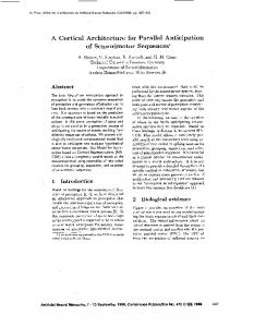
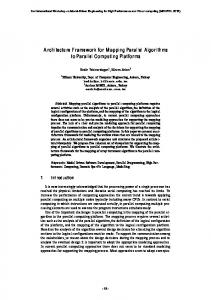
3.3. Calculation Reduction by Parallel Extraction In this section, we show, through simulations, the reduction effect of the amount of calculation by the parallel extraction. In the simulations, we count the number of moment extractions for all particles in an image. Moment extractions in all dimensions are defined as one set, so this number corresponds to the number of times targets are selected for the parallel extraction. The image size is 256 × 256 pixels. Image patterns are generated by randomly setting the size and positions of circles within a radius of 6 pixels. Figure 4 shows an example of the parallel extraction in which the pattern has 172 particles. In Fig.4, black particles are the targets for parallel extraction. We can see that all operations for moment extraction are finished after only 12 iterations by parallel extraction, compared to 172 iterations conventionally. Figure 5 shows the relationship between the number of objects and the number of extractions. The plotted points are simulation results and the curve is an approximated line to the plotted points. This curve is assumed to be an exponential function passing through the points (0, 0) and (1, 1). Also, the straight line shows the conventional case. When we define a as the number of targets and b as the number of extractions, the curve is b = a0.511 and the straight line is b = a. These results show that the parallel extraction enables a significant reduction in the amount of calculations. 3.4. Architecture Performance In this section, we evaluate the performance of the proposed architecture by considering a practical application. Here, we consider PIV as an example application. The following observation environment is assumed. The observed particles move at 10 m/s. The observed area is 200 × 200 mm2 . The resolution is 1024 × 1024 pixels in order to observe about 4000 particles, which have the average spaces of about 5 pixels, with a diameter of 10 pixels. The particles need to be observed at a frame rate of 10 kHz so that the motion of particles between Journal of Robotics and Mechatronics Vol.17 No.4, 2005
Parallel Extraction Architecture for Information of Numerous Particles in Real-Time Image Measurement
frames is within about 5 pixels. A vision system capable of imaging and transferring 352 × 288 pixel images at a frame rate of 10 kHz has previously been demonstrated [12]. Therefore, we assume that a suitable device for this PIV can be realized. We describe the moment extraction below. The circuits for moment extraction within the array connect elements as a binary tree. Each element consists of a one-bit full adder and a flip-flop. Images are binary and the size is 2n × 2n . The 0th moment calculation within the array needs (n + 1) clock cycles because the calculation is executed sequentially, one bit per cycle. On the other hand, as shown in Fig.2, the moments requiring multiplication by the x coordinate can be calculated from the results of each column outside the array. Therefore, the required calculation within the array is only for the y coordinate. For example, the moments from 0th to 2nd order, m00 , m01 , and m02 , need to be calculated within the array. The moments m10 and m20 can be calculated from m00 and m11 can be in turn calculated from m01 . The 1st moments and 2nd moments need (2n − 1) and (3n − 1) clock cycles, respectively. The total number of clock cycles is (6n − 1). The clock period is nt1 , where the summation delay per element is t1 , because it is determined by the time required for extracting the moment within the array. Also, as we mentioned in Section 3.1, the processing outside the array is assumed to be sufficiently fast. As a result, the total processing time for the 0th, 1st, and 2nd moments is nt1 (6n − 1). Next, we describe the selection processing. We estimate the total processing time as the sum of the 1st, 3rd, and 4th steps in the iterative operations explained in Section 3.2. The delay per pixel is defined as t2 , which equals the execution time for a single step at each equation. Also, all particles and concavities to be filled are assumed to be within objects of size A × A pixel2 and B × B pixel2 , respectively. Therefore, the total time can be approximated to t2 (2B2 + 2n + 2A). Based on the model described above, we now show the possibility of realizing real-time PIV. √ The number of moment extractions for a particles is a, based on the results of Section 3.3. We also set the parameters as follows: t1 = t2 = 1ns, A = 10, B = 3. Although the processing speed is the highest for the 1024 × 1024 parallel implementation, it can be implemented by other configurations. The conditions required for this application can also be fulfilled by a configuration in which we divide the entire input image into a number of blocks and process each block one by one. In this case, the suitable block size is 256 × 256 pixels. When n = 8, moment extraction from 0th to 2nd order takes 376 ns and the selection processing takes 284 ns. We estimate the total processing time using the longer time because these operations are done simultaneously. When each block √ has a particles, the total processing time is (16 × 376 × a)ns. The total number of particles in the entire image corresponds to 16a. Therefore, within 100 µ s, we can obtain the moments of 4096 particles. Journal of Robotics and Mechatronics Vol.17 No.4, 2005
Serial Interface RAM
Controller
RAM Control Signal
image
moment
Target Selection
Moment Extraction
External Processing
Fig. 6. System configuration.
This result shows that it is possible, with our proposed architecture, to realize real-time image measurement at high frame rate. In addition, in this processing model, the processing time can be further reduced because improvements and optimizations can be made to the moment extraction circuit, such as pipelining.
4. Implementation in FPGA We implemented the proposed architecture in FPGA by using a hardware description language, Verilog-HDL. Fig.6 shows the block diagram of the overall system, which consists of target selection, moment extraction, and external processing. Target selection and moment extraction were implemented as a parallel processor array. In this implementation, the array dealt with 32 × 32 pixel data in parallel. External processing was implemented outside the array. The target image for parallel extraction was generated from an input image thorough target selection. Moment extraction received the target image and outputted moments for each column. In the external processing part, the moments for the entire image were calculated. Data for checking operations such as input images and results passed through a serial port between the FPGA and a computer. The each processing part is detailed below. Figure 7 shows the array of target selection and its processing element. The circuit executes multiple operations by changing its configuration in synchronization with control signals. Steps in the algorithm in Section 3.2 are carried out sequentially. Therefore, we don’t need to implement multiple identical logic parts included in 5
Watanabe, Y. et al.
Fig. 7. Structure of selection element.
Fig. 8. Structure of moment extraction.
the steps for each. This is intended to reduce the required area. In the implemented circuits, each pixel element communicated asynchronously with its neighborhood, which enabled high-speed processing. Moment extraction for each column is shown in Fig.8. As mentioned in Section 3.4, we configured the circuit connecting elements as a binary tree. Each element consisted of a one-bit full adder and a flip-flop. The circuit received data from preprocessing elements and outputted the column moments, while selecting proper pixel data through the masking unit. Also, we implemented circuits for moment extraction outside the array as the same structure for the sake of simplicity, although the processing could be improved by other configurations. We obtained multiple results simultaneously by providing several moment extraction parts and a circuit dividing column data into the result of each target region. In this implementation, we provided the four parts. These circuits received data from column summation within the array and outputted the moments of targets. This implemented system outputted the 0th and 1st moments as particle information. The FPGA device used was the Virtex-II Pro series XC2VP50 made by Xilinx. XC2VP50 contained 53,169 logic cells. Also it had 232 RAM blocks, containing a total of 4176 kbits. The speed grade was -7 in this im6
plementation. As a result, it took 38% of all resources (slices) in XC2VP50 to implement the 32 × 32 array and the processing circuits outside the array. The clock frequency provided to the circuits was set to 100 MHz. This clock controlled summation operations. In this case, the summation delay per element was set to 2 ns. We confirmed that the implemented circuits selected the proper targets for parallel extraction and outputted correct moments for any pattern. This implementation using FPGA was intended to check operations. Thus, the placement of circuits on FPGA was not optimal in processing speed. We can improve clock frequency up to about 200 MHz by optimizing the configuration based on suitable timing constraints, which corresponds to a delay per element of 1 ns. This shows that FPGA has the possibility as a platform for our proposed architecture in processing speed. However, the array size in this implementation is not adequate for actual applications, which can be solved, for example, by using multiple FPGAs. We also consider implementing the architecture as ASIC. The required sizes of the processing element for selection processing and summation array are estimated roughly at 30 gates and 14 gates, respectively. These are based on logic synthesis targeting AMS 0.35 µ m CMOS process. International Technology Roadmap for Semiconductors 2004 (ITRS2004) reports that the usable degree of location for transistors in ASIC is 225 Mtransistors/cm2 in 2005. Assuming that the chip is 0.25 cm2 , we can implement the configuration described in this section as a 512 × 512 array system including 50 moment extraction parts outside the array. This shows that we can realizing the proposed architecture as a potential platform for real-time image measurement.
5. Conclusion We have proposed and designed a parallel extraction architecture for extracting information of numerous particles. We have also implemented it in FPGA and confirmed that it functions correctly. This architecture is capable of extracting a sufficient amount of information from images even when real-time processing at high frame rates is required. Such processing is very useful in various applications. As the next step, we will develop a system that connects a processor based on our architecture with a high-speed vision system. Also, we plan to demonstrate new applications using this real-time system, such as fluid and motion measurement based on PIV, precise microscope observation of numerous protozoa, image recognition for robot control, inspection, industrial applications, and so on. References: [1] [2] [3] [4]
http://www.micron.com/products/imaging/ http://www.dalsa.com/ http://www.fillfactory.com/ M. Raffel, C. E. Willert, and J. Kompenhans, “Particle Image Velocimetry: A Practical Guide (Experimental Fluid Mechanics),” Springer Verlag, 1998.
Journal of Robotics and Mechatronics Vol.17 No.4, 2005
Parallel Extraction Architecture for Information of Numerous Particles in Real-Time Image Measurement [5] M. K. Hu, “Visual Pattern Recognition by Moment Invariants,” IRA Transactions on Information Theory, Vol.IT-8, pp. 179-187, 1962. [6] I. Ishii, T. Komuro, and M. Ishikawa, “Method of Moment Calculation for a Digital Vision Chip System,” Proceedings of IEEE International Workshop on Computer Architecture for Machine Perception, pp. 41-48, 2000. [7] T. Komuro, S. Kagami, and M. Ishikawa, “A New Architecture of Programmable Digital Vision Chip,” Proceedings of 2002 Symposium on VLSI Circuits, pp. 266-269, 2002. [8] Y. Imai, A. Namiki, K. Hashimoto, and M. Ishikawa, “Dynamic Active Catching Using a High-speed Multifingered Hand and a High-speed Vision System,” Proceedings of 2004 IEEE International Conference on Robotics and Automation, pp. 1849-1854, 2004. [9] T. Senoo, A. Namiki, and M. Ishikawa, “High-Speed Batting Using a Multi-Jointed Manipulator,” Proceedings of 2004 IEEE International Conference on Robotics and Automation, pp. 1191-1196, 2004. [10] H. Oku, I. Ishii, and M. Ishikawa, “Tracking a Protozoon Using High-Speed Visual Feedback,” Proceedings of 1st Annual International IEEE-EMBS Special Topic Conference on Microtechnologies in Medicine & Biology, pp. 156-159, 2000. [11] N. Ogawa, H. Oku, K. Hashimoto, and M. Ishikawa, “Motile Cell Galvanotaxis Control using High-Speed Tracking System,” Proceedings of 2004 IEEE International Conference on Robotics and Automation, pp. 1646-1651, 2004. [12] S. Kleinfelder, S. Lim, X. Liu, and A. E. Gamal, “A 10000 Frames/s CMOS Digital Pixel Sensor,” IEEE Journal of Solid-State Circuits, Vol.36, No.12, pp. 2049-2058, 2001.
Name: Yoshihiro Watanabe
Affiliation: Doctor Course Student, Department of Information Physics and Computing, Graduate School of Information Science and Technology, University of Tokyo
Address: 7-3-1 Hongo, Bunkyo-ku, Tokyo 113-8656, Japan
Brief Biographical History: 2004 Received M.E. degree in Department of Information Physics and Computing from the University of Tokyo, Tokyo, Japan 2004- Doctor Course Student, Department of Information Physics and Computing, University of Tokyo 2004- Research Fellow of the Japan Society for the Promotion of Science
Main Works:
• “Real-time Visual Measurements using High-speed Vision,” Optics East 2004 / Machine Vision and its Optomechatronic Applications, Proceedings of SPIE, Vol.5603, pp. 234-242, 2004.
Membership in Learned Societies: • The Robotics Society of Japan (RSJ)
Name: Takashi Komuro
Affiliation: Research Associate, Department of Information Physics and Computing, Graduate School of Information Science and Technology, University of Tokyo
Address: 7-3-1 Hongo, Bunkyo-ku, Tokyo 113-8656, Japan
Brief Biographical History: 2001 Received Ph.D. degree in Mathematical Engineering and Information Physics from University of Tokyo, Tokyo, Japan 2001-2002 Research Fellow, Japan Science and Technology Corporation 2002- Research Associate, Department of Information Physics and Computing, University of Tokyo
Main Works:
• “Dynamically Reconfigurable SIMD Processor for a Vision Chip,” IEEE Journal of Solid-State Circuits, Vol.39, No.1, pp. 265-268, 2004. • “A Digital Vision Chip Specialized for High-speed Target Tracking,” IEEE transaction on Electron Devices, Vol.50, No.1, pp. 191-199, 2003. • “Device and System Development of General Purpose Digital Vision Chip,” Journal of Robotics and Mechatronics, Vol.12, No.5, pp. 515-520, 2000.
Membership in Learned Societies:
• The Robotics Society of Japan (RSJ) • The Society of Instrument and Control Engineers (SICE) • The Institute of Image Information and Television Engineers (ITE)
Journal of Robotics and Mechatronics Vol.17 No.4, 2005
7
Watanabe, Y. et al.
Name: Shingo Kagami
Affiliation: Research Associate, Department of Information Physics and Computing, Graduate School of Information Science and Technology, University of Tokyo
Address: 7-3-1 Hongo, Bunkyo-ku, Tokyo 113-8656, Japan
Brief Biographical History: 2003 Received Ph.D. degree in Mathematical Engineering and Information Physics from the University of Tokyo, Tokyo, Japan 2003 Research Fellow, Japan Science and Technology Corporation 2003- Research Associate, Department of Information Physics and Computing, University of Tokyo
Main Works:
• “A Sensor Selection Method Considering Communication Delays,” Proc. IEEE Int. Conf. Robotics and Automation, pp. 206-211, Apr. 2004.
Membership in Learned Societies:
• The Robotics Society of Japan (RSJ) • The Institute of Image Information and Television Engineers (ITE)
Name: Masatoshi Ishikawa
Affiliation: Professor, Department of Information Physics and Computing, Graduate School of Information Science and Technology, University of Tokyo
Address: 7-3-1 Hongo, Bunkyo-ku, Tokyo 113-8656, Japan
Brief Biographical History: 1979- Senior Researcher, Industrial Products Institute 1989- Associate Professor, University of Tokyo 1999- Professor, University of Tokyo
Main Works:
• “A CMOS Vision Chip with SIMD Processing Element Array for 1ms Image Processing,” Proc. IEEE Int. Solid-State Circuits Conference (ISSCC’99), pp. 206-207, Feb. 1999.
Membership in Learned Societies:
• The Robotics Society of Japan (RSJ) • The Society of Instrument and Control Engineers (SICE) • The Institute of Electronics, Information and Communication Engineers (IEICE)
8
Journal of Robotics and Mechatronics Vol.17 No.4, 2005