Parallel Independence of Amalgamated Graph Transformations Applied to Model Transformation Hartmut Ehrig1 , Ulrike Golas1 , Gabriele Taentzer2 , Claudia Ermel1 , and Enrico Biermann1 1
Institut f¨ ur Softwaretechnik und Theoretische Informatik Technische Universit¨ at Berlin, Germany {ehrig,ugolas,lieske,enrico}@cs.tu-berlin.de 2
Fachbereich Mathematik und Informatik Philipps-Universit¨ at Marburg, Germany
[email protected]
Abstract. The theory of algebraic graph transformation has proven to be a suitable underlying formal framework to reason about the behavior of model transformations. In order to model an arbitrary number of actions at different places in the same model, the concept of amalgamated graph transformation has been proposed. Rule applications of certain regularity are described by a rule scheme which contains multirules modeling elementary actions and a common kernel rule for their synchronization (amalgamation). The amalgamation theorem by B¨ ohm et al. ensures that for two multi-rules, the application of the amalgamated rule yields the same result as two iterative rule applications, respecting their common kernel rule application. In this paper, we propose an extension of the amalgamation theorem to an arbitrary finite number of synchronous rule applications. The theorem is used to show parallel independence of amalgamated graph transformations by analyzing the underlying multi-rules. As example, we specify an excerpt of a model transformation from Business Process Models (BPM) to the Business Process Execution Language (BPEL).
1
Introduction
Model transformation is one of the key activities in model-driven software development. The theory of algebraic graph transformation has proven to be a suitable underlying formal framework to reason about the behavior of model transformations, e.g. showing termination and confluence [1]. Although graph transformation is an expressive, graphical and formal means to describe computations on graphs, single rules are not always sufficient to express complex actions. In that case, a specification of either sequential or parallel rule application is needed to define a potentially infinite set of rule apllications in a finite way. Often, the problem arises to model an arbitrary
number of similar parallel actions at different places in the same model. One way to transform multiple recurring structures (multi-object structures) is the sequential application of rules by explicitly encoding an iteration over all the actions to be performed. Often, this solution is not as declarative as it could be, since we have to care about the stepwise execution of a forall operation on a collection. Hence, we propose the use of amalgamated graph transformation concepts, based on parallel graph transformation introduced in [2] and extended to synchronized transformations in [3,4], to define model transformations with multiobject structures. The essence of amalgamated graph transformation is that (possibly infinite) sets of rules with some regularity can be described by a finite set of multi-rules modeling the elementary actions, amalgamated at a kernel rule. The synchronization of rules along kernel rules in so-called interaction schemes allows a transformation step to be maximally parallel in the following sense: An amalgamated rule, induced by an interaction scheme, is constructed by a number of multi-rules being synchronized at the kernel rule. The number of multi-rules is determined by the number of different multi-rule matches found such that they all overlap in the match of the kernel rule. Hence, the transformation of multi-object structures can be described in a general way though the number of actually occurring objects in the instance model is variable. The amalgamation theorem by B¨ohm et al.[3] ensures that for two instances of a multi-rule the application of the amalgamated rule yields the same result as the iterative application of these two rules, where their common kernel is transformed only once. In this paper, we propose an extension of the amalgamation theorem to an arbitrary finite number of multi-rules. Using this extension, the transformation of models with variably many multi-object structures can be handled in a general way. An additional result allows to analyze parallel independence of amalgamated graph transformations by analysing the underlying multi-rules. The concept of amalgamation is useful for several kinds of model transformation between visual models. In this paper, we present the theoretical results without proofs, while the theory with proofs is presented in the categorical framework of weak adhesive HLR categories in [5]. The main aim of this paper is to show how amalgamated graph transformation can be applied to model transformation. For this purpose, the theoretical results are applied to a model transformation translating simple business process models written in the Business Process Modeling Notation (BPMN) to executable processes formulated in the Business Process Execution Language for Web Services (BPEL). BPMN models allow to split the control flow in an arbitrary number of branches which are rejoined later. An analogous transformation step is the translation of fork-join structures. We use this excerpt of the model translation to motivate our amalgamation concept. The independence result of this paper can be used to check if several applications of these amalgamated transformation steps are independent of each other and can be executed in parallel. 2
We assume that the reader is familiar with the basic concepts of algebraic graph transformation and basic constructions like pushouts and pullbacks which are used in Sections 3 and 4. For an introduction to these concepts we refer to [1]. The paper is structured as follows: In the next section, our running example, an excerpt of a model transformation from BPMN to BPEL, is introduced. Amalgamated graph transformation is reviewed in Section 3 where also the new extended amalgamation theorem is presented. This theorem is used in Section 4 to show parallel independence of amalgamated graph transformations. Finally, Section 5 considers related approaches (including tool-based approaches) and Section 6 concludes the paper.
2
Example: Model Transformation from BPMN to BPEL by Amalgamated Graph Transformation
In this section, we describe our running example, an excerpt of a model transformation from the Business Process Modeling Notation (BPMN) to the Business Process Execution Language for Web Services (BPEL) according to the translation by Van der Aalst et al. in [6]. BPMN is a standard notation for modeling business processes used for business analysis. In addition, BPEL is introduced as a notation to define executable processes, i.e. processes that can be loaded into an execution engine which will then coordinate the activities specified in the process definitions. Since both languages are quite complex, we will consider subsets of the BPMN and BPEL notations only. In addition, we use a reference structure to connect BPMN elements with their newly constructed BPEL counterparts. During the transformation, the BPMN is modified as well because structures are collapsed (similiar to parsing) while being transformed to BPEL. In this paper, we concentrate on the translation of BPMN And and Xor constructs to the corresponding BPEL language elements Flow and Switch via amalgamated graph transformations. Translating those constructs with ordinary graph transformation rules would require a complex control structure for guiding the rule application process. Other BPMN language constructs like While or Repeat can be handled by normal graph transformation rules. The complete model transformation case study is described in [7] from a practical point of view. The model transformation is implemented using AGG [8], a development environment for attributed graph transformation systems supporting the algebraic approach to graph transformation [1]. AGG has been extended recently by support for defining and applying amalgamated graph transformation. All screenshots in this paper are taken from the AGG editors for rules and interaction schemes. 2.1
Type graphs
We define type graphs of the source language BPMN and the target language BPEL. Furthermore, in order to define transformation rules, relations between 3
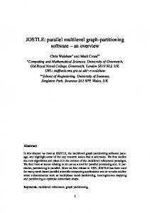
source and target meta-models are given by reference nodes of type F2ARef. The type graph integrating the BPMN source model (left-hand part), the reference part (the node type F2ARef and its adjacent edge types bpmn and bpel) and the target model (right-hand part) is shown in Fig. 1.
Fig. 1. BPMN2BPEL type graph
For the BPEL type graph, the parent-child relation on activities has been modeled as a child relation. This leads to a structure similar to the XML representation of the BPEL language in [6]. 2.2
A BPMN instance graph: ATM machine
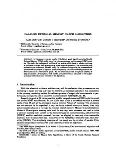
As an example we consider a BPMN diagram which models a person’s interaction with an ATM (see Fig. 2 where the concrete and abstract syntax of the diagram are depicted). In the upper part, the ATM machine accepts and holds the card of the person while simultaneously contacting the bank for the account information. (The language elements AndSplit and AndJoin are used to model parallel actions.) Afterwards, the display prompts the user for the PIN. Depending on the user’s input there are three possible outcomes: – the user enters the correct PIN and can withdraw money, – the user enters the wrong PIN (a message is displayed), – the user aborts the operation (an alarm signal is given). For modelling alternative actions, the language elements XOrSplit and XOrJoin are used. Any further interaction with the ATM (like returning the card to the user) is not modelled here. Next nodes without conditions have an empty string as ”cond ” attribute. For simplicity, in Fig. 2 (b), these Next nodes are shown without their attributes. In the following, we will use the abstract syntax only where the source BPMN model like the ATM machine in Fig. 2, the corresponding target BPEL model and all intermediate models of the model transformation are typed over the type graph in Fig. 1. 4
Fig. 2. ATM machine in BPMN in concrete syntax (a) and abstract syntax (b)
2.3
Transformation rules
Basically, the transformation from BPMN to BPEL is modelled in two phases: 1. translate all simple activities from BPMN to BPEL, 2. collapse all complex structures to new activities in the source model while creating the corresponding structure in the target model, e.g. sequences, switch or flow structures. Rule CreateSimpleActivity in Fig. 3 models the translation of a simple activity from BPMN to BPEL. Note that the negative application condition (NAC) takes care that a corresponding BPEL SimpleActivity is created only if its BPMN Activity has not already been translated before. Similar rules model the translation of Alarm and Message events which are changed to an activity with a corresponding SimpleActivity as translation. This eases the succeeding steps of the translation, because these events are handled like activities in BPEL. While translating structures from BPMN to BPEL, reference nodes are created connecting source model flow objects to BPEL activities in the target model. The translation of a chain of BPMN activities is done by two rules shown in Figs. 4 and 5: Rule CreateSequence creates a new sequence in the BPEL model and inserts the first two activities into this sequence. Rule CreateSequence2 deals with the case that the sequence has already been created in the BPEL model. Then, the current activity is added to the existing sequence. The negative application condition (NAC) of each rule ensures that activities in a sequence are 5
Fig. 3. Rule CreateSimpleActivity
translated from top to bottom, i.e. there are no other untranslated activities in the sequence above the current ones, and that the order from the BPMN structure is preserved in the BPEL model. Note that we do not show all NACs in the figures, but only a representative.
Fig. 4. Rule CreateSequence
Fig. 5. Rule CreateSequence2
6
In Fig. 6, the result after applying rules CreateSimpleActivity and CreateSequence as long as possible to the BPMN model in Fig. 2 is shown where all activities and (simple) sequences are translated into the corresponding BPEL objects. The next step is to translate the And and Xor constructs.
Fig. 6. Intermediate result of the model transformation
An And construct (a number of branches surrounded by an AndSplit and AndJoin element) is translated to a Flow container node which contains a child for each branch emerging from the AndSplit. Since the number of branches can be arbitrary, a normal graph transformation rule or any finite number of rules would not be sufficient to express this situation. Therefore, we use amalgamated graph transformation to express maximal parallel execution in the following sense: A common subaction is modelled by the application of a common kernel rule of all additional actions (modelled by multi-rules). For example, in order to process an And construct, the common subaction processes one branch only. Independent of the number of additional branches, this is the kernel action which will always happen. Hence, we model this action by the kernel rule in the upper part of Fig. 7 where one branch surrounded by an AndSplit and AndJoin is translated to 7
a BPEL Flow node with one child. The NAC takes care that there are no other branches with sequences of activities within the And construct (i.e. sequences should be collapsed into single activities before translating the And construct).
Fig. 7. Interaction scheme CreateFlow
Additional subactions now are modelled by multi-rules. Each multi-rule contains at least the kernel rule and specifies an additional action which is executed as many times as matches for this additional part can be found in the host graph. The multi-rule for processing And constructs is shown in the bottom part of Fig. 7. It extends the kernel rule by one more branch. Formally, the synchronization possibilities of kernel and multi-rules are defined by an interaction scheme consisting of a kernel rule and a set of rules called multi-rules such that the kernel rule is embedded in each of the multi-rules. The kernel morphism from the kernel rule to the multi-rule is indicated in Fig. 7 by single node mappings shown by corresponding numbers of some of the graph objects. Note that all missing node and edge mappings can be uniquely determined from the given ones. The application of an interaction scheme, i.e. of multi-rules synchronized at their kernel rule is twofold: At first, a match of the kernel rule is selected. Then, 8
multi-rule instances are constructed, one for each new match of a multi-rule in the current host graph such that it overlaps with the kernel match only. Then, all multi-rule instances are glued at their corresponding kernel rule objects which leads to a new rule, the amalgamated rule. The application of the amalgamated rule at the amalgamated match consisting of all multi-rule matches glued at the kernel match is called amalgamated graph transformation. For the handling of Xor constructs (a number of branches surrounded by an XorSplit and an XorJoin element), we have an analogous interaction scheme CreateSwitch which also consists of a kernel rule processing one branch, and one multi-rule taking care of additional branches (see Fig. 8). Here, a BPEL Switch node with corresponding children is created, where the condition in the Next node is translated to a Case distinction.
Fig. 8. Interaction scheme CreateSwitch
The application of the CreateSwitch interaction scheme to the Xor construct depicted in the bottom part of Fig. 6 yields an amalgamated rule where the kernel rule is glued with two instances of the multi-rule (since we have three branches between the XorSplit and the XorJoin). The amalgamated rule (shown in Fig. 9) is then used to process the three branches in one step by applying it to the graph in Fig. 6. The NAC shown in Fig. 9 originates from the kernel rule and is simply copied from it. NACs of multi9
rules would require shifting to preserve their meaning as is explained in [5]. After the application of the amalgamated rule, the rule DeleteXor in Fig. 10 removes the XorSplit and XorJoin which are only connected by a single branch with a single acitivity after the application of the amalgamated rule. A similar rule DeleteAnd removes the AndSplit and AndJoin after the successful Flow construction.
Fig. 9. Amalgamated rule of CreateSwitch for the ATM model
Fig. 10. Rule DeleteXor
If we apply our transformation rules in a suitable order starting with the BPMN model ATM in Fig. 2, we get the resulting integrated graph shown in Fig. 11 (b). Here, some elements of the BPMN notation still exist, comprising a sort of stop graph of the parsing process because no transformation rule can be applied anymore. If a pure BPEL graph is desired, this remaining BPMN structure can be deleted by an additional rule. The abstract syntax of the BPEL expression is the tree with root node Sequence which is the target of the bpel edge 10
from the F2ARef node. The XML syntax of the BPEL model corresponding to this tree is shown in Fig. 11 (a).
Fig. 11. ATM machine as transformation result in concrete BPEL syntax (a) and in abstract syntax (b)
3
Amalgamated Graph Transformation
In this section, we give the formal foundations of amalgamated graph transformation based on graph transformation in the well-known double-pushout approach. We assume the reader to be familiar with this approach (see [1] for an introduction and a large number of theoretical results). We concentrate on the presentation of new concepts and results. The formal proofs of our results can be found in [5]. For simplicity, we present the theory without negative application conditions and without attributes, but it has been extended already to this more general case which is used in our example. In fact, the theory in [5] is presented in the categorical framework of weak adhesive HLR categories [1] for rules with nested application conditions in the sense of Habel-Pennemann [9] where negative application conditions are a special case. Formally, a kernel morphism describes how the kernel rule is embedded into a multi-rule. We need some more technical preconditions to make sure that the embeddings of the L-, K-, and R-components are consistent. l
r
0 0 Definition 1 (Kernel Morphism). Given rules p0 = (L0 ←− K0 −→ R0 )
l
r
1 1 and p1 = (L1 ←− K1 −→ R1 ) with injective morphisms li , ri f or i ∈ {0, 1}, a kernel morphism s : p0 → p1 , s = (sL , sK , sR ) consists of injective morphisms sL : L0 → L1 , sK : K0 → K1 , and sR : R0 → R1 such that in the following
11
diagram (1) and (2) are pullbacks, and (1) has a pushout complement for sL ◦ l0 . p0 is then called kernel rule and p1 multi-rule. p 0 : L0 s
sL
p 1 : L1
l0
(1) l1
K0 sK
K1
r0
(2) r1
R0 sR
R1
Example 1. The kernel rule and the multi-rule of CreateFlow in Fig. 7 are linked by a kernel morphism, which is indicated in Fig. 12 by equal numbering of selected elements. The mapping of all remaining elements can be induced uniquely. Fig. 12 shows that we have pullbacks (1) and (2). A pullback of two injective graph morphisms can be considered as intersection of two graphs embedded in a common graph. E.g. pullback (1) models the intersection K0 of L0 and K1 in L1 . Morphisms sL and l1 indicate how K0 and L0 are embedded in L1 . The pushout complement for sL ◦ l0 adds the graph part which is needed to complete L0 over K0 such that L1 is the result. Note that the pushout complement is not the graph K1 in Fig. 12, but looks like the left-hand side of the rule in Fig. 13.
Fig. 12. Kernel morphism of interaction scheme CreateFlow
For a given kernel morphism, the complement rule is the remainder of the multi-rule after the application of the kernel rule, i.e. it describes what the multi12
rule does in addition to the kernel rule. The following lemma is an important construction which is used in Theorem 1. r
l
0 0 R0 ) and K0 −→ Lemma 1 (Complement Rule). Given rules p0 = (L0 ←−
l
r
1 1 p1 = (L1 ←− K1 −→ R1 ) and a kernel morphism s : p0 → p1 then there exists a
l
r
p
1 complement rule p1 = (L ←− K −→ R) such that each transformation G ==⇒ H p0 0 p1 can be decomposed into a transformation sequence G ==⇒ G ==⇒ H.
Proof Idea: Intuitively, the complement rule is the smallest rule that extends K0 such that it creates and deletes all these parts handles by the multi but not by the kernel rule. Example 2. For the kernel rule and the multi-rule of CreateFlow in Fig. 7, the complement rule is shown in Fig. 13. It handles the transformation of the additional branch which has to be added as an activity to the already existing flow.
Fig. 13. Complement rule of CreateFlow
According to Fact 1, each transformation by the multi-rule of CreateFlow (Fig. 7) applied to the graph in Fig. 6 can be decomposed into a transformation sequence applying first the kernel rule of CreateFlow (Fig. 7) to the graph in Fig. 6 and then the complement rule of CreateFlow in Fig. 13 to the resulting graph. A bundle of kernel morphisms over a common kernel rule forms an interaction scheme. l
r
i i Definition 2 (Interaction Scheme). Given rules pi = (Li ←− Ki −→ Ri ) for i = 0, . . . , n, an interaction scheme is a bundle of kernel morphisms s = (si : p0 → pi )i=1,...,n .
13
Given an interaction scheme which describes the basic actions in its kernel rule and a set of multi-rules, we need to construct a graph-specific interaction scheme for a given graph and kernel match. This specific interaction scheme contains a certain number of multi-rule copies for each multi-rule of the basic scheme. To do so, we search all different multi-rule matches which overlap in the kernel match. The number of different multi-rule matches determines how many copies are included in the graph-specific interaction scheme which is the starting point for the amalgamated rule construction defined in Def. 3. Consider Fig. 14 as an example. The basic interaction scheme is given on the left. It consists of kernel rule r0 which adds a loop. Moreover, it contains one multi-rule r1 modeling that object 2 being connected to object 1 is deleted and a new object is created and connected to object 1 which has a loop now. Note that there is a bundle of kernel morphisms which embed the kernel rule into the multi-rules. Given graph G, there are obviously three different matches from multi-rule r1 to G which overlap in the match of the kernel rule to G. Hence, the multi-rule can be applied three times. Thus, we need three copies of the multirule in the graph-specific interaction scheme, all with kernel morphisms from kernel rule r0 . In our example, the graph-specific interaction scheme is shown on the right. Gluing all multi-rules in the graph-specific interaction scheme at their common kernel rule, we get the amalgamated rule with respect to G, shown at the bottom of Fig. 14. In the following definition, we clarify the construction of amalgamated rules from interaction schemes which are intended to be graph-specific already. l
r
i i Definition 3 (Amalgamated Rule). Given rules pi = (Li ←− Ki −→ Ri ) for i = 0, . . . , n and an interaction scheme s = (si : p0 → pi )i=1,...,n , then the ˜ l r˜ ˜ ←− ˜ −→ ˜ is constructed componentwise over si amalgamated rule p˜s = (L K R) as stepwise pushouts over i.
p0 : L0 si si,L
pi : Li ti
ti,L
˜ p˜s : L
l0
(1) li
(3) ˜ l
K0 si,K
Ki ti,K
˜ K
r0
(2) ri
(4) r˜
R0 si,R
Ri ti,R
˜ R
Remark 1. We sketch the idea how to construct the componentwise pushout for n = 3 for the L-component: 1. Construct the pushout (1a) of s1,L and s2,L . 2. Construct the pushout (1b) of s1 ◦ s1,L and s3,L . ˜ for the amalgamated rule. 3. L3 is the resulting left-hand side L 14
Fig. 14. Construction of an amalgamated rule
L0 s2,L
L2
s1,L
(1a) s2
L1
L0
s1 s3,L
L2
L3
s1 ◦s1,L
L2
(1b) L3
This construction is unique, independent of the order of i, and can be done similarly for the K- and R-components. By pushout properties (see [1]), we obtain unique morphisms ˜l and r˜. Example 3. In our example transformation for the ATM machine from BPMN in Fig. 2 to BPEL in Fig. 11 we can use two different amalgamated rules - one for the transformation of the And construct and one for the Xor construct. For the And construct, the multi-rule in Fig. 7 is applied once which means that n = 1 and the amalgamated rule is isomorphic to the multi-rule itself. For the Xor construct, the same multi-rule is applied twice, leading to the amalgamated rule shown in Fig. 9. The application of an amalgamated rule to a graph G is called an amalgamated transformation. Since an amalgamated rule is a normal transformation rule, an amalgamated graph transformation step at an amalgamated rule and an amalgamated match is a normal graph transformation step. If we have a bundle 15
of direct transformations of a graph G, where for each transformation one of the multi-rules is applied, we want to analyse if the amalgamated rule is applicable to G combining all the single transformation steps. These transformations are compatible, i.e. multi-amalgamable, if the matches agree on the kernel rules, and are independent outside. Definition 4 (Multi-Amalgamable). Given an interaction scheme s = (si : p ,mi Gi )i=1,...n p0 → pi )i=1,...,n , a bundle of direct transformations steps (G ==i==⇒ is multi-amalgamable over s, if – it has consistent matches, i.e. mi ◦si,L = mj ◦sj,L =: m0 for all i, j = 1, . . . , n and – it has weakly independent matches, i.e. mi (Li )∩mj (Lj ) ⊆ m0 (L0 )∪(mi (li (Ki ))∩ mj (lj (Kj ))) for all 1 ≤ i 6= j ≤ n which means that the elements in the intersection of the matches mi and mj are either preserved by both transformations, or are also matched by m0 . L0 sj,L
si,L
Ki
li
Li
Lj
m0 mi
lj
Kj
mj
G Remark 2. The concepts of consistent matches and weakly independent matches have been used already for the case n = 2 in [3]. If a bundle of direct transformations of a graph G is multi-amalgamable, then we can apply the amalgamated rule directly to G leading to a parallel execution of all the changes done by the single transformation steps. Theorem 1 (Multi-Amalgamation). Given a bundle of multi-amalgamable p ,mi transformations (G ==i==⇒ Gi )i=1,...,n over an interaction scheme s then there is p˜ ,m ˜ qi an amalgamated transformation G ==s==⇒ H and transformations Gi ==⇒ H over pi ,mi qi p˜s ,m ˜ some rule qi such that G ====⇒ Gi ==⇒ H is a decomposition of G ====⇒ H. Note that qi is the complement rule of the kernel morphism ti : pi → p˜s and can be constructed as a gluing of the complement rules p1 , . . . , pn of p1 , . . . , pn over K0 . Gi qi
pi ,mi
G
p˜s ,m ˜
H
Proof Idea: Basically, p˜s is applicable to G because the bundle is multiamalgamable. Then we can apply Lemma 1 which implies the decomposition. 16
Example 4. The multi-rule of the interaction scheme CreateSwitch (Fig. 8) can be applied two times to the graph in Fig. 6 with the same kernel rule match (Fig. 8). In fact, the interaction scheme CreateSwitch leads to multi-amalgamable p ,mi Gi , i = 1, 2. By Theorem 1, we can apply the amaltransformations G ==i==⇒ p˜ ,m ˜ gamated rule (Fig. 9) to the same graph G, leading to G ==s==⇒ H, and for qi pi ,mi G ====⇒ Gi we have Gi ==⇒ H with q1 = p2 and q2 = p1 where p1 and p2 are the complement rules of p1 and p2 , respectively.
4
Parallel Independence of Amalgamated Graph Transformations
In this section, we want to analyze when two amalgamated graph transformations of a graph are parallel independent which means that they can be sequentially applied in any order. Of course, we could check parallel independence of the two transformations directly based on the definition and using the amalgamated rules. But even if we only know the underlying bundles of transformation steps via the multi-rules, we can analyze parallel independence of the amalgamated transformations based on these single transformation steps. Theorem 2 (Parallel Independence). Given two interaction schemes s and p ,mi s0 and two bundles of multi-amalgamable transformations (G ==i==⇒ Gi )i=1,...,n p0 ,m0
p ,m
p0 ,m0
j j i over s and (G ==j==⇒ G0j )j=1,...,n0 over s0 such that G ==i==⇒ Gi and G ==j==⇒ G0j are parallel independent for all pairs i, j. Then also the corresponding amal-
˜0 p˜ 0 ,m
p˜ ,m ˜
gamated transformations G ==s==⇒ H and G ==s===⇒ H 0 are parallel independent. Proof Idea: For parallel independence, there have to exist morphisms from the gluing objects of the one rule to the result of the second transformation and vice versa. If these morphisms exist for the single transformation steps, we can combine them to morphisms from the gluing objects of the amalgamated rules to the resulting objects of the amalgamated transformations. Moreover, the Local Church–Rosser Theorem leads to an object X with amalp˜ 0 ,n˜0
p˜ ,˜ n
gamated transformations H ==s==⇒ X and H 0 ==s=⇒ X. H qi
p˜s ,m ˜
p˜s0 ,n˜0
Gi pi ,mi
G
X
p0j ,m0j
G0j ˜0 p˜s0 ,m
qj0
H0
17
p˜s ,˜ n
Example 5. In the intermediate model in Fig. 6, we find a match for the kernel rule of CreateFlow (Fig. 7) using the left branch of the And construct, and an extension of this match for the multi-rule of CreateFlow covering also the right branch. This means that we get a bundle consisting of one transformation with the multi-rule of CreateFlow. Similarly, we can find a match for the kernel rule of CreateSwitch (Fig. 8) using the left branch of the Xor construct which can be extended to two different matches of the corresponding multi-rule, one using the middle branch and one using the right branch. This leads to a bundle consisting of two transformations with two instances of the multi-rule of CreateSwitch. If we apply all these multi-rules via the above defined matches, we obtain a p1 H1 handling the transformation of the And construct, and transformation G ==⇒ p0
p0
1 2 two transformations G ==⇒ H10 and G ==⇒ H20 handling the transformation of the left and middle resp. left and right branches of the Xor construct. For the first transformation, the multi-rule is isomorphic to the amalgamated rule because we have n = 1. Moreover, the last two transformations are multi-amalgamable because they agree on the kernel rule match and the matches are disjoint outside the kernel. This means that we can apply the amalgamated rule of CreateSwitch which is depicted in Fig. 9, directly to the graph in Fig. 6 transforming the complete Xor construct. The used matches of p1 and p01 as well as of p1 and p02 are disjoint which means that the corresponding transformations are parallel independent. Therefore we can apply Theorem 2 to these amalgamated transformations which means that the amalgamated transformations of the And and the Xor constructs are parallel independent and can be applied in any order to G leading to the same result X.
5
Related Work
There are several graph transformation-based approaches which realize the transformation of multi-object structures. PROGRES [10] and Fujaba [11] feature socalled set-valued nodes which can be duplicated as often as necessary. These two approaches handle multi-objects in a pragmatic way. Object nodes are indicated to be matched optionally once, arbitrarily often, or at least once. Object nodes that are not indicated as mulit-objects are matched exactly once. Adjacent arcs are treated accordingly. These two approaches are more restricted than ours, since they focus on multiple instances of single nodes instead of graph parts. Furthermore, PROGRES allows to embed the right-hand side of a rule in a flexible way by specifying an embedding clause. This clause considers the embedding of the corresponding left-hand side and declares for each type of arc running between the left-hand side and the context graph how it is replaced by an arc between the right-hand side and the context graph. Such an embedding clause cannot be defined in our approach. Instead we have to specify a multi-rule for each arc type used in the embedding clause. Since the context graph can be an arbitrary one, so can be the embedding. This is reflected by constructing an amalgamated rule suitable for the actual context and embedding. 18
Further approaches that realize amalgamated graph transformation are AToM3 , GReAT and GROOVE. AToM3 supports the explicit definition of interaction schemes in different rule editors [12] whereas GROOVE implements rule amalgamation based on nested graph predicates [13]. The GReAT tool can use a group operator to apply delete, move or copy operations to each match of a rule [14]. A related conceptual approach aiming at transforming collections of similar subgraphs is presented in [15]. The main conceptual difference to our approach is that we amalgamate rule instances whereas Grønmo et al. replace all collection operators (multi-objects) in a rule by the mapped number of collection match copies. Similarly, Hoffmann et al. define a cloning operator in [16] where cloned nodes roughly correspond to multi-objects. None of the aforementioned approaches so far investigate the formal analysis of amalgamated graph transformation. Here, to the best of our knowledge the amalgamation theorem in [3] has been the only formal result up to now. In this paper, we extend the amalgamation theorem to an arbitrary finite number of multi-rules. We implemented our amalgamation approach in AGG (also used for modeling the sample model transformation in this paper), and in our EMF transformation tool EMF Henshin [7,17]. Here, graph transformation concepts are transferred to model transformations in the Eclipse Modeling Framework (EMF).
6
Conclusions and Future Work
In this paper, we recall the concept of amalgamated graph transformations from [3], extend it to multi-amalgamation and apply it to model transformation. In fact, the amalgamation concept is very useful for this application area, because it allows to define graph transformation systems more compactly. Parallel actions which shall be performed on a set of similar object structures can be described by interaction schemes. An amalgamated graph transformation applies an interaction scheme, i.e. a set of parallel actions with the kernel rule as synchronization point, to a specific graph as one atomic step. Although amalgamated graph transformations are useful for specifying model transformations more naturally and more efficiently, the theory is not fully developed and thus, cannot be used to verify model transformations yet. Our paper can be considered as an essential contribution towards a theory of amalgamated graph transformations. Due to the multi-amalgamation theorem, the central technical result in this paper, we are able to characterize parallel independent amalgamated graph transformations. If we can show that two alternative steps in a model transformation sequence are parallel independent, we can apply them in any order. This result on parallel independence is essential to show confluence results for amalgamated graph transformations in future work. In [5], the theory of amalgamated graph transformation is formulated already in the framework of weak adhesive HLR categories such that it can be applied to typed attributed graph transformations with suitable application conditions. Moreover 19
it is intended to extend the amalgamation concept to triple graph grammars [18], which are well-known for the specification of model transformations.
References 1. Ehrig, H., Ehrig, K., Prange, U., Taentzer, G.: Fundamentals of Algebraic Graph Transformation. EATCS Monographs in Theor. Comp. Science. Springer (2006) 2. Ehrig, H., Kreowski, H.J.: Parallel graph grammars. In Lindenmayer, A., Rozenberg, G., eds.: Automata, Languages, Development. Amsterdam: North Holland (1976) 425–447 3. B¨ ohm, P., Fonio, H.R., Habel, A.: Amalgamation of graph transformations: a synchronization mechanism. Computer and System Sciences (JCSS) 34 (1987) 377–408 4. Taentzer, G.: Parallel and Distributed Graph Transformation: Formal Description and Application to Communication-Based Systems. PhD thesis, TU Berlin (1996) Shaker Verlag. 5. Golas, U.: Multi-Amalgamation in M-Adhesive Categories. Technical Report 2010/05, Technische Universit¨ at Berlin (2010) 6. Ouyang, C., Dumas, M., ter Hofstede, A.H.M., van der Aalst, W.M.P.: From BPMN process models to BPEL web services. In: IEEE International Conference on Web Services (ICWS 2006), 18-22 September 2006, Chicago, Illinois, USA, IEEE Computer Society (2006) 285–292 7. Biermann, E., Ermel, C.: Transforming BPMN to BPEL with EMF Tiger. In: Proc. Graph-based Tools (GraBaTs’09). (2009) 8. TFS-Group, TU Berlin: AGG. (2009) http://tfs.cs.tu-berlin.de/agg. 9. Habel, A., Pennemann, K.H.: Correctness of high-level transformation systems relative to nested conditions. Mathematical Structures in Computer Science 19 (2009) 1–52 10. Sch¨ urr, A., Winter, A., Z¨ undorf, A.: The PROGRES-approach: Language and environment. In Ehrig, H., Engels, G., Kreowski, H.J., Rozenberg, G., eds.: Handbook of Graph Grammars and Computing by Graph Transformation, Volume 2: Applications, Languages and Tools. World Scientific, River Edge, NJ, USA (1999) 487 – 550 11. Fischer, T., Niere, J., Torunski, L., Z¨ undorf, A.: Story diagrams: A new graph rewrite language based on the Unified Modeling Language. In Engels, G., Rozenberg, G., eds.: Proc. of the 6th International Workshop on Theory and Application of Graph Transformation (TAGT). Volume 1764 of LNCS. Springer, Berlin (2000) 296–309 12. de Lara, J., Ermel, C., Taentzer, G., Ehrig, K.: Parallel graph transformation for model simulation applied to timed transition Petri nets. ENTCS 109 (2004) 17–29 13. Rensink, A., Kuperus, J.H.: Repotting the geraniums: On nested graph transformation rules. ECEASST 18 (2009) 14. Balasubramanian, D., Narayanan, A., Neema, S., Shi, F., Thibodeaux, R., Karsai, G.: A subgraph operator for graph transformation languages. ECEASST 6 (2007) 15. Grønmo, R., Krogdahl, S., Møller-Pedersen, B.: A collection operator for graph transformation. In Paige, R., ed.: Proceedings of the International Conference on Theory and Practice of Model Transformations (ICMT’09). Volume 5563 of LNCS., Springer (2009) 67–82
20
16. Hoffmann, B., Janssens, D., van Eetvelde, N.: Cloning and expanding graph transformation rules for refactoring. In: Int. Workshop on Graph and Model Transformation (GraMoT’05). Volume 152 of Electr. Notes on Theor. Comput. Sci., Elsevier (2006) 53–67 17. Biermann, E., Ermel, C., Taentzer, G.: Lifting parallel graph transformation concepts to model transformation based on the Eclipse modeling framework. ECEASST 26 (2010) http://journal.ub.tu-berlin.de/index.php/eceasst/issue/view/36. 18. Sch¨ urr, A.: Specification of Graph Translators with Triple Graph Grammars. In Tinhofer, G., ed.: WG94 20th Int. Workshop on Graph-Theoretic Concepts in Computer Science. Volume 903 of Lecture Notes in Computer Science., Heidelberg, Springer Verlag (1994) 151–163
21