Oct 2, 2017 - Yin, Joseph Teran, Stanley Osher. University of California Los Angeles. Abstract. We present a parallel method for solving the eikonal equation ...
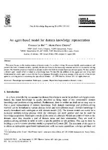
Parallel redistancing using the Hopf-Lax formula Michael Royston, Andre Pradhana, Byungjoon Lee, Yat Tin Chow, Wotao Yin, Joseph Teran, Stanley Osher University of California Los Angeles
Abstract We present a parallel method for solving the eikonal equation associated with level set redistancing. Fast marching [1, 2] and fast sweeping [3] are the most popular redistancing methods due to their efficiency and relative simplicity. However, these methods require propagation of information from the zeroisocontour outwards, and this data dependence complicates efficient implementation on today’s multiprocessor hardware. Recently an interesting alternative view has been developed that utilizes the Hopf-Lax formulation of the solution to the eikonal equation [4, 5]. In this approach, the signed distance at an arbitrary point is obtained without the need of distance information from neighboring points. We extend the work of Lee et al [4] to redistance functions defined via interpolation over a regular grid. The grid-based definition is essential for practical application in level set methods. We demonstrate the effectiveness of our approach with GPU parallelism on a number of representative examples. Keywords: level set methods, eikonal equation, Hamilton Jacobi, Hopf-Lax
1
1. Introduction The level set method [6] is a powerful technique used in a large variety of problems in computational fluid dynamics, minimal surfaces and image processing [7]. In general these methods are concerned with the transport evolution
∂φ ∂t
+ v · ∇φ of a level set function φ : Rn → R in velocity field v.
While the essential property of φ is typically the location of its zero iso-contour Preprint submitted to Journal of Computational Physics
October 2, 2017
(Γ = {x ∈ Rn |φ(x) = 0}), in practice many applications additionally require that it be a signed distance function (|∇φ| = 1). This property will not generally be preserved by the transport evolution, but it can be recovered without modifying the location of the zero isocontour. This process is commonly referred to as redistancing or reinitialization [8, 9, 10].
We describe the redistancing problem in terms of the signed distance function φ that is obtained from an arbitrary non-signed-distance level set function φ0 (while preserving the zero isocontour of φ0 ). Mathematically, the process obeys the eikonal equation as |∇φ(x)| = 1
(1)
sgn(φ(x)) = sgn(φ0 (x)). 2
There is extensive previous work related to the solution of (1). The most com-
3
monly used methods are the fast marching method (FMM) [1, 2] and the fast
4
sweeping method (FSM) [3]. First proposed by Tsitsiklis [1] using optimal con-
5
trol, the fast marching method was independently developed by Sethian in [2]
6
based on upwind difference schemes. It is similar to Dijkstra’s method [11] for
7
finding the shortest path between nodes in a graph. The fast marching method
8
uses upwind difference stencils to create a discrete data propagation consistent
9
with the characteristics of the eikonal equation. Sorting is used to determine a
10
non-iterative update order that minimizes the number of times that a point is
11
utilized to create a strictly increasing (or decreasing) propagation. The opera-
12
tion count is O(Nlog(N )) where N is the number of grid points and the log(N )
13
term is a consequence of the sorting. Fast sweeping is similar, but it uses a sim-
14
pler propagation. Rather than using the optimal update ordering that requires
15
a heap sort, a Gauss-Seidel iterative approach is used with alternating sweep
16
directions. Typically, grid axis dimensions are used as the sweep directions.
17
For Rn it only requires 2n propagation sweeps of updating to properly evaluate
18
every point.
19
2
20
Notably, both the FMM and FSM approaches create data flow dependencies
21
since information is propagated from the zero isocontour outwards and this com-
22
plicates parallel implementation. Despite this, various approaches have achieved
23
excellent performance with parallelization. The Gauss-Seidel nature of FSM
24
makes it more amenable to parallelization than FMM. Zhao initially demon-
25
strated this in [12] where each sweep direction was assigned to an individual
26
thread with the final updated nodal value being the minimum nodal value from
27
each of the threads. This method only allowed for a low number of threads
28
and further scaling was achieved by splitting the individual sweeps into subdo-
29
main sweeps with a domain decomposition approach. However, this strategy
30
can require more sweep iterations than the original serial FSM and the required
31
iterations increase with the number of domains which reduces parallel efficiency.
32
Detrixhe et al [13] developed a parallel FSM that scales in an arbitrary number
33
of threads without requiring more iterations than in the serial case. Rather
34
than performing grid-axis-aligned Gauss-Seidel sweeps, they use Cuthill-McKee
35
ordering (grid-diagonal) to decouple the data dependency. Since the upwind
36
difference stencil only uses grid axis neighbors, nodes along a diagonal do not
37
participate in the same equation and can thus be updated in parallel trivially.
38
They extended these ideas to hybrid distributed/shared memory platforms in
39
[14]. They use a domain decomposition strategy similar to Zhao [12] to di-
40
vide the grid among available compute nodes and a fine grained shared memory
41
method within each subdomain that utilizes their approach in [13] to achieve
42
orders of magnitude performance increases.
43
44
FMM is more difficult to implement in parallel, however even Tsitsiklis [1] de-
45
veloped a parallel FMM algorithm using a bucket data structure. A number of
46
approaches use domain decomposition ideas similar to Zhao [12] and Detrixhe
47
et al [14] to develop parallel FMM [15, 16, 17, 18]. In these approaches the grid
48
is typically divided into disjoint sub grids with a layer of ghost nodes continuing
49
into adjacent neighbors. Each sub grid is updated in parallel with the FMM up-
50
date list typically leading to rather elaborate communication between threads. 3
51
Jeong et al [17] developed the fast iterative method (FIM), which is a parallel
52
approach using domain decomposition but with a looser causal relationship in
53
the node update list to localize updates for Single Instruction Multiple Data
54
(SIMD) level parallelism. Simplifications to the update list in FMM improve
55
parallel scaling, but tend to increase the number of worst case iterations. Dang
56
et al [19] extended FIM to a coarse/fine-grained approach based on domain
57
decomposition with load balancing via master/worker model that allowed for
58
efficient performance on heterogeneous platforms.
59
60
Recently an interesting alternative to FMM and FSM has been proposed. Dar-
61
bon and Osher [5] and Lee et al [4] utilize the Hopf-Lax formulation of the
62
solution to the Hamilton-Jacobi form of the eikonal equation. Notably, the
63
signed distance at an arbitrary point is obtained without the need of distance
64
information from neighboring points. This allows for the solution at any given
65
point in any order and prevents the need for communication across cores which
66
greatly simplifies parallel implementation. Furthermore, this inherently allows
67
for updates done only in a narrow band near the zero-isocontour. FSM must
68
solve over the entire domain, and while FMM can be done in a narrow band,
69
FMM methods are generally more difficult to implement in parallel. These
70
aspects make the Hopf-Lax approaches in [4, 5] very compelling for parallel ar-
71
chitectures. In this paper, we extend the work of Lee et al to handle functions
72
defined via interpolation over a regular grid. Lee et al demonstrated compelling
73
results with abstractly defined functions. However, treatment of grid-based
74
functions is essential for practical application in level set methods. We demon-
75
strate the effectiveness of our approach with Graphics Processing Unit (GPU)
76
parallel implementation.
4
77
78
79
2. Method Following Lee et al [4] we use the Hamilton-Jacobi formulation of the eikonal equation (1) ∂ ˜ ˜ t)k2 = 0 φ(x, t) + k∇φ(x, ∂t ˜ 0) = φ0 (x) φ(x,
(2)
for x ∈ Rn , t > 0. We assume that φ0 is constructed such that φ0 (x) < 0 x ∈ Ω\∂Ω φ0 (x) > 0 x ∈ (Rn \Ω) φ0 (x) = 0 x ∈ ∂Ω 80
for some set Ω ⊂ Rn . As in Lee et al. [4] we assume that the set Ω is closed
81
and non empty. Isocontours of the time dependent solution φ˜ progress from the
82
boundary ∂Ω in its normal direction at a rate of 1. To know the distance to the
83
boundary, we simply need to know at which time tˆ the zero-isocontour of φ˜ has
84
progressed to the point x. In other words, the signed distance (φ(x)) from the
85
˜ tˆ) = 0: φ(x) = tˆ. point x to the boundary ∂Ω is given by the time tˆ with φ(x,
86
Note that we only consider the case here of positive φ since the case of negative
87
φ is trivially analogous.
88
89
As in Lee et al [4], we treat the problem as root finding and use the secant
90
method. However, unlike Lee et al we are specifically interested in redistancing
91
92
grid based functions. Thus we assume that the initial function is defined in P terms of its interpolated values from grid nodes as φ0 (x) = i φ0i Ni (x) where
93
the function Ni is the bilinear interpolation kernel associated with grid node
94
xi and φ0i = φ0 (xi ). Also, when we solve for the redistanced values, we do so
95
only at grid nodes (i.e. we solve for φi = φ(xi ) = tˆ). Thus the secant method
96
˜ i , tk ) for iterative approximation only requires the evaluation of the function φ(x
97
tk → tˆ. We next discuss the practical implementation of the secant method and
98
˜ i , tk ) for grid based data. evaluation of φ(x 5
99
100
101
˜ i , tˆ) = 0 2.1. Secant method for roots of φ(x In order to use the secant method to solve for the root in this context we use the iterative update ˜ i , tk ) tk+1 = tk − φ(x
tk − tk−1 . ˜ i , tk ) − φ(x ˜ i , tk−1 ) φ(x
(3)
102
The initial guess t0 can either be set from neighboring nodes that have been
103
recently updated, or generally from a priori estimates of the distance (see Sec-
104
tion 2.3). However, when no such information is possible or when it would
105
negatively effect parallel performance we use t0 = 0. We set t1 = t0 + � where �
106
is proportionate to the grid cell size.
107
108
The main concern with using the secant method in this context is that while
109
˜ i , t) is monotonically decreasing in t, it is not strictly monotone. This means φ(x
110
that there can be times t where
111
φ0 (xi ) over the ball centered at xi of radius t is in the interior of the ball (at a
112
point of distance s from xi ), then
113
The secant method is not well defined if we have iterates with equal function
114
values. To compensate for this, if secant would divide by zero, and we have
115
not already converged, we simply increase or decrease tk+1 = tk ± ∆tmax in the
116
˜ i , tk ) > 0 correct direction. The correct direction is trivial to find, because if φ(x
117
then we need to increase tk . Otherwise we need to decrease tk . In practice, we
118
use ∆tmax = 5∆x where ∆x is the grid cell size
d ˜ dt φ(xi , t)
= 0. For example, if the minimum of
d ˜ dt φ(xi , r)
= 0 for s ≤ r ≤ t (see Section 2.2).
119
120
˜ i , tk ) can lead to more Another issue is that errors in the approximation of φ(x
121
˜ i , tk ) to a higher tolsecant iterations. This can be reduced by solving for φ(x
122
˜ i , tk ) more acerance. However, requiring more iterations to approximate φ(x
123
curately can be more costly than just using more secant iterations with a less
124
˜ i , tk ). We discuss the process accurate (but more efficient) approximation to φ(x
125
˜ i , tk ) in Section 2.2. Our modified secant algorithm and cost of solving for φ(x
126
is summarized in Algorithm 2.1.
6
Algorithm 1 Modified Secant Method ˜ i , tk+1 )| > � do while |φ(x tk −tk−1 ˜ i , tk ) ∆t = −φ(x ˜ ,tk )−φ(x ˜ ,tk−1 ) φ(x i
i
if |∆t| > tol then ˜ i , tk ) > 0 then if φ(x ∆t = ∆tmax else ∆t = −∆tmax end if end if tk+1 = tk + ∆t end while
127
˜ i , tk ) 2.2. Hopf-Lax Formula for φ(x As in Lee et al [4] we obtain the solution of Equation 2 with the Hopf-Lax formula ˜ i , tk ) = miny∈Rn φ(x
128
�
0
k
φ (y) + t H
∗
�
xi − y tk
��
where H ∗ is the Fenchel-Legendre Transform of H = k · k2 0 kxk2 ≤ 1 ∗ H (x) = ∞ otherwise or equivalently ˜ i , tk ) = φ(x
min
y∈B(xi ,tk )
φ0 (y)
(4)
where B(xi , tk ) is the ball of radius tk around grid node xi . Thus the problem ˜ i , tk ) amounts to finding the minimum of the initial φ0 over a of evaluating φ(x ball. While Lee et al [4] use Split Bregman iteration to solve this, we instead simply use projected gradient descent. We used a few hundred projected gradient iterations in practice since this was faster than Split Bregman in parallel implementations due to its relative simplicity. Using yk0 as an initial guess for
7
the argmin of φ0 over the ball B(xi , tk ), we iteratively update the approximation from
129
˜ kj+1 = ykj − γ∇φ0 (ykj ) y
(5)
ykj+1 = PROJB(xi ,tk ) (˜ ykj+1 )
(6)
where PROJB(xi ,tk ) (y) =
y
kxi − yk2 ≤ tk
x i − t k
xi −y kxi −yk2
otherwise
In practice, we set the step size γ equal to the grid spacing ∆x. Note that the gradients ∇φ0 (ykj ) are computed using the bilinear interpolation kernels P Nl (x) as ∇φ0 (ykj ) = l φ0l ∇Nl (ykj ). We emphasize that for efficiency the sum over l can be taken over only the four grid nodes surrounding the cell that the argument ykj is in. We further note that the index for the cell containing yj
j αk the argument ykj can be found in constant time using floor( ∆x ) where yαk are
the components of ykj . In general, φ0 is a non-convex function defined from the grid interpolation and projected gradient descent will only converge to a local minimum. We illustrate this in Figure 1. Failure to converge to a global ˜ i , tk ). While it minimum can lead to large errors in the approximation of φ(x is impractical to ensure we achieved a global minimizer, it is possible to find multiple local minimizers increasing the probability we find a global minimizer. We solve (4) multiple times with different initial guesses yk0 and then take the minimum over these solutions to come up with a final answer that is likely to be close to a global minimzer. We found in practice, on the order of one guess per grid cell in the ball B(xi , tk ) is sufficient to find a global minimizer. For problems without many local extrema the number of initial guesses can be reduced. In ˜ i , tk ) we use as initial guesses PROJB(x ,tk ) (yk−1 ) where general when finding φ(x i yk−1 =
argmin y ∈ B(xi , tk−1 )
φ0 (y)
130
is the argmin of φ0 used in the previous secant iteration as well as a small number
131
of random points in B(xi , tk ). We use this strategy because PROJB(xi ,tk ) (yk−1 ) 8
Figure 1: The two vertical lines are the boundary of minimization. Grid node xi = 1.8 is in the middle of the region, and also the starting guess for projected gradient descent. The sequence of points leading off to the right represent the subsequent steps of gradient descent. These points converge to the incorrect argmin x = 2.5. The correct solution is at x = 0.4. In order to converge to this point, the initial guess would have to be less than 1.25
9
Figure 2: The figure illustrates representative random initial guesses used in solving for ˜ i , tk ). In addition we use an initial guess equal to the minimizer computed in the previous φ(x secant iteration shown in magenta.
132
tends to be a good guess for the global minimum. In general, it is very likely
133
that at the next step, the minimum will either be the same point, or along the
134
boundary. Therefore, we prioritize random initial guesses near the boundary of
135
the ball. In fact, for tk−1 < tk we know that the argmin will be at a distance s
136
from xi with tk−1 ≤ s ≤ tk so in theory we should only sample in the annulus.
137
However, in practice we do not have full confidence in the argmin attained at
138
iteration k − 1 since our procedure is iterative. Allowing for initial guesses at
139
some locations closer to xi than tk−1 admits the possibility of finding a more
140
accurate argmin. Thus, we found that skewing the sampling density to be higher
141
towards the boundary of the ball struck a good balance between efficiency and
142
accuracy. We illustrate this process in Figure 4.
143
Failure to find the global minimum over the ball can cause unpredictable
144
behavior in the secant iteration for tˆ. This includes false positives where a
145
tk is incorrectly interpreted as a root. However, continuing to run secant to
146
a fixed large number of iterations usually corrects for this. In general, there 10
˜ i , tk ), tk ) found when running our algorithm Figure 3: The plots above are the points (φ(x with different choices of random guess and gradient descent iterations on circle initial data. The left most plot was run with 100 random guesses, and 1 gradient descent iteration. The middle plot was run with 1 random guess, and 100 gradient descent iterations. The right plot was run with 1 random guess and 5 gradient descent iterations. Note that in all cases, the correct root was found.
147
is a tradeoff between the number of initial guesses and iterations of projected
148
gradient and the number of secant iterations. We illustrate this in Figure 3
149
which shows the path to convergence for a few choices of iteration parameters.
150
˜ i , tk ) is solved with high accuracy, the secant iteration converges with When φ(x
151
˜ i , tk ) is not solved to high accuracy, minimal overshoot in 7 iterations. When φ(x
152
secant overshoots by a large margin, and takes 16 iterations to converge, but
153
notably still converges. However because each iteration is cheaper, the total
154
runtime is lower to reach the same convergence for tˆ. In practice we found that
155
a few hundred projected gradient iterations combined with our initial guess
156
sampling strategy struck a good balance between accuracy and efficiency.
157
2.3. Computing in a narrow band
158
In many applications, only data close to the interface is needed. Since each
159
grid node can be solved for independently, the Hopf-Lax approach naturally
160
lends itself to narrow banding strategies for these applications. We provide a
161
narrow banding strategy based on a coarse initial grid computation followed by
162
a fine grid update in the narrow band. We first redistance the function on the
163
coarse grid, then we interpolate values from the coarse grid to the fine grid. We
164
then only recompute values on the fine grid that are smaller than a threshold 11
Figure 4: In this image, the red dot in the center is xi , the solid red line represents the ball of radius tk and the dotted line represents the ball of radius tk−1 . The magenta point was the approximate argmin yk−1 of φ0 over the ball of radius tk−1 . Since it is unlikely for the minimizer to be inside of tk−1 we use coarse (random) grid initial guesses in the interior. However, since it is possible that expanding t will move the minimizer to a different location we take a large number of initial guesses along the boundary of tk
12
Figure 5: A coarse grid 8X smaller than the fine grid was solved for initially. Using those values the fine grid was only solved on cells where the distance to the boundary could be less than 0.1 represented as the solid areas of the left image. In the right image those coarse areas are defined from bilinear interpolation. This coarse/banding approach provided approximately a 2.5 times increase in performance.
165
value and we use the value interpolated from the coarse nodes as an initial guess
166
t0 for the computation on the fine grid. As an example see Figure 5.
167
2.4. Computing geometric quantities The Hopf-Lax formulation naturally allows us to compute normals (n = ∇φ) and curvatures (∇ · n) at the grid nodes. As pointed out in Lee et al [4], as the argmin yk from Equation 5 is iterated to convergence, it approaches the closest to point to the grid node xi on the zero isocontour of φ0 . Therefore, recalling ˜ tˆ) = 0, tk that when tk has converged (within a tolerance) to the root tˆ of φ(x, is approximately the distance to the zero isocontour, we can compute the unit normal at the grid node from n(xi ) =
xi − yk . tk
168
Notably, this approximation is very close to the exact signed distance function
169
with zero isocontour determined by the bilinearly interpolated φ0 . It is as ac-
170
curate as the argmin yk so it essentially only depends on the accuracy of the
171
secant method. We get this very accurate geometric information for free. More-
172
over, the curvature (∇ · n) can be computed accurately by taking a numerical 13
173
divergence of n(xi ) that would have accuracy equal to the truncation error in
174
the stencil (since no grid-based errors are accumulated in the computation of
175
n(xi )).
176
3. Results
177
All of the following results were run on an Intel 6700k processor with an
178
Nvidia GTX 1080. The domain for each problem was set to be [0, 1]X[0, 1] and
179
was run on a 512X512 grid. To ensure efficient performance on the GPU, both
180
projected gradient descent and the secant method were run for a fixed number
181
of iterations rather than to a specific tolerance. All timings listed in this section
182
are averages over 5 seperate runs, with the exception of the Vortex problem
183
which is already an average. This is due to the fact that we noticed in practice
184
variations of up to 10% in the individual runtimes of a given problem Problem
num secant
num rand
num proj
Timing(ms)
Circle
10
5
100
47.567
Two Points
10
5
100
45.199
Vortex(Per Frame)
10
5
200
73.248
Square
10
4
200
67.582
Sine
10
5
200
71.429
185
186
187
Figure 6 shows initial data φ0 with a zero-isocontour given by a circle with radius
188
.25. Figure 7 shows a more complicated test. The zero-isocontour is a square
189
bounded between [.25, .75] in x and y. The corners present rarefaction fans,
190
and the inside needs to handle sharp corners along the diagonals. Because of
191
these difficulties (especially the sharp gradient in our original interpolated φ0 ),
192
more work is needed in resolving the projected gradient descent step to ensure
193
quick convergence of secant method. The zero-isocontour shown in Figure 8
194
is the union of two overlapping circles. Like in Figure 6 the gradient is fairly
195
smooth and thus requires less computation to successfully converge in gradient
196
descent. In Figure 9 we demonstrate our algorithm with a large number of
197
local minima. This problem requires more projected gradient iterations than
14
Figure 6: Scaled circle: the initial data is φ0 = exp(x) ∗ (.125 − (.5 − x)2 + (.5 − y)2 ). The zero level set is a circle of radius .25 centered around (.5,.5)
Figure 7: Square: the initial data is φ0 = min(.25 − |x − .5|, .25 − |y − .5|). The zero level is a square with side length .5 centered around (.5,.5)
15
Figure 8: Union of circles: the initial data is φ0 = max((.25 − k(.3, .5) − (x, y)k2 ), (.25 − k(.7, .5) − (x, y)k2 )). The zero level set is a union of two circles both with radius .25, one centered at (.3,.5) and the other centered at (.7,.5)
Figure 9: Many local minima: the objective function is φ0 = sin(4 ∗ π ∗ x) ∗ sin(4 ∗ π ∗ y) − .01. The zero level set is a group of rounded squares that almost touch
16
Size
Timing(ms)
average L2 error
32X32
3.303
6.67 ∗ 10−05
64X64
3.392
1.5917 ∗ 10−05
128X128
4.477
3.8723 ∗ 10−06
256X256
17.8400
9.7391 ∗ 10−07
512X512
67.533
2.4624 ∗ 10−07
1024X1024
274.216
6.4343 ∗ 10−08
2048X2048
1185.87
2.3843 ∗ 10−08
Table 1: Timing and error at different grid resolutions using a square as our zero level set. The average L2 error is calculated by calculating the L2 distance between the computed answer and the analytic solution
198
the simpler examples.
199
Figure 11 shows our method being used in a level set advection scheme using a
200
simple vortex test. Like previous problems it was run on a 512X512 grid. For
201
this problem the average time per frame for redistancing was 73.248ms.
202
3.1. Scaling
203
The results in table 1 was run with the square given in Figure 7 with the
204
same parameters. The poor scaling at the low resolutions is due to not using
205
all of the threads possible on the GPU.
206
207
For Table 2 we ran our algorithm on the initial data in Figure 6 with a
208
1024X1024 grid. The problem was broken up into sub domains and each domain
209
was run separately on the GPU. The performance results are shown in Figure
210
10. The scaling is nearly optimal, but breaks down at high number of GPUs
211
when we include the time it takes to transfer the data to the GPU. The transfer
212
time takes approximatly 1.2 ms. If we ignore the time it takes to transfer data
213
to the GPU we get a result that is close to being perfectly parallel. We also
214
show this in Figure 10.
215
17
# GPUs
Total (w/)
per GPU (w/)
Total (w/o)
per GPU (w/o)
1
125.10
125.10
124.05
124.05
2
126.25
63.13
124.76
62.38
4
130.17
32.54
124.92
31.23
8
139.26
17.41
131.10
16.39
16
149.26
9.33
133.24
8.33
32
167.97
5.25
133.07
4.1585
64
206.07
3.22
134.85
2.11
Table 2: Timing in ms showing scaling in number of GPUs. The first two columns show the time it takes to run our problem when we include the timing cost of transferring the grid data to the GPU (approximatly 1.2ms), while the last two columns show the scaling without the cost of transferring data
Parallel Speedup 64
X Speedup
Perfectly Parallel GPU scaling including memory update GPU scaling without memory update
32
16 8 4 1
1 4
8
16
32 Number of GPUs
64
Figure 10: Parallel speed up is plotted both with and without including the cost of updating memory on the GPU. With 64 GPUs the memory update can take up to 33% of the runtime. However without the memory update (I.e. if the data is already on the GPU) the method scales simply.
18
Figure 11: Practical application: vortex advection test at t = 0,1,2,3,4,5
19
216
217
Acknowledgements The authors were partially supported by ONR grants N000141410683, N000141210838,
218
N000141712162, N000141110719, N000141210834, DOE grant DE-SC00183838,
219
DOD grant W81XWH-15-1-0147, NSF grant CCF-1422795 and an Intel STC-
220
Visual Computing Grant (20112360) as well as a gift from Disney Research.
221
222
223
224
225
226
227
228
[1] J. N. Tsitsiklis, Efficient algorithms for globally optimal trajectories, IEEE Trans Auto Cont 40 (9) (1995) 1528–1538. [2] J. A. Sethian, A fast marching level set method for monotonically advancing fronts, Proc Nat Acad Sci 93 (4) (1996) 1591–1595. [3] H. Zhao, A fast sweeping method for eikonal equations, Math Comp 74 (250) (2005) 603–627. [4] B. Lee, J. Darbon, S. Osher, M. Kang, Revisiting the redistancing problem using the hopf–lax formula, J Comp Phys 330 (2017) 268–281.
229
[5] J. Darbon, S. Osher, Algorithms for overcoming the curse of dimension-
230
ality for certain hamilton–jacobi equations arising in control theory and
231
elsewhere, Res Math Sci 3 (1) (2016) 19.
232
[6] S. Osher, J. A. Sethian, Fronts propagating with curvature-dependent
233
speed: algorithms based on hamilton-jacobi formulations, J Comp Phys
234
79 (1) (1988) 12–49.
235
[7] S. Osher, R. P. Fedkiw, Level set methods and dynamic implicit surfaces,
236
Applied mathematical science, Springer, New York, N.Y., 2003.
237
URL http://opac.inria.fr/record=b1099358
238
[8] M. Sussman, P. Smereka, S. Osher, A level set approach for computing
239
solutions to incompressible two-phase flow, J Comp Phys 114 (1) (1994)
240
146–159.
241
242
[9] G. Russo, P. Smereka, A remark on computing distance functions, J Comp Phys 163 (1) (2000) 51–67. 20
243
244
245
246
247
248
249
250
251
252
253
254
255
256
257
258
[10] M. G. Crandall, P.-L. Lions, Two approximations of solutions of hamiltonjacobi equations, Math Comp 43 (167) (1984) 1–19. [11] E. W. Dijkstra, A note on two problems in connexion with graphs, Numer Math 1 (1) (1959) 269–271. [12] H. Zhao, Parallel implementations of the fast sweeping method, J Comp Math (2007) 421–429. [13] M. Detrixhe, F. Gibou, C. Min, A parallel fast sweeping method for the eikonal equation, J Comp Phys 237 (2013) 46–55. [14] M. Detrixhe, F. Gibou, Hybrid massively parallel fast sweeping method for static hamilton–jacobi equations, J Comp Phys 322 (2016) 199–223. [15] M. Herrmann, A domain decomposition parallelization of the fast marching method, Tech. rep., DTIC Document (2003). [16] J. Yang, F. Stern, A highly scalable massively parallel fast marching method for the eikonal equation, J Comp Phys 332 (2017) 333–362. [17] W.-k. Jeong, R. Whitaker, et al., A fast eikonal equation solver for parallel systems, in: SIAM Conf Comp Sci Eng, Citeseer, 2007.
259
[18] M. Breuß, E. Cristiani, P. Gwosdek, O. Vogel, An adaptive domain-
260
decomposition technique for parallelization of the fast marching method,
261
App Math Comp 218 (1) (2011) 32–44.
262
263
[19] F. Dang, N. Emad, Fast iterative method in solving eikonal equations: a multi-level parallel approach, Proc Comp Sci 29 (2014) 1859–1869.
21