Apr 10, 2008 - While the task of producing multi-threaded code could be left to the programmer .... to add up the sum reduction after the loop exit. The next ...
Parallel-Stage Decoupled Software Pipelining Easwaran Raman Guilherme Ottoni Arun Raman Matthew J. Bridges David I. August Departments of Computer Science and Electrical Engineering Princeton University
{eraman, ottoni, rarun, mbridges, august}@princeton.edu
ABSTRACT
General Terms
In recent years, the microprocessor industry has embraced chip multiprocessors (CMPs), also known as multi-core architectures, as the dominant design paradigm. For existing and new applications to make effective use of CMPs, it is desirable that compilers automatically extract thread-level parallelism from single-threaded applications. DOALL is a popular automatic technique for looplevel parallelization employed successfully in the domains of scientific and numeric computing. While DOALL generally scales well with the number of iterations of the loop, its applicability is limited by the presence of loop-carried dependences. A parallelization technique with greater applicability is decoupled software pipelining (DSWP), which parallelizes loops even in the presence of loopcarried dependences. However, the scalability of DSWP is limited by the size of the loop body and the number of recurrences it contains, which are usually smaller than the loop iteration count. This work proposes a novel non-speculative compiler parallelization technique called parallel-stage decoupled software pipelining (PS-DSWP). The goal of PS-DSWP is to combine the applicability of DSWP with the scalability of DOALL parallelization. A key insight of PS-DSWP is that, after isolating the recurrences in their own stages in DSWP, portions of the loop suitable for DOALL parallelization may be exposed. PS-DSWP extends DSWP to benefit from these opportunities, utilizing multiple threads to execute the same stage of a DSWPed loop in parallel. This paper describes the PS-DSWP transformation in detail and discusses its implementation in a research compiler. PS-DSWP produces an average speedup of 114% (up to a maximum of 155%) with 6 threads on loops from a set of 5 applications. Our experiments also demonstrate that PS-DSWP achieves better scalability with the number of threads than DSWP.
Algorithms, Performance
Categories and Subject Descriptors D.3.4 [Programming Languages]: Processors—Code generation, Compilers, Optimization; C.1.4 [Processor Architectures]: Parallel Architectures
Permission to make digital or hard copies of all or part of this work for personal or classroom use is granted without fee provided that copies are not made or distributed for profit or commercial advantage and that copies bear this notice and the full citation on the first page. To copy otherwise, to republish, to post on servers or to redistribute to lists, requires prior specific permission and/or a fee. CGO’08, April 5–10, 2008, Boston, Massachusetts, USA. Copyright 2008 ACM 978-1-59593-978-4/08/04 ...$5.00.
Keywords Multi-core architectures, automatic parallelization, pipelined parallelism, DSWP, DOALL, TLP
1.
INTRODUCTION
For years, a steadily increasing clock speed and uniprocessor microarchitectural improvements could be relied upon to consistently deliver increased performance for a wide range of applications. Recently, however, this approach has faltered. Meanwhile, the exponential growth in transistor count remains strong, leading major microprocessor manufacturers to add value by producing chips that contain multiple processors. Unfortunately, the presence of multiple processors only results in better performance for programs with multiple threads of execution. While the task of producing multi-threaded code could be left to the programmer, there are several disadvantages to this approach. First, writing multi-threaded codes is inherently more difficult than writing single-threaded codes. Multi-threaded programming requires programmers to reason about concurrent accesses to shared data and to insert sufficient synchronization to ensure proper behavior while still permitting enough parallelism to improve performance. Active research in automatic tools to identify deadlocks, livelocks, and race conditions [4, 8, 18] in multi-threaded programs is a testament to the difficulty of this task. Second, there are many existing legacy applications that are single-threaded. Even when the source code for these applications is available, it would take enormous programming effort to translate these programs into well-performing parallel versions. An alternative approach for producing multi-threaded codes is to let the compiler automatically convert single-threaded applications into multi-threaded ones. This approach is attractive as it takes the burden of writing multi-threaded code off the programmer, just as instruction-level parallelism (ILP) optimizations take the burden of targeting complex architectures off the programmer. Compiler techniques for automatic extraction of multiple threads have been studied extensively in the domain of scientific and numeric applications. In these domains, the identification and parallelization of DOALL loops [1] have contributed greatly to the extraction of scalable thread-level parallelism. A loop is called DOALL if all of its iterations, in any given invocation, can be executed concurrently. We use the term iteration-level parallelism to denote the parallelism exhibited by DOALL. Unfortunately, DOALL-style parallelism has limited applicability because of inter-iteration (or loop-carried) dependences. These
A
AJ J
B
B
A: B: C: D: E: F: G: H: I: J:
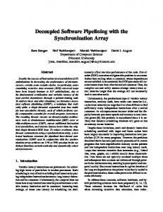
p = list; sum = 0; while (p != NULL) { id = p->id; if (!visited[id]) { visited[id] = true; q = p->inner_list; while (q != NULL && !q->flag) q = q->next; if (q != NULL) sum += p->value; } p = p->next; }
CD
C
E
D
E
FG F
H G
I H I
register dependence control dependence doall
register dependence control dependence
(b) PDG
(a) C code
sequential
(c) DAGSCC
Figure 1: (a) Example in C code, (b) PDG, (c) DAGSCC for PDG. dependences are common in most application codes outside the scientific and data-parallel arenas. Even in the domain of scientific applications, it is common for DOALL parallelism not to be directly available without employing other transformations such as loop distribution and loop skewing [1]. In many cases, DOALL parallelism is not possible even after these transformations. In such cases, other parallelization techniques that allow loop-carried dependences might be applicable, including DOACROSS [5] and DOPIPE [7]. However, these techniques are generally restricted to codes with very analyzable, array-based memory accesses, and they do not handle arbitrary control flow. Recently, a new multi-threading technique called Decoupled Software Pipelining (DSWP) was proposed [13]. DSWP extracts pipelined parallelism even from codes with irregular, pointer-based memory accesses and arbitrary control flow. These abilities enable DSWP to extract threads from general-purpose applications [13]. In essence, DSWP operates by partitioning the instructions of a loop among a sequence of loops. The new loops are concurrently executed on different threads, with dependences among them flowing in a single direction, thus forming a pipeline of threads. Since the threads form a pipeline, DSWP is not affected by increases in the inter-processor communication latency. Although applicable to a larger body of codes, DSWP misses some parallelization opportunities because each stage of the pipeline is sequentially executed in a single thread. In other words, after each recurrence in the loop is isolated in an individual pipeline stage, some stages may be free of loop-carried dependences, and thus can be parallelized in a DOALL fashion to exploit iterationlevel parallelism. In this paper, we propose Parallel-Stage DSWP (PS-DSWP), a technique to obtain pipeline parallelism with some stages executed in a DOALL fashion, and present the algorithms for applying the PS-DSWP transformation. This technique has been fully implemented in the VELOCITY multi-threading research compiler [22], and it has been used to parallelize several loops with complex memory patterns and control flow. The performance results indicate the potential of this technique to exploit iteration-level parallelism
in loops that cannot be parallelized as DOALL. Finally, our experiments present a thorough comparison between PS-DSWP and DSWP, thus quantifying the benefits of exploiting iteration-level parallelism in combination with pipelined parallelism.
2.
BACKGROUND AND MOTIVATION
This section first gives a more detailed background on the DSWP transformation [13], and then presents an example illustrating the benefits of exploiting parallel stages. We use the C code example in Figure 1(a) to illustrate how DSWP operates. This example contains a doubly nested loop that performs some computation on a list of lists, using linked data structures. The use of such pointer-based data structures, while common in general-purpose codes, usually renders other non-speculative parallelization techniques inapplicable. DSWP uses a Program Dependence Graph (PDG) [9] representation of the loop, containing both data and control dependences. Figure 1(b) illustrates the PDG for Figure 1(a). In order to partition the instructions of the loop, DSWP first groups the instructions into strongly connected components (SCCs), which precisely identify the loop’s dependence recurrences. The reason for this is that, in order to form a pipeline, the instructions in the same SCC must be assigned to the same thread. The PDG with each of its SCCs coalesced into a single node is called DAGSCC , and Figure 1(c) illustrates the DAGSCC for Figure 1(b). Theoretically, DSWP can assign each SCC in the DAGSCC to a different thread. In practice, however, the efficiency of the pipeline will be bounded by the slowest stage. In other words, the time it takes to execute the slowest SCC limits the speedup achievable by DSWP. For this reason, given a limited number of threads that can simultaneously execute in the target processor, the DSWP transformation clusters the nodes in the DAGSCC , so that all instructions in the same cluster are assigned to the same thread. DSWP employs a load-balancing heuristic to perform this clustering, also making sure that the dependences among the clusters form no cycle. As noted above, the SCCs in the PDG play an important role for DSWP since, in order to form a pipeline, they must not be parti-
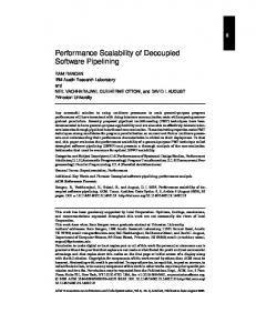
tioned. As a consequence, the maximum number of threads that DSWP can extract is limited by the number of SCCs. For example, for the loop in Figure 1, DSWP can extract a maximum of 7 threads. In practice, however, the performance of this loop is limited by the execution time of the SCC containing the inner loop formed by statements F and G (assuming the inner loop iterates many times). Therefore, DSWP clusters this DAGSCC into 3 threads, corresponding to these sets of statements: {A, B, C, D, E, J}, {F, G}, and {H, I}. Even with this clustering, the performance of this loop will be limited by the thread containing F and G (the SCC FG). A key observation is that, in Figure 1, even though FG cannot be partitioned by DSWP, it can be replicated, so that multiple threads concurrently execute this SCC for different iterations of the outer loop. This is possible because this SCC is created by dependences carried by the inner loop only, and not by the outer loop to which DSWP is applied. In other words, only dependences carried by the loop being DSWPed prevent the creation of parallel stages. In the example in Figure 1, there are dependences carried by the outer loop in the SCCs AJ, CD, and I. Although the first two of these cannot be easily eliminated, the third SCC (I) can be subjected to sum reduction [1], allowing it to be replicated. With that, PSDSWP can partition the DAGSCC in Figure 1(c) into two stages: a first, sequential stage containing SCCs AJ, B, and CD, and a second, parallel stage containing the remaining SCCs. This parallel stage can be replicated to concurrently execute in as many threads as desired, with the performance limited only by the number of iterations of the outer loop and the slowest stage in the pipeline. Figure 2 sketches the code that PS-DSWP generates for the loop in Figure 1(a), with two threads executing the parallel stage. While not shown in this figure, the actual transformation generates code to communicate the control and data dependences appropriately, and to add up the sum reduction after the loop exit. The next section describes the algorithms and techniques to enable PS-DSWP.
STAGE 2
STAGE 1
t1 id = p−>id; if (!visited[id]) visited[id] = true; p = p−>next;
t2 q = p−>inner_list; while (q!=NULL && !q−>flag) q = q−>next; if (q != NULL) sum += p−>value;
t3 q = p−>inner_list; while (q!=NULL && !q−>flag) q = q−>next; if (q != NULL) sum += p−>value;
Even iterations
Odd iterations
Figure 2: PS-DSWP applied to the loop from Figure 1(a). We note that, although loop distribution [1] is usually used to expose iteration-level parallelism in the presence of loop-carried dependences, it cannot be directly applied to uncounted loops as the one in Figure 1. Furthermore, PS-DSWP has other advantages over loop distribution, as described later in Section 6.
3. PS-DSWP TRANSFORMATION Algorithm 1 shows the pseudo-code for the PS-DSWP technique. This is based on the algorithm for the DSWP transformation proposed by Ottoni et al. [13]. It takes as input L, the loop to be optimized, and modifies it as a side-effect. The following subsections describe each step of the algorithm in detail, focusing on the ex-
Algorithm 1 PS-DSWP algorithm PS-DSWP (loop L) (1) G ← build_dependence_graph(L) (2) SCCs ← find_strongly_connected_components(G) (3) if |SCCs| = 1 then return (4) DAGSCC ← coalesce_SCCs(G, SCCs) (5) A ← assign_threads(DAGSCC , L) (6) if |A | = 1 then return (7) generate_code(L, A )
tensions to the DSWP algorithm that enable the creation of parallel stages. The loop in Figure 1 is used as a running example to illustrate the steps of the algorithm.
3.1
Building the Program Dependence Graph
The Program Dependence Graph (PDG) [9] is used to represent the loop to be parallelized. In our compiler, the PDG is built from a low-level representation of the loop. The nodes of the graph represent operations contained in the loop. An edge u → v indicates that the operation represented by v is dependent on the operation represented by u. A dependence arc can represent either a data dependence through a register1 , a data dependence through memory, or a control dependence. For registers, only true dependences are represented in the PDG [13]. Since iteration-level parallelism can be extracted only in the absence of loop-carried dependences, the dependence arcs in the PDG are annotated with a flag indicating whether the dependence is loop-carried or not. Loop-carried dependences are identified as follows: • For data dependences through memory, if array dependence analysis [1] could be applied, it is used to determine if the dependences are loop carried. Otherwise, a dependence has to be conservatively treated as loop-carried. • For data dependences through registers, data flow analysis is used to determine if they are loop-carried. Consider the dependence arc n1 → n2 . Let r be the register written by the operation corresponding to n1 . If the definition of r by n1 reaches the loop header, and there is an upwards-exposed use of r in n2 at the loop header, then the dependence is loopcarried. • For control dependences, a simple graph reachability check is used. If n1 → n2 is a control dependence and all paths in the control-flow graph from n1 to n2 contain the loop backedge, then the control dependence is considered loopcarried. Irrespective of the above categorization, the dependences between operations that can be subjected to reduction transformations and the self-arcs involving induction variables are not considered to be loop-carried, since suitable transformations can be applied to enable these operations to be executed in a parallel stage.
3.2
Obtaining the DAGSCC Once the PDG of the loop is obtained, the strongly connected components (SCCs) in this dependence graph are then identified [21] and a directed acyclic graph of them, the DAGSCC , is formed. Each node of the DAGSCC represents a strongly connected component in the original PDG. The DAGSCC for the PDG in Figure 1(b) is shown in Figure 1(c). If there is only one node in the DAGSCC , PS-DSWP 1 We use registers to denote virtual registers, which are nothing but scalar variables whose addresses are never taken.
can not parallelize the loop. If none of the edges in a strongly connected component were labeled as loop-carried dependences, the corresponding node in the DAGSCC is labeled as doall node. All other nodes are labeled as sequential nodes. If a node is labeled as doall, the operations in the SCC corresponding to that node from two different iterations can be executed concurrently.
3.3 Thread Partitioning Let D = {d1 , d2 , . . . dk } be the set of nodes in the DAGSCC . Let the number of target threads be denoted by n, and the set of threads be T = {t1 ,t2 , . . .tn }. The thread partitioning algorithm takes D and T as input and produces the following as output: • A partition P = {B1 , B2 . . . Bl } of the nodes in the DAGSCC . Each element of P corresponds to one of the l stages of the pipeline. • An assignment A = {(B1 , T1 ), (B2 , T2 ) . . . (Bl , Tl )}, which maps the blocks2 in the partition P to subsets Ti of T . The Ti s in fact partition the thread set T .
Algorithm 2 Thread Partitioning Input: DAGSCC , T Assign each node i to its own block Bi Initial partition P = {Bi |i ∈ DAGSCC } Classify each Bi as either doall or sequential D = merge_doall_blocks(P) MAXD = max_profile_weight_block(D) Reassign members of the set D − MAXD as sequential SEQ = merge_sequential_blocks(P) d = |T | − |SEQ| i=1 A = {} for n ∈ DAGSCC in topological order do if block B containing n is sequential then Add (B, {ti }) to A i = i+1 else Add (B, {ti ,ti+1 , . . .ti+d−1 }) to A i = i+d end if end for
To be valid, an assignment A obtained as above must respect the following property: P ROPERTY 1 (VALID A SSIGNMENT ). The assignment A is valid if it satisfies the following conditions: 1. For i 6= j, if there is some dependence from Bi to B j , then there are no Bk1 , Bk2 . . . Bkn , where k1 = j and kn = i, such that there is some dependence arc from every Bkl to Bkl+1 . In other words, the dependence arcs between the blocks in the partition do not form a cycle. 2. For every (Bi , Ti ), with |Ti | > 1, the DAGSCC nodes in Bi must be doall nodes, and none of the dependence arcs among the nodes in Bi is loop-carried. The first condition ensures that the blocks Bi can be mapped to threads that form a pipeline. The second condition ensures that only doall nodes are present in a parallel stage and that there are no loop-carried dependences within a parallel stage. The goal of thread partitioning is to find an assignment that minimizes the execution time. Finding the optimal solution to this problem is NP-hard, even assuming that the execution times of operations are known a priori. For this reason, a heuristic solution is used to solve the partitioning problem in this work. In our current implementation, we focus our attention only on loops that have a good amount of iteration-level parallelism. Hence, we simplify the partitioning problem by allowing only one of the pipeline stages to be assigned to more than one thread. In other words, the partitioning algorithm allows only one (Bi , Ti ) with |Ti | > 1 and, for all other (B j , T j ) pairs, |T j | = 1. Algorithm 2 shows the thread partitioning algorithm used in this work. The algorithm starts by assigning each node in the DAGSCC to its own partition block. If a node is labeled doall, the corresponding block is also labeled as doall. The partitioning algorithm then greedily merges doall blocks. Two doall blocks B1 and B2 can be merged if the following conditions are satisfied: 1. There is no block B3 such that a node in B3 is reachable from a node in B1 and a node in B2 is reachable from a node in B3 in the DAGSCC . If such a block B3 exists, then the dependences between the blocks will form a cycle among the blocks after merging, resulting in a dependence cycle among the threads. 2 An element of a partition is called block. Thus, in this paper, a block refers to a set of PDG nodes. Block does not refer to a basic block unless explicitly mentioned as such.
(a) Before
(b) After
Figure 3: Partitioning before and after merging doall nodes.
2. None of the dependence arcs connecting the PDG nodes in B1 and B2 is a loop-carried dependence arc. This is necessary to satisfy condition 2 of Property 1. This process is continued till no more merging is possible. Figure 3(a) shows the two doall blocks formed after applying the greedy algorithm. After merging, only the doall block with the maximum profile weight is retained as a doall block, while all remaining blocks are re-labeled as sequential. The sequential blocks are then merged greedily till no more merging is possible without violating the conditions for obtaining a valid assignment. Each of the sequential blocks is assigned a single thread. All the remaining threads are assigned to the sole doall block. Figure 3(b) shows the final partition for our example loop. PDG nodes E, F, G, H and I form the doall block with the largest weight. The other doall block, containing only PDG node B, is reassigned as a sequential node, and then merged with the other two sequential blocks to form a single sequential block that contains the PDG nodes A, B, C, D and J. Thus, for this loop, the PS-DSWP algorithm produces two stages, where stage 1 is a sequential stage and stage 2 is a parallel stage. After partitioning the nodes, the compiler estimates the speedup for the given partition based on the profile weight of operations in each block of the partition. The compiler applies the transformation only if the estimated speedup is above a threshold.
3.4 Code Generation
t1
t2
t3
After the partition and assignment are chosen, multi-threaded code is generated according to the following steps.
3.4.1
Distributing original loop operations
Let P = {B1 , B2 . . . Bl } be the partition obtained by thread partitioning. The instructions in B1 are left in the original loop, while the instructions in each of the other Bi s are moved and encapsulated into their own procedures F2 to Fl . These procedures are called worker-thread procedures. The creation of these procedures is described by Ottoni et al. [13]. For parallel stages, we want all the threads for a stage to execute the same thread procedure to reduce code bloat, and yet want to perform some thread specific actions. Hence, the compiler creates another procedure called Master_T hread per each thread. These Master_T hread procedures are spawned as separate threads at program initialization and each of them calls a thread procedure Fi at the beginning of each loop invocation. Fi is passed a parameter that is used to distinguish among the multiple threads that execute that Fi .
3.4.2
R1 br exit S1 S2 A1 S3 A2
B C1 S4 C2
2
D
3
J S2
Inserting inter-thread communication
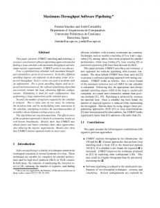
Once the operations are distributed to their respective procedures, dependences are communicated between the procedures. In the discussion that follows, we assume the use of some kind of send/receive primitives. Based on the position in the CFG where the communication operations are inserted, inter-thread communication can be classified as follows: Communication inside the loop: Consider two blocks Bi and Bi+1 produced by the thread partitioning algorithm. Let PBi and PBi+1 be the PDG nodes contained in the two blocks. Consider the set of PDG edges E = {(u, v) | u ∈ PBi , v ∈ PBi+1 }. E is the set of edges whose source node belongs to PBi and the destination node belongs to PBi+1 . The dependences represented by E need to be communicated from the thread executing the operations in Bi to the thread executing the operations in Bi+1 . The dependences communicated include both data and control dependences. To communicate a data dependence that occurs through a register, an explicit send instruction sends the value of the register immediately after the operation corresponding to the source of the dependence. On the receiving side, this value is received at the corresponding program point. If the data dependence occurs via memory, the send and receive instructions are used only for synchronization. The send/receive instructions used for memory synchronization also implement release/acquire semantics to ensure sequential memory consistency. Control dependences are communicated using a different mechanism. Consider the control dependence n1 → n2 . The node n1 must correspond to a conditional branch instruction. This dependence is communicated by replicating that branch instruction in the thread containing n2 . The direction of execution of the replicated branch mirrors that of the original branch. This requires communicating the branch direction to the other thread, which can be viewed as a data dependence communication. Since all the operations inside the loop are transitively control dependent on the loop exit branch, the loop branch is replicated in all the threads. This recreates the loop structure in all the threads. Communication between a parallel stage and a sequential stage is treated in a slightly different way. Consider a dependence n1 → n2 from a sequential stage S to a parallel stage P. Let p be the number of threads that execute the parallel stage. The sequential thread has to communicate the dependence to each of the threads in a round-robin fashion. In other words, during the ith iteration of the loop, the dependence is communicated to the (i mod p)th
1
S1 R5
8
R1 br exit
10
R2 R3 A2’
1
R4 C2’
2
E
10
R2 R3 A2’
1
R4 C2’
2
3
E
3
F
4
F
4
G
5
G
5
H
6
H
6
I
7
I
7
R2
8
R2
8
S5
9
S5
9
R1
11
R1
t1 −− t2 communication t1 −− t3 communication
Figure 4: Inter-thread communication
thread executing the parallel stage P. Section 4 discusses how our implementation of send and receive primitives permits this without requiring the thread procedure that executes P to be replicated. Figure 4 shows the communication of dependences for the loop in Figure 1. Thread t1 executes the sequential stage and threads t2 and t3 execute the parallel stage. Both t2 and t3 execute the same copy of the loop. The communications within the loop occur from t1 to t2 and t3, alternately. The communications with t2 are shown in dashed lines, and the communications with t3 are shown in dotted lines. The loop exit branch A is split into two statements A1 and A2, where A1 computes the branch condition and A2 is the actual branch. Thread t1 executes A1 and communicates the value to t2 and t3 by means of the send/receive pair (S3, R3). The branch A2 is replicated in the parallel stage as A2’, thereby completing the communication of the control dependence. This creates the loop structure in the parallel stage. The branch C is similarly communicated to t2 and t3. The data dependence from J that defines the variable p is communicated using the send/receive pair (S2, R2). Communication of live-ins: If a register defined outside the loop is used within the loop in the newly created threads, then the value of this register at loop entry needs to be communicated. Consider a procedure Fi , where i > 1, that uses a value v defined outside the loop. If Fi executes a sequential stage, then the value v is communicated to Fi at the pre-header of the loop. If Fi executes a parallel stage, then the location of communication depends on whether the value is loop-invariant or not. If the variable containing v is loop-invariant, then the value is communicated in the preheader. If the variable is redefined inside the loop, communicating the value in the pre-header will result in incorrect execution. To see this, consider the variable p in Figure 1, which is defined both outside and inside the loop. Consider that p is communicated to the
11
parallel stage outside the loop at the pre-header. Since all threads executing the parallel stage execute the same thread procedure, all of them would be initialized with the value of p outside the loop. But only the first thread executing the parallel stage has to be initialized with this value, since only that thread will execute the first iteration of the loop. In the second parallel thread, for instance, the variable p needs to be initialized with the value of p produced by the statement J in the first iteration of the loop, and not the value from outside the loop. Hence, if a variable is defined both inside and outside the loop, its value must be communicated at the loop header, instead of the pre-header. In Figure 4, the communication of the live-in variable p is shown by the send/receive pair (S2, R2) in basic block 1. Note that p is also communicated within the loop in basic block 8. In this example, the (S2, R2) pair in basic block 8 can be removed since the R3 in block 1 redefines p. However, since our optimization framework does not yet support multi-threaded redundancy elimination optimization, this communication is not removed. Communication of live-outs: All the variables that are defined inside the sequential stages and live out of the loop are communicated back to the main thread. In the parallel stages, for each register that is not control dependent on any branch within the loop, only the thread that executes the last iteration of the loop sends the value of the register. If the variable is an accumulator, all the threads send the value to the main thread. For conditionally defined variables and min/max reduction variables, all threads executing the parallel stage send both the variable and also the iteration in which the variable was last written. The use of this iteration information is described in Section 3.4.5. The only live-out variable in the example loop is the accumulator sum, whose communication is shown by the two (S5, R5) pairs.
if(cost < mincost){ mincost = cost; minnode = node; } (a) Original code if(cost < mincost){ ic = curr_iteration; mincost = cost; minnode = node; } (b) Code in parallel stages receive(mincost1) receive(minnode1) receive(ic1); receive(mincost2) receive(minnode2) receive(ic2); mincost = mincost1; minnode = minnode1; if(mincost2 < mincost){ mincost = mincost2; minnode = minnode2 } else if(mincost2 == mincost){ if(ic2 < ic1) minnode = minnode2; } (c) Merging of the results
3.4.3
Loop termination
As described above, the loop exit branches are replicated in all thread procedures to satisfy control dependences. Exit branch replication enables the threads executing sequential stages to properly terminate the loop. However, this is not sufficient for parallel stages, since only one of the threads assigned to a parallel stage executes the loop each iteration, and thus only that thread will exit the loop by taking the original loop exit. Two different approaches are used to terminate the rest of the threads executing the parallel stages, depending on where a parallel stage is located in the pipeline. If a parallel stage is the first stage of the pipeline, it implies that the loop is counted. This follows from the fact that all operations are control dependent on all loop exit branches, and an exit branch can be labeled doall only if the loop is counted. In that case, each thread executing the parallel stage counts the number of iterations they need to run and exit appropriately. If a parallel stage is not the first stage, the first (sequential) thread, which is guaranteed to execute the loop exit branch, explicitly communicates loop termination information to the threads executing the parallel stage. The first thread sends a true token at the loop header to the thread that is going to execute the current iteration. On loop termination, it sends a false token to all the threads. Since the parallel-stage thread that has exited the loop by taking the loop exit branch also receives a false token, it has to consume that token after exiting the loop. The communication of this exit token is shown by the (S1, R1) pair in Figure 4. Basic block 10 in t2 and t3 has a branch that exits based on the value received by R1. This token is sent by t1 in basic block 1 within the loop, and basic block 9 outside the loop. Either t2 or t3 exits the loop by executing the original loop exit branch and consumes this token in basic block 11.
Figure 5: Example of conditionally defined live-outs
3.4.4
Handling induction variables
Our thread partitioning algorithm could assign a loop induction variable to a parallel stage. In that case, the compiler needs to suitably initialize the induction variables at the beginning of each thread. Consider a basic induction variable of the form i = i+k. Let i0 be the initial value of i before entering the loop. Let 0, 1, . . . , p−1 be the thread identifiers of the threads executing the parallel stage that increments the induction variable. As described above, this thread identifier is passed as a parameter (id) to the thread procedure. In the parallel stage, the variable i is initialized to i0 + id × k at the loop’s pre-header. Thus each thread executing the parallel stage initializes the variable with a different value. Inside the loop, instead of incrementing the variable by k, it is incremented by p×k.
3.4.5
Handling loop live-outs
Different types of loop live-outs defined in parallel stages need to be handled differently. If a live-out is an accumulator, all threads executing the parallel stage send the values to the main thread at loop termination, and the main thread sums them up. For other live-outs that are not conditionally defined, only the thread that executes the last iteration of the loop sends the value to the main thread. Conditionally defined live-outs pose an additional problem. To see this, consider the code fragment in Figure 5(a). Assuming that the computation of mincost and minnode is reducible, this code fragment can be part of a parallel stage. If that parallel stage is executed by two threads, one of them computes the minimum of the
A: B: C:
int a[N], b[N], c[N]; for(i = 1; i < N; i++){ a[i] = a[i]*b[i]; c[i] = c[i-1]+a[i]; } (a) Loop affected by false sharing
cache lines array elements
(b) Without chunking
(c) With chunking
Figure 6: False sharing cost variable and the associated node in all even iterations, and the other thread computes them in all odd iterations. To correctly obtain the value of minnode, we need to keep track of which iteration in each of the two threads finally wrote the mincost values. Figure 5(b) shows that a variable ic is assigned the current iteration count whenever mincost is assigned. Figure 5(c) shows how the main thread merges the two values. If mincost produced by one thread is less than the mincost produced by the other thread, the lesser value and the associated minnode is chosen. If the values are equal, then the iteration count is used to determine the correct value of minnode.
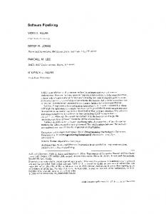
3.5 Parallelism versus False Sharing The transformation described above causes the iterations of the parallel stage to be executed in a round-robin fashion among all the threads assigned to that stage. This could result in the problem of false sharing, which could negate the benefits of parallelism obtained by the PS-DSWP transformation. False sharing can occur on multi-processors that implement an invalidation-based cachecoherence protocol when two or more different processors alternately write to different locations in the same cache line. Consider the loop in Figure 6(a). PS-DSWP can parallelize this loop into a first parallel stage containing statements A and B executed by two threads followed by the sequential stage executing C. The first thread executing the parallel stage writes to array elements a[1], a[3], a[5] and so on, and the second thread writes to even elements of the array a. This is depicted in Figure 6(b). Each row in the figure represents a cache line, and each cell represents an array element. For the sake of this discussion, we assume that the cache-line size is 4 times the size of an element, and that the array is aligned to the cache-line boundary. The two different
shades in the cells represent the two different processors that execute the parallel stage, and hence write to the cache line. Since both threads write to the same cache line most of the time, the exclusive ownership of the cache lines ping-pong between the two processors. This increases the latency of every access to a. If this increase in latency is huge, it could negate the benefits of executing the pipeline stage in parallel. False sharing can be eliminated in certain cases by applying iteration chunking. Each of the threads executing the parallel stage would execute chunks of contiguous iterations, instead of just one iteration, in a round-robin fashion. For the example in Figure 6(a), let us assume that the two parallel threads execute chunks of 4 iterations each. The writes to array a now exhibit a pattern shown in Figure 6(c). Each cache line is now written to by only one processor, and the two processors write to alternate cache lines. This eliminates false sharing. However, chunking could reduce the amount of parallelism. In the extreme case, the chunk size can equal the total number of iterations of the loop in a given invocation, which is equivalent to treating that stage as a sequential stage. In our current implementation, some simple heuristics are employed to determine a chunk size that would not significantly reduce the parallelism. The compiler first checks if the parallel stage contains writes to array elements. If none of these writes are indexed by a basic induction variable, the compiler does not chunk the iterations since it can not analyze the resulting access pattern. For each access indexed by a basic induction variable, the stride of the induction variable (stride) and the size of each element of the array (size) are computed. Let cls be cls the size of the cache line. A chunk size of stride×size would eliminate false sharing for this array access. This is computed for all accesses, and let cs be the largest of the chunk sizes among those accesses. If cs is chosen as the chunk size, it would eliminate false sharing. This chunk size is chosen by the compiler only if the average trip count of the loop per thread executing the parallel stage is much higher than the chunk size cs. Chunking requires some additional changes in the transformation described earlier. In particular, the increment of induction variable by a parallel thread has to be modified. Consider an induction variable defined by the operation i = i + 1. In the original sequential loop, i takes the values i0 , i0 + 1, i0 + 2 . . . i0 + k. If that operation is part of a parallel stage executed by two threads without chunking, the variable takes the values i0 , i0 + 2, i0 + 4 . . . in the first thread. If chunking with chunk size of 2 is used, i now takes the values i0 , i0 + 1, i0 + 4, i0 + 5, . . . in the first thread. The other change is in the sequential stages that interact with the chunked parallel stage. These stages now communicate with each thread for every contiguous cs iterations before moving to the next thread in a round-robin fashion. To implement this, a new counter, that increments from 0 to cs − 1 and wraps back to 0, is added to each stage.
4.
ARCHITECTURAL SUPPORT
PS-DSWP does not rely on any hardware support to ensure correctness of the generated code, which can execute on any commodity multiprocessor system. While the abstract send/receive primitives used in the description of the PS-DSWP transformation can be implemented in a commodity multiprocessor using the memory subsystem and mutex primitives, we use a dedicated inter-core communication hardware for performance reasons. Since the communication between the threads in PS-DSWP is unidirectional inside the loop, communication latency does not have a significant impact on the performance of PS-DSWP. However, the overhead of executing the communication and synchronization operations
Core
Shared L3 Cache Main Memory Coherence L3 Bus
Functional Units: 6 issue, 6 ALU, 4 memory, 2 FP, 3 branch L1I Cache: 1 cycle, 16 KB, 4-way, 64B lines L1D Cache: 1 cycle, 16 KB, 4-way, 64B lines, write-through L2 Cache: 5,7,9 cycles, 256KB, 8-way, 128B lines, write-back Maximum Outstanding Loads: 16 > 12 cycles, 1.5 MB, 12-way, 128B lines, write-back Latency: 141 cycles Snoop-based, write-invalidate protocol 16-byte, 1-cycle, 3-stage pipelined, split-transaction bus with round robin arbitration
Table 1: Machine details. can have an adverse effect on performance. This is especially true in loops with a short body, where the overhead of executing a sequence of instructions per iteration to lock a shared data structure, communicate the values, and unlock the data structure may be significant. In this work, we use the synchronization array [16] to reduce the queue communication and synchronization overheads. The synchronization array provides a low-overhead inter-core communication and synchronization mechanism, and essentially consists of a set of hardware-implemented queues between the cores. The interface to the synchronization array proposed by Rangan et al. [16] is in the form of produce and consume instructions. The produce instruction takes a register and a queue number as its operands, and sends the register to the queue specified by the queue number. Similarly, the consume instruction takes a register and a queue number as its operands, and consumes the value from the head of the queue into the specified register. In PS-DSWP, multiple threads executing a parallel stage all share the same code. But each of them has to use a different queue to communicate with other stages, since a queue is only a point-topoint communication channel. This requires a mechanism whereby the queue numbers used in produce and consume instructions are transparently renamed to different physical queues. To support this, we add a special queue-base register to each processor core. The physical queue numbers are obtained by adding the virtual queue numbers in the produce/consume instructions to the value in the queue-base register. A new instruction, called queue.set, is added to set the value of the queue-base register. The round-robin communication between the sequential and the parallel threads is achieved by suitably changing the queue-base register in each of the cores.
5. EXPERIMENTAL EVALUATION This section describes our experimental evaluation of PS-DSWP. The base model used is a 6-core Itanium 2 CMP developed using the Liberty Simulation Environment (LSE). The cores are validated (IPC and constituent error components accurate to within 6% of real hardware for benchmarks measured [15]), and the details of each core in the model are given in Table 1. To this base model, a synchronization array with 512 queues, each with 32 entries, was added. The produce, consume and queue.set instructions are also modeled in the pipeline of the Itanium 2 cores. We have implemented PS-DSWP in the VELOCITY research compiler [22]. The applications are first compiled into a low-level intermediate representation, and then transformed by a round of classical optimizations. PS-DSWP was then automatically applied to the selected loops. Translation to Itanium 2 instructions is followed by another round of classical optimizations, scheduling, register allocation, and a final scheduling phase. The results reported are in terms of loop speedup over single-threaded binary, which is obtained by the same sequence of optimizations except PS-DSWP.
Except for the loop being optimized, the rest of the application remains unchanged. Consequently, detailed performance simulation is done only for the loops being optimized. The caches and branch predictors are kept warm while the rest of the application is executed on a fast-forward mode. To evaluate PS-DSWP, the compiler identified a set of loops that can not be parallelized by DOALL and contributes to at least 15% of the application’s execution time. The compiler first estimated the potential speedup based on the profile weights of the operations in the partition and the communication operations. If the estimated speedup is less than 50% with 6 threads, the compiler does not transform the loop. This is used as a heuristic to avoid slowdown of the parallel code compared to the single threaded code. The details of the selected loops are presented in Table 2. The loop in 300.twolf had to be manually annotated to indicate the absence of a memory dependence, since the pointer analysis used in our compiler is not powerful enough to conclude that. The nature of the pipeline stages obtained as a result of applying the PS-DSWP transformation is also given in the final column of Table 2. In this column, an s indicates a sequential stage and a p indicates a parallel stage. Thus, for instance, otter is parallelized into three pipeline stages, with a parallel stage sandwiched between two sequential stages. Figures 7(a)-(e) show the performance of the five selected loops after applying PS-DSWP. For each loop, the graphs compare the speedups obtained by DSWP and PS-DSWP for the same number of threads. PS-DSWP shows a speedup of up to 155% in 458.sjeng, and a geometric-mean speedup of 114% among these 5 loops, using up to 6 threads. In comparison, the geometricmean speedup of DSWP in these loops is 36%, also using up to 6 threads. In all the benchmarks except 300.twolf, PS-DSWP outperforms DSWP for any given number of threads. The body of the loop in 300.twolf is large with many SCCs allowing DSWP to obtain a good balanced partition. However, the loop in 300.twolf executes for only between 3 to 4 iterations on average. Hence executing the parallel stage in more than 3 threads results in diminishing returns. The loop in 456.hmmer also shows poor scalability, even though the loop iterates for 300 times per invocation. In 456.hmmer, the sequential stage takes a significant amount of time to execute and starts to become the bottleneck after a replication factor of 3 for the parallel stage. In the other three loops, PS-DSWP shows scalability up to 6 threads, while DSWP plateaus immediately. The poor scalability in these benchmarks can be overcome by a better thread partitioning algorithm that tries to do load balancing between the stages. Figure 7(f) shows the importance of applying iteration chunking to the loop in 456.hmmer with 4 threads. The bar on the left shows the speedup obtained when iteration chunking was not applied. The second bar shows the speedup for the same code when all data accesses were assumed to always hit in the L1 cache. This speedup number is relative to a single-threaded baseline which was also simulated with a perfect cache. The difference in these speedups indicates that cache effects significantly influence the speedup of the multi-threaded code in this loop. The third bar shows that most of this difference goes away on our original cache model shown in Table 1 when the compiler uses a chunk size of 32. This suggests that chunking can be effective in mitigating the effects of false sharing. The final bar shows the speedup of the chunked code with a perfect data cache. This speedup is less than what can be obtained by using a perfect cache when chunking is not applied, indicating that iteration chunking results in a loss of parallelism.
Benchmark ks otter 300.twolf 456.hmmer 458.sjeng
Description Kernighan-Lin graph partitioning theorem prover for first-order logic placement and routing hidden markov model chess program
Loop FindMaxGpAndSwap (outer) find_lightest_geo_child new_dbox_a (outer) P7_Viterbi (inner) std_eval
Hotness 98% 15% 30% 85% 26%
Pipeline stages s→ p s→ p→s s→ p p→s s→ p
Table 2: Benchmark Details DSWP PS-DSWP
DSWP PS-DSWP
3.0
2.0 1.5 1.0
2.5 2.0 1.5 1.0
3
4
5
4
5
6
3
2.0 1.5 1.0 6
2.5 2.0 1.5
3
4
Number of Threads
(d) 458.sjeng
6
3.0
1.0 5
5
(c) 300.twolf
Loop Speedup
2.5
4
Number of Threads
DSWP PS-DSWP
3.0 Loop Speedup
Loop Speedup
1.5
(b) otter
DSWP PS-DSWP
4
2.0
Number of Threads
(a) ks
3
2.5
1.0
6
Number of Threads
3.0
DSWP PS-DSWP
3.0 Loop Speedup
2.5
Loop Speedup
Loop Speedup
3.0
5
6
2.5 2.0 1.5 1.0 CS1
CS1-Perf
CS32
CS32-Perf
Number of Threads
(e) 456.hmmer
(f) Effects of chunking on 456.hmmer with 4 threads
Figure 7: Speedups Over Single-threaded Execution
6. RELATED WORK Several automatic techniques have been proposed to extract thread-level parallelism. The techniques closest to PS-DSWP are DSWP [13, 16] and loop distribution [11]. As discussed earlier, PS-DSWP is an extension of DSWP to also exploit iteration-level parallelism. PS-DSWP is similar to loop distribution in the sense that both techniques isolate the parts of loop with loop-carried dependences from the parts without these dependences. The main difference between PS-DSWP and loop distribution combined with DOALL is that PS-DSWP allows the execution of the sequential part of the loop to overlap with the DOALL part, using pipeline parallelism. Moreover, loop distribution, as proposed in literature, does not permit arbitrary control flow within the region. Finally, the use of synchronization array in PS-DSWP allows it to operate on uncounted loops. DOPIPE [7, 14] is another technique that exploits pipeline parallelism. Unlike DSWP, DOPIPE does not handle loops with control flow inside. Davies [7] also proposes executing multiple copies of a DOPIPE stage if that stage contains an inner DOALL loop. The PS-DSWP technique is more general because it can create parallel stages without requiring the operations to be inside an inner
DOALL loop. DOACROSS [5] is another non-speculative technique that can be used to extract iteration-level parallelism on loops with loopcarried dependences. DOACROSS does not permit control flow within the loop. Moreover, DOACROSS does not result in a pipeline of stages. The inter-thread dependences in DOACROSS form a cycle and would be the bottleneck as the latency of inter-core communication increases. Similar to DSWP, inter-core communication latency has negligible impact on the performance of PS-DSWP. While PS-DSWP is a non-speculative technique, several speculative techniques have been proposed to extract iteration-level parallelism. Thread-level speculation (TLS) [10, 12, 19, 20] techniques speculatively execute consecutive iterations of a loop concurrently, assuming that the dependences between those iterations are infrequent. Inter-iteration dependences that manifest frequently are synchronized. Other speculative parallelization techniques such as LRPD test [17], R-LRPD test [6] and master/slave speculative parallelization [24] have also been proposed to speculatively extract iteration-level parallelism. Speculative DSWP [23] adds speculation support to DSWP. The addition of speculation can increase the number of pipeline stages
in a loop since speculating dependences might breakup some of the SCCs. Bridges et al. [2, 3] have shown that DSWP in combination with speculation and parallel stages has the potential to unlock parallelism among all the programs in the SPEC2000 integer benchmark suite.
[10]
[11]
7. CONCLUSION This paper presented a new non-speculative compiler transformation called Parallel-Stage Decoupled Software Pipelining (PSDSWP). PS-DSWP combines the pipeline parallelism of DSWP [13, 16] with iteration-level parallelism of DOALL [1] in a single transformation. This paper described in detail the algorithms and the compiler implementation required to automatically apply the PSDSWP transformation. We evaluated PS-DSWP on a set of complex loops from general-purpose applications. PS-DSWP showed up to 155% (114% on average) speedup with up to 6 threads on this set of loops, and showed better scalability than DSWP.
Acknowledgments We thank the entire Liberty Research Group for their support and feedback during this work. Additionally, we thank the anonymous reviewers for their insightful comments. The authors acknowledge the support of the GSRC Focus Center, one of five research centers funded under the Focus Center Research Program, a Semiconductor Research Corporation program. This work has been supported by Intel Corporation. Opinions, findings, conclusions, and recommendations expressed throughout this work are not necessarily the views of our sponsors.
[12]
[13]
[14]
[15]
[16]
[17]
8. REFERENCES [1] R. Allen and K. Kennedy. Optimizing compilers for modern architectures: A dependence-based approach. Morgan Kaufmann Publishers Inc., 2002. [2] M. J. Bridges, N. Vachharajani, Y. Zhang, T. Jablin, and D. I. August. Revisiting the sequential programming model for multi-core. In Proceedings of the 40th Annual ACM/IEEE International Symposium on Microarchitecture, pages 69–81, 2007. [3] M. J. Bridges, N. Vachharajani, Y. Zhang, T. Jablin, and D. I. August. Revisiting the sequential programming model for the multicore era. IEEE Micro, January 2008. [4] J. C. Corbett. Evaluating deadlock detection methods for concurrent software. IEEE Transactions on Software Engineering, 22(3):161–180, 1996. [5] R. Cytron. DOACROSS: Beyond vectorization for multiprocessors. In Proceedings of the International Conference on Parallel Processing, pages 836–884, 1986. [6] F. H. Dang, H. Yu, and L. Rauchwerger. The R-LRPD test: Speculative parallelization of partially parallel loops. In IPDPS ’02: Proceedings of the 16th International Parallel and Distributed Processing Symposium, page 318, 2002. [7] J. R. B. Davies. Parallel loop constructs for multiprocessors. Master’s thesis, University of Illinois, Urbana, IL, May 1981. [8] P. A. Emrath and D. A. Padua. Automatic detection of nondeterminacy in parallel programs. In Proceedings of the 1988 ACM SIGPLAN and SIGOPS Workshop on Parallel and Distributed Debugging, pages 89–99, New York, NY, USA, 1988. ACM Press. [9] J. Ferrante, K. J. Ottenstein, and J. D. Warren. The program dependence graph and its use in optimization. ACM
[18]
[19]
[20]
[21] [22]
[23]
[24]
Transactions on Programming Languages and Systems, 9:319–349, July 1987. L. Hammond, B. A. Hubbert, M. Siu, M. K. Prabhu, M. Chen, and K. Olukotun. The Stanford Hydra CMP. IEEE Micro, 20(2):71–84, 2000. K. Kennedy and K. S. McKinley. Loop distribution with arbitrary control flow. In Proceedings of Supercomputing ’90, pages 407–416, November 1990. P. Marcuello and A. González. Clustered speculative multithreaded processors. In Proceedings of the 13th International Conference on Supercomputing, pages 365–372, New York, NY, USA, 1999. ACM Press. G. Ottoni, R. Rangan, A. Stoler, and D. I. August. Automatic thread extraction with decoupled software pipelining. In Proceedings of the 38th IEEE/ACM International Symposium on Microarchitecture, pages 105–116, November 2005. D. A. Padua. Multiprocessors: Discussion of Some Theoretical and Practical Problems. PhD thesis, University of Illinois, Urbana, IL, November 1979. D. A. Penry, M. Vachharajani, and D. I. August. Rapid development of a flexible validated processor model. In Proceedings of the 2005 Workshop on Modeling, Benchmarking, and Simulation, June 2005. R. Rangan, N. Vachharajani, M. Vachharajani, and D. I. August. Decoupled software pipelining with the synchronization array. In Proceedings of the 13th International Conference on Parallel Architectures and Compilation Techniques, pages 177–188, September 2004. L. Rauchwerger and D. A. Padua. The LRPD test: Speculative run-time parallelization of loops with privatization and reduction parallelization. IEEE Transactions on Parallel and Distributed Systems, 10(2):160–180, 1999. S. Savage, M. Burrows, G. Nelson, P. Sobalvarro, and T. Anderson. Eraser: A dynamic data race detector for multithreaded programs. ACM Transactions on Computer Systems, 15(4):391–411, 1997. G. S. Sohi, S. Breach, and T. N. Vijaykumar. Multiscalar processors. In Proceedings of the 22th International Symposium on Computer Architecture, June 1995. J. G. Steffan, C. Colohan, A. Zhai, and T. C. Mowry. The STAMPede approach to thread-level speculation. ACM Transactions on Computer Systems, 23(3):253–300, 2005. R. E. Tarjan. Depth-first search and linear graph algorithms. SIAM Journal on Computing, 1(2):146–160, 1972. S. Triantafyllis, M. J. Bridges, E. Raman, G. Ottoni, and D. I. August. A framework for unrestricted whole-program optimization. In Proceedings of the ACM SIGPLAN Conference on Programming Language Design and Implementation, pages 61–71, June 2006. N. Vachharajani, R. Rangan, E. Raman, M. J. Bridges, G. Ottoni, and D. I. August. Speculative decoupled software pipelining. In Proceedings of the 16th International Conference on Parallel Architectures and Compilation Techniques, September 2007. C. Zilles and G. Sohi. Master/slave speculative parallelization. In Proceedings of the 35th Annual International Symposium on Microarchitecture, pages 85–96, Los Alamitos, CA, USA, 2002. IEEE Computer Society Press.