Parallel Tools in HEVC for High-Throughput Processing Minhua Zhou1, Vivienne Sze, Madhukar Budagavi Texas Instruments Inc, 12500 TI Blvd., Dallas, TX-75243 ABSTRACT HEVC (High Efficiency Video Coding) is the next-generation video coding standard being jointly developed by the ITU-T VCEG and ISO/IEC MPEG JCT-VC team. In addition to the high coding efficiency, which is expected to provide 50% more bit-rate reduction when compared to H.264/AVC, HEVC has built-in parallel processing tools to address bitrate, pixel-rate and motion estimation (ME) throughput requirements. This paper describes how CABAC, which is also used in H.264/AVC, has been redesigned for improved throughput, and how parallel merge/skip and tiles, which are new tools introduced for HEVC, enable high-throughput processing. CABAC has data dependencies which make it difficult to parallelize and thus limit its throughput. The prediction error/residual, represented as quantized transform coefficients, accounts for the majority of the CABAC workload. Various improvements have been made to the context selection and scans in transform coefficient coding that enable CABAC in HEVC to potentially achieve higher throughput and increased coding gains relative to H.264/AVC. The merge/skip mode is a coding efficiency enhancement tool in HEVC; the parallel merge/skip breaks dependency between the regular and merge/skip ME, which provides flexibility for high throughput and high efficiency HEVC encoder designs. For ultra high definition (UHD) video, such as 4kx2k and 8kx4k resolutions, low-latency and real-time processing may be beyond the capability of a single core codec. Tiles are an effective tool which enables pixel-rate balancing among the cores to achieve parallel processing with a throughput scalable implementation of multi-core UHD video codec. With the evenly divided tiles, a multi-core video codec can be realized by simply replicating single core codec and adding a tile boundary processing core on top of that. These tools illustrate that accounting for implementation cost when designing video coding algorithms can enable higher processing speed and reduce implementation cost, while still delivering high coding efficiency in the next generation video coding standard. Keywords: video coding, HEVC, parallel processing, throughput, CABAC, parallel merge/skip, tiles
1. INTRODUCTION HEVC (High Efficiency Video Coding)[2] is the next generation video compression standard being jointly developed by the Joint Collaborative Team on Video Coding (JCT-VC) of ITU-T WP3/16 and ISO/IEC JTC 1/SC 29/WG 11. In addition to 50% more bit-rate reduction than H.264/AVC, HEVC also enables high throughput processing by utilizing a variety of coding efficiency enhancement and parallel processing tools. High throughput processing is necessary in order to meet the growing demand for the higher resolutions (e.g. ultra high definition 4kx2k and 8kx4k) and frame rates (e.g. 120 frames per second (fps)). The degree of parallelism that can be achieved with architecture optimizations is often limited by the algorithm itself; thus it is important to account for the need for parallel processing during the design of the algorithms, and accordingly the design of the HEVC standard. This paper focuses several key tools in HEVC that enable high throughput processing including high throughput CABAC, parallel merge/skip and tiles for parallel decoding.
2. HIGH THROUGHPUT CABAC Context-Adaptive Binary Arithmetic Coding (CABAC) is a form of entropy coding that was introduced in H.264/AVC [3] and also used in HEVC [2]. While CABAC provides high coding efficiency, its tight data dependencies cause it to be a throughput bottleneck for H.264/AVC video codecs. The throughput of CABAC is determined based on the binary symbols (bins) that can process per second. Syntax elements of the transform coefficient data, which represent the residual of the prediction error, account for a significant portion of the bin workload. For instance, under common conditions, transform coefficient data accounts for up to 90% of the total bins. The transform coefficients also account for a significant portion of the total bits of a compressed video, and therefore impact the overall coding efficiency of the
1
[email protected]; phone 1 214 480-3816; fax 1 972 761-6969; Applications of Digital Image Processing XXXV, edited by Andrew G. Tescher, Proc. of SPIE Vol. 8499, 849910 · © 2012 SPIE · CCC code: 0277-786/12/$18 · doi: 10.1117/12.953686
Proc. of SPIE Vol. 8499 849910-1 Downloaded From: http://proceedings.spiedigitallibrary.org/ on 10/23/2014 Terms of Use: http://spiedl.org/terms
video codec. Thus, transform coefficient coding with CABAC must be carefully designed in order to balance coding efficiency and throughput demands. Several tools were adopted into CABAC for HEVC to enable parallel processing of transform coefficients. This section will discuss how CABAC transform coefficient coding has changed from H.264/AVC to HEVC. Section 2.1 provides an overview of CABAC entropy coding to explain the cause of the throughput bottleneck. Section 2.2 describes the key steps in transform coefficient coding using CABAC. Section 2.3 and Section 2.4 describes changes to transform coefficient coding that enable increased throughput and higher coding efficiency for HEVC. 2.1 CABAC Throughput Entropy coding is a form of lossless compression used to minimize the number of bits required to represent syntax elements. Arithmetic coding is a type of entropy coding that can achieve compression close to the entropy of a sequence by effectively mapping the symbols (i.e. syntax elements) to codewords with non-integer number of bits. In H.264/AVC, CABAC provides a 9 to 14% improvement over the Huffman-based CAVLC [4]. CABAC involves three main functions as shown in Figure 1: binarization, context selection/modeling, and arithmetic coding. Binarization maps syntax element to binary symbols (bins). Context selection and modeling estimates the probability of the bins and arithmetic coding compresses the bins. CABAC is a highly serial process and a well known bottleneck in H.264/AVC video codec implementations. This makes it difficult to achieve the high throughput necessary for high resolution and frame-rate videos. Furthermore, since high throughput can be traded-off for power savings using voltage scaling, the serial nature of CABAC limits the battery life for video codecs that reside on mobile devices. Multiple feedback loops exist in the CABAC that make it highly serial as shown in Figure 1. There are feedback loops in the range update for arithmetic coding (#1) and context (probability model) update (#2); however, the loops that make it most difficult to increase the CABAC throughput are due to the data dependencies for context selection (#3 and 4 in Figure 1). The context selection for a bin can depend on the value of a previously encoded/decoded bin. This tight dependency makes parallelism difficult and costly to achieve, particularly at the decoder, if multiple bins are to be decoded at the same time. If the context of a bin depends on the value of another bin being decoded in parallel, then speculative computations are required which increases area cost and critical path delay. The amount of speculation grows exponentially with the number of parallel bins which limits the throughput that can be achieved. For HEVC, improvements have been made to the context selection and coefficient scanning in order to reduce the amount of speculation required to process multiple bins in parallel. range update
bin
syntax elements
Binarization
1
bin index probability
Context Selection
bitstream
2 context update
ENCODER
bin range update
DeBinarization bin index
1 bitstream
Arithmetic Encoder
Arithmetic Decoder
probability
4
syntax elements 3
Context Selection
2 context update DECODER
Figure 1: The CABAC is composed of three key blocks: binarization, context selection and modeling and arithmetic coding. Feedback loops are highlighted with dashed lines.
Proc. of SPIE Vol. 8499 849910-2 Downloaded From: http://proceedings.spiedigitallibrary.org/ on 10/23/2014 Terms of Use: http://spiedl.org/terms
2.2 Overview of Transform Coefficient Coding In video coding, both intra and inter prediction are used to reduce the amount of data that needs to be transmitted. Rather than sending the pixels, the prediction error is transmitted. This prediction error is transformed from spatial to frequency domain and can be represented by a few quantized transform coefficients. The method of signaling the value and the frequency position of these coefficients is referred to as transform coefficient coding. In CABAC, the positions of the coefficients are transmitted in the form of a significance map. Specifically, the significance map indicates the location of the non-zero coefficients. The coefficient level information is only transmitted for the coefficients with values greater than one, while the coefficient sign is transmitted for all non-zero coefficients. An example of transform coefficient coding in H.264/AVC is shown in Figure 2. 9 -5 3 0
0 0 1 0
0 -1 0 0 0 0 0 0
0
1
5
6
2
4
7
12
8
11 13
3 9 0
Zig-zag Scan
10 14 15
significant_coeff_flag
1
1
1
last_siginificant_coeff_flag
0
0
0
0
0
0
1
0
1 1
coeff_abs_level_minus1
8
4
2
0
0
coeff_sign_flag
0
1
0
1
0
Signaling order 1 0 0 1 0 1 0 0 0 0 1 0 0 1 1 1 8 0 4 1 2 0 0 1 0 0 Significant map
Coefficient level and sign
Figure 2: Example of transform coefficient coding used in H.264/AVC.
2.3 Significance Map In H.264/AVC, the significance map is signaled by transmitting a significant_coeff_flag (SCF) for each position to indicate whether the coefficient is non-zero. The positions are processed in an order based on a zig-zag scan. After each non-zero SCF, an additional flag called last_significant_coeff_flag (LSCF) is immediately sent to indicate whether it is the last non-zero SCF; this prevents unnecessary SCF from being signaled. Different contexts are used depending on the position within the transform unit (TU), and whether the bin represents an SCF or LSCF. Since SCF and LSCF are interleaved, the context selection of the current bin depends on the immediate preceding bin. The dependency of LSCF on SCF results in a strong bin to bin dependency for context selection for significance map in the H.264/AVC. In the first version of the HEVC test model (HM-1.0), additional dependencies were introduced between SCF to improve coding efficiency [5]. The context selection for SCF can depend on the number of non-zero neighbors to give coding gains between 1.4 to 2.8% [6]. Specifically, the context of SCF depends on up to 10 neighbors as shown in Figure 3.
Figure 3: Dependencies on neighbors in context selection of significant_coeff_flag in the first version of HEVC test model (HM-1.0).
Using the neighboring coefficient introduces additional context selection dependencies on the previously processed bins, which makes it difficult process multiple bins per cycle [7]. Methods to minimize this dependency were explored including reducing the number of neighbors from 10 to 5 [8] and modifying the scan order of the coefficients from zigzag to diagonal [9]. These techniques significantly reduced context selection dependency, with minimal impact to
Proc. of SPIE Vol. 8499 849910-3 Downloaded From: http://proceedings.spiedigitallibrary.org/ on 10/23/2014 Terms of Use: http://spiedl.org/terms
coding efficiency, and thus were adopted into various versions of HM. In [10], it was shown that context selection dependencies between SCF within a 4x4 sub-block can be removed by using neighboring sub-blocks rather than neighboring coefficient positions for context selection of SCF as shown in Figure 4. Specifically, the context selection of SCF in the current sub-block would depend on whether there were any non-zero coefficients in the bottom and right neighboring 4x4 sub-blocks. Thus the context selection for all SCF within a 4x4 sub-block can be done in parallel. This reduced dependency on the previously processed bins, since neighboring sub-blocks are typically processed several cycles before the current sub-block, making it unlikely that there would be dependency between SCF bins processed in the same cycle.
Current sub-block Check for non-zeros Figure 4: Context selection of significant_coeff_flag in current sub-block depends on whether right and bottom sub-blocks contain non-zero coefficients.
As mentioned earlier, there are strong data dependencies between SCF and LSCF. The concept of parallel context processing (PCP) is introduced in [11] to address this concern by reducing interleaving of SCF and LSCF. PCP is used in [13] to avoid interleaving of SCF and LSCF altogether. Specifically, the X, Y position of the last non-zero SCF (last_significant_coeff_x and last_significant_coeff_y) is sent rather than LSCF. For instance, in the example of shown in Figure 2, last_significant_coeff_x equal to 3 and last_significant_coeff_y equal to 0 is sent rather than last_significant_coeff_flag. 2.4 Level Coding In H.264/AVC, the coefficient level is composed of two parts. The first 14 bins, generated with truncated unary binarization, are context coded (i.e. require context selection). The remaining bins, generated by exp-golomb binarization, are bypass coded bins, which means that a fixed equal probability of 0.5 is assumed and thus do not require context selection. After each coefficient level is signaled, the sign is signaled with one bypass bin. It is important to note that bypass coded bins can be processed in parallel much easier than context coded bins. Parallel context processing (PCP) for coefficient level and sign was proposed in [12]. As with significance map, reducing the interleaving of bins coded with different contexts reduces the data dependencies for context selection. If the context switches less from bin to bin, then less speculative computations are required. Thus the first bin of coefficient levels are grouped together and the sign bins are grouped together. PCP can be further leveraged with the new binarization scheme for coefficient levels introduced in [14]. The coefficient level is composed of three parts. Only the first two bins (coeff_abs_level_greater1_flag and coeff_abs_level_greater2_flag) are context coded and the remaining bins, generated with Golomb-Rice binarization, are bypass coded (coeff_abs_level_remaining). In [15], PCP is applied to the second bin of the coefficient level. As a result, all bypass coded bins are grouped together which maximizes the throughput advantages of bypass bins. coeff_abs_level_remaining across multiple coefficients are grouped together and sign bins are grouped together as shown in Figure 5. To reduce storage cost, the sign bins are signaled before coeff_abs_level_remaining bins. This reordering of data to enable parallel context processing has no impact on coding efficiency.
Figure 5: Parallel Context Processing (PCP) in coefficient levels. All bypass bins are grouped together to increase throughput.
Proc. of SPIE Vol. 8499 849910-4 Downloaded From: http://proceedings.spiedigitallibrary.org/ on 10/23/2014 Terms of Use: http://spiedl.org/terms
Finally, in [16], the maximum number of coeff_abs_level_greater1_flag and coeff_abs_level_greater2_flag per 4x4 subblock are reduced from 16 to 8 and 1 respectively. This reduces the number of context coded bins, and replaces them with bypass bins which can be processed at a higher throughput. 2.5 Summary Methods such as parallel context processing and diagonal scans are used to reduce data dependencies in CABAC transform coefficient coding for HEVC. An example of transform coefficient coding in HEVC is shown in Figure 6.
Figure 6: Example of transform coefficient coding used in HEVC.
Transform coefficient coding for HEVC has been carefully design to deliver higher throughput and higher coding efficiency as compared with H.264/AVC. Dependencies for context selection of consecutive bins have been reduced for significance map and coefficient level in order to enable multiple bins to be processed in parallel. In addition, the number of context coded bins in coefficient level has been significantly reduced. At same time, new tools for improved coding efficiency (e.g. using neighbors for context selection of SCF) have been simplified to meet this requirement. Similar approaches of grouping bypass bins have also been applied to syntax elements beyond transform coefficients (e.g. intra prediction mode, motion vectors) to speed up CABAC and reduce hardware cost.
3. PARALLEL MERGE/SKIP HEVC uses a different coded block structure as compare with H.264/AVC. Specifically, HEVC uses larger blocks compare to H.264/AVC. The largest coding unit (LCU) is 64x64 pixels which is 16 times larger than the 16x16 pixel macroblock in H.264/AVC. Using a large coding unit helps to improve coding efficiency, particularly for high resolutions where many pixels may share the same characteristic. Furthermore, the largest coding unit can be divided into smaller coding units using a quad tree structure as shown in Figure 7. A split flag is transmitted to signal whether a CU should be divided into four smaller CUs. The smallest coding unit (SCU) allowed in HEVC is 8x8 pixels. An additional feature in HEVC is that within an LCU, there can be a mixture of inter and intra coding units. The coding units can be further divided into prediction units (PU). The PU within a coding unit will undergo the same form of prediction (either all inter or all intra). The PU sizes within a CU depend on whether the CU is inter or intra predicted. This section will discuss a way to parallelize an efficient method to code the motion data of an inter PU mode called merge mode. First, Section 3.1 will describe how merge mode is performed. Next, Section 3.2 will highlight the serial nature of merge more and its throughput impact at the encoder. Section 3.3 will describe how merge is modified to enable parallel processing if multiple PU at the encoder. Finally, Section 3.4 will describe the coding efficiency impact of doing parallel merge.
Proc. of SPIE Vol. 8499 849910-5 Downloaded From: http://proceedings.spiedigitallibrary.org/ on 10/23/2014 Terms of Use: http://spiedl.org/terms
(a) CU Quad-Tree
(b) CU divided into PU
Figure 7: Coded block structure in HEVC. Largest coding unit (LCU) is divided using a quad tree into smaller coding units (CU). Each CU is divided into prediction units (PU).
3.1 HEVC merge/skip mode Merge mode for inter-predicted PU is a coding efficiency tool introduced in HEVC [5]. Merge mode allows an interpredicted PU to inherit the same motion vector(s), prediction direction, and reference picture index(indices) from one of several candidate spatially neighboring PUs and temporally co-located PUs. Skip mode is a CU-level merge mode without any non-zero quantized transform coefficients for the CU. Figure 8 illustrates candidate motion data positions for the merge mode as defined in the HEVC committee draft [2]. For the current PU, a merging candidate list is formed by considering merging candidates from the seven motion data positions depicted in Figure 8: •
five spatially neighboring motion data positions o
•
bottom-left (A1), top-right (B1), top-right corner(B0), bottom-left corner (A0), top-left corner (B2)
two temporally co-located motion data positions o
bottom-right corner (H), center (CR)
To derive motion data from a motion data position, the motion data is copied from the corresponding PU which contains (or covers) the motion data position. The spatial merging candidates, if available, are ordered as A1, B1, B0, A0 and B2 (as shown in Figure 8) in the merging candidate list (MCL). The merging candidate at position B2 is discarded if the merging candidates at positions A1, B1, B0 and A0 are all available. A spatial motion data position is treated as unavailable for the MCL derivation if the corresponding PU containing the motion data position is intra-coded, belongs to a different slice from the current PU or outside the picture boundaries. To choose the co-located temporal merging candidate, the co-located temporal motion data from the bottom-right motion data position (H in Figure 8, outside the co-located PU) is first checked and selected for the temporal merging candidate if available. Otherwise, the co-located temporal motion data at the central motion data position (CR in Figure 8) is checked and selected for the temporal merging candidate if available. The temporal merging candidate is placed in the MCL after the spatial merging candidates. A temporal motion data position is treated as unavailable if the corresponding PU containing the temporal motion data position in the co-located reference picture is intra-coded or outside the picture boundaries. B2 B1
B0
CR Current PU A1
Co-located PU H
A0
Figure 8: Motion data candidate positions for the merging candidate list derivation in HEVC
Proc. of SPIE Vol. 8499 849910-6 Downloaded From: http://proceedings.spiedigitallibrary.org/ on 10/23/2014 Terms of Use: http://spiedl.org/terms
Once the MCL is derived for a PU, an encoder performs merge estimation to determine which candidate in the list is best for merge mode of the PU in rate-distortion fashion, and signals the merging candidate index into the bitstream if merge mode is chosen. A decoder reconstructs motion data for the merge mode by performing the identical MCL derivation process and picks the relevant candidate from the list based on the merging candidate index signaled in the bitstream. 3.2 Motion estimation throughput Merge mode is critical for improving coding efficiency. Compared to H.264/AVC [3] skip mode, which has single motion vector candidate and operates at 16x16 block level, the HEVC merge mode offers better coding efficiency as merging candidate are selected from a list of candidates and operate at a PU-level (down to size 8x4 or 4x8). However, the merge mode is highly sequential because the merging candidate list of the current PU cannot be derived until the motion data for the neighboring PUs become available. The sequential nature of merge mode can significantly reduce the throughput of motion estimation (ME) if the full coding efficiency potential of merge mode needs to be exploited. Figure 9 provides an example to illustrate the ME throughput difference between HEVC and H.264/AVC. In the example, it is assumed that ME is carried out at 16x16 block level in parallel. In H.264/AVC, a 16x16 region of pixels contains a single macroblock, while in HEVC the same region can consist of multiple CUs. In H.264/AVC the skip motion vector (MV) derivation and skip search are performed on a 16x16 block level and can be fully parallelized with the motion estimation in integer and sub-pel domain (referred to as regular ME) as show in the H.264/AVC timing diagram of Figure 9. In HEVC, because of interdependency of the MCL derivation, only the MCL derivation and motion estimation with merge candidates (referred to as merge ME) of the first 8x8 CU (i.e. CU0) and 16x16 CU can run parallel with regular ME. The MCL derivation and merge ME for other CUs can only run sequentially after the regular ME is done, which costs additional cycles (see HEVC ME timing diagram in Figure 9). Therefore, to exploit full coding efficiency potential of HEVC, an HEVC encoder requires more cycles to perform MCL derivation and merge ME for the other CUs. It is important to note that ME is a significant bottleneck in the encoder. As shown in Figure 9, if the ME cycle budget can only allow for regular ME without MCL derivation, the video quality will be compromised, as a HEVC encoder cannot perform merge ME for those PUs/CUs whose MCLs cannot be derived in parallel to the regular ME. Otherwise, the ME throughput cannot be met. 16 CU0
CU1
CU2
CU3
SME => sub-pel motion estimation RDO=> CU decision MCL => merge/skip list derivation MME=> merge motion estimation
16
H.264/AVC timing diagram
Skip MV derivation
SME of 16x16MB
Skip search
RDO RDO
Integer ME for 16x16 MB
To exploit full quality potential of HEVC, a HEVC encoder needs longer time to finish ME because part of MCL/MME cannot be hidden by regular ME
HEVC timing diagram w/o parallel merge/skip
CU2 MME
MCL
RDO RDO
CU1 MCL
RDO RDO
MME of CU0
RDO RDO
MCL0
SME of CU0,1,2 & 3
RDO RDO
Integer ME of CU0, CU1, CU2 & CU3
CU3 MME
MCL
MME
ME cycle budget
t Figure 9: ME throughput comparison between H.264/AVC and HEVC at a 16x16 block level
3.3 Parallel merge/skip To resolve the issued discussed above, HEVC provides a way of decoupling MCL derivation from regular ME [17][18][19]. An LCU is divided into a number of non-overlapped, square ME regions (MER). A MER may contain a number of CUs and PUs. From MER to MER, ME is carried out sequentially; within a MER, motion estimation for all
Proc. of SPIE Vol. 8499 849910-7 Downloaded From: http://proceedings.spiedigitallibrary.org/ on 10/23/2014 Terms of Use: http://spiedl.org/terms
the CUs and PUs are carried out in parallel. To allow parallel merge estimation for all the CUs and PUs of a MER, those spatial merging candidates that are located inside the MER, and are not available due to the parallel ME constraint, are dropped from the MCL derivation of the current CU/PU. A spatial merging candidate is unavailable if it is located in the same MER as the current PU. The parallel merge level, which indicates the size of the MER (i.e. degree of allowed parallelism) is signaled in picture parameter set. It is straightforward to check whether the current PU and a neighboring PU containing the spatial merging candidate belongs to a same MER or not. Let log2_parallel_merge_level_minus2 be signaled parallel merge level in the range of 0 to 4, (xP, yP) be location of a spatial merging candidate and (xN, yN) be coordinate of the top-left corner sample of the current PU (see Figure 10 and Table 1). The spatial merging candidate is determined to be unavailable and dropped from the MCL derivation process of the current PU if the following condition is satisfied:
{
xP >>( log2_parallel_merge_level_minus2 + 2) == xN >>( log2_parallel_merge_level_minus2 + 2) yP >>( log2_parallel_merge_level_minus2 + 2) == yN >>( log2_parallel_merge_level_minus2 + 2)
Figure 10: Illustration of the current PU and its spatial neighboring merging candidates Table 1 (xN, yN) determination for spatial merging candidates
Spatial merging candidate (see Figure 8) A0 A1 B0 B1 B2 * nPSW x nPSH is the current PU size
Position Left-down Left bottom Above Right Above Above left
(xN , yN) (xP - 1 , yP + nPSH -1) (xP – 1 , yP + nPSH) (xP+nPSW , yP – 1) (xP+nPSW-1, yP – 1) (xP – 1 , yP – 1)
With the parallel merge/skip, the coding efficiency can be improved. As shown in Figure 11, without parallel merge/skip a HEVC encoder would need to drop merge estimation for those CUs and PUs whose MCLs cannot be derived when regular ME is taking place, which inevitably decreases video quality. With the parallel merge/skip, an encoder has the ability to decouple MCL derivation from the regular ME, and enable regular ME and merge ME for all the PUs/CUs of a MER, which leads to best possible quality for parallel ME environment.
Proc. of SPIE Vol. 8499 849910-8 Downloaded From: http://proceedings.spiedigitallibrary.org/ on 10/23/2014 Terms of Use: http://spiedl.org/terms
16 CU0
CU1
CU2
CU3
SME => sub-pel motion estimation RDO=> CU decision MCL => merge/skip list derivation PMCL => partial merge/skip list derivation MME=> merge motion estimation
16
HEVC timing diagram w/ parallel merge/skip
MCL0
SME of CU0,1,2 & 3
PMCL1 PMCL2 PMCL3 MME of CU0,CU1.CU2 &CU3
Parallel merge/skip fully decouples MCL and MME from regular ME, enables MME and accurate RDO for all Pus/CUs within a CU group (parallel ME region)
RDO RDO
Integer ME of CU0, CU1, CU2 & CU3
HEVC timing diagram w/o parallel merge/skip
CU2 MME
MCL
RDO RDO
CU1 MCL
RDO RDO
MME of CU0
RDO RDO
MCL0
SME of CU0,1,2 & 3
RDO RDO
Integer ME of CU0, CU1, CU2 & CU3
CU3 MME
MCL
MME
ME cycle cycle budget budget ME
t Figure 11: HEVC ME time diagram with and without parallel merge/skip
3.4 Coding Efficiency Impact Experiments were carried out for typical parallel merge (ME) level of 16x16 and 32x32 to quantify the coding efficiency benefit of parallel merge/skip. The HEVC test model HM-7.0 software was used and common test conditions were followed [1]. For the anchor, HM-7.0 was modified to emulate ME with a limited cycle budget by dropping merge estimation for those CUs and PUs whose MCLs are not available (see bottom part of Figure 11). Simulation of HM-7.0 with log2_parallel_merge_level_minus2 set to 2 (MER = 16x16) and 3 (MER = 32x32) were performed. As shown in Table 2, the parallel merge/skip provides significant coding gains for all the configurations. Table 2: Average BD-rate savings for parallel merge level of 16x16 and 32x32
Parallel merge level 16x16 32x32
RA-Main (%) -1.1 -2.7
LB-Main (%) -1.7 -4.0
LP-Main (%) -1.9 -3.7
RA-HE10 (%) -1.1 -2.7
LB-H10 (%) -1.7 -3.8
LP-H10 (%) -1.8 -3.6
4. PARALLEL DECODING PROCESSING 4.1 Multi-core requirements Video resolutions have been increasing rapidly over the past few years. As video resolution move to Ultra HD (e.g. 4kx2k, 8kx4k), one of the challenges facing the real-time video applications today is that a single core video decoder may find it difficult to handle Ultra HD resolution video in real-time. For years, the increase of clock-rates for CPUs has slowed down due to power limitations, despite process scaling [20]; multi-core architecture is widely used to increase performance while keeping cost and power consumption in check. The HEVC has adopted several parallel processing tools into the standard to support parallel processing on multi-core platforms. These tools include Tiles [21], Wavefront Parallel Processing (WPP) [22] and Entropy Slices (ES) [23]. For parallel decoding on multiple core platforms, the following design requirements should be considered: • •
Pixel-rate balancing: the selected parallel processing tool should be able to divide a picture into sub-pictures of equal size (in unit of largest coding units, LCUs) so that pixel-rate balancing can be guaranteed when individual cores are processing sub-pictures in parallel [24]. Line buffers can expensive in terms of area cost and memory bandwidth particularly at higher resolutions. It would be desirable for the selected parallel processing tool to be able to divide a picture into sub-pictures vertically to minimize line buffer size. In other words, the line buffer size per core can be kept constant.
Proc. of SPIE Vol. 8499 849910-9 Downloaded From: http://proceedings.spiedigitallibrary.org/ on 10/23/2014 Terms of Use: http://spiedl.org/terms
• • •
Cross-core communication can be challenging in certain multi-core solutions. For these solutions, it is desirable for the selected parallel processing tool to have minimal cross-core data communication. Design validation is a significant part of design cost. The selected parallel processing tool should be able to minimize the design validation efforts for multi-core solutions once the single core is designed and validated. In other words, minimal changes to single core to support a multi-core solution are desirable. The selected parallel processing tool should minimize quality degradation by minimizing size of sub-picture boundaries.
Among the available parallel processing tools, tiles can address the pixel rate balancing issues on multi-core platforms while meeting most of the requirements listed above. 4.2 Overview of Tiles Many applications and implementations require the partitioning of a picture. Typical examples include network maximum transmission unit (MTU) size matching [25], high-level encoder/decoder parallel processing [26]. Partitioning a picture into partitions such as slices as part of the encoding process is known to negatively impact coding efficiency particularly on partitioning boundaries when the slices are designed to be independently decodable. Tiles, proposed in [21], provides parallel encoder/decoding processing functionality while minimizing the coding efficiency loss resulted from picture partitioning. Tiles include vertical and horizontal boundaries that partition a picture into columns and rows respectively. These boundaries break coding dependencies (e.g., dependencies associated with intra prediction, motion vector prediction and parsing) in the same way as slice boundaries. The rectangular regions resulting from the intersecting column and row boundaries are called Tiles. Each tile contains an integer number of LCUs. LCUs are processed in raster scan order within each tile and the tiles themselves are processed in raster scan order within the picture (see Figure 12). Tiles allow the column and row boundaries to be specified with and without uniform spacing.
Figure 12: An example of Tiles partitioning using three columns and three rows.
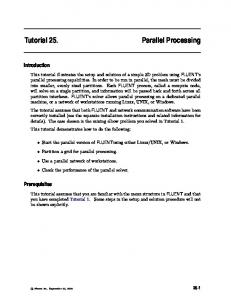
4.3 Tiles for parallel decoding Tiles are advantageous for parallel decoding purpose when compared to slices or WPPs. In the example shown in Figure 13, a picture is divided into 4 sub-pictures of equal size. With tiles, the picture can be divided into 2x2 sub-pictures. However, with regular slices for example, the picture would need to be divided into 1x4 sub-pictures. Sub-picture partitioning using tiles are apparently advantageous in the follows aspects: 1) sub-picture width is only half of picture width, which cuts the line buffer size by half. 2) fewer number of sub-picture boundaries in terms of pixels (one vertical and horizontal vs. three horizontal sub-picture boundaries as shown in Figure 13) leads to better quality; for instance, for 1080 HD (1920x1088), tiles would result in 3008 pixel boundaries versus 5760 pixel boundaries for slices. 3) tiles are independent which minimizes cross-core communications; only reference picture data is shared among cores. 4) cores can be simply replicated to build multi-core solutions without need of additional design validation efforts to verify crosscore interconnections.
Proc. of SPIE Vol. 8499 849910-10 Downloaded From: http://proceedings.spiedigitallibrary.org/ on 10/23/2014 Terms of Use: http://spiedl.org/terms
Sub-picture boundaries
Sub-pic0 Sub-pic0
Sub-pic1
Sub-pic1 Sub-pic2
Sub-pic2
Sub-pic3
Sub-picture partitioning using tiles
Sub-pic3 Sub-picture partitioning using slices
Figure 13: Sub-picture partitioning
To make tiles work for parallel decoding processing on multi-core platform, several restrictions would need to be imposed on the bitstream so that a decoder can rely on built-in parallel processing features to dispatch the bitstream to multi-core simultaneously for parallel decoding. Those restrictions are:
1. It should be mandated to divide an Ultra-HD picture into a number of uniformly spaced tiles so that pixel-rate balancing is guaranteed for multiple core platforms. Tile widths should not exceed single core line buffer width partitioning so that the single-core decoder line buffer does not need to be increased when single cores are replicated to build up multi-core decoder
2. Tiles should be independent for minimizing cross-core data communication. Only de-blocking filter, Sample Adaptive Offset (SAO), Adaptive Loop Filter (ALF) can cross tile boundaries. 3. Slices, entropy slices and WPPs, if present, should be contained within tiles and cannot cross tile boundaries 4. Tile sub-stream entries in bitstream are signaled in at picture level, so that a multi-core decoder can dispatch sub-streams to cores in parallel. With uniformly spaced tiles and restrictions above, HEVC potentially enables a cost-effective way of building multicore platforms for supporting Ultra-HD real-time decoding. As shown in Figure 14, a 8kx4k at 30 fps decoder can be built by simply replicating the 4kx2k at 30 fps single core decoder four times, and adding a sub-picture boundary processing core to perform e.g. de-blocking filter, Sample Adaptive Offset (SAO), Adaptive Loop Filter (ALF) along tile boundaries. Sub-picture boundary processing core
Single core decoder (slices, ES, WPP) Up to e.g. 4kx2k at 30fps
Single core decoder1 (slices, ES, WPP)
Single core decoder2 (slices, ES, WPP)
Single core decoder3 (slices, ES, WPP)
Single core decoder4 (slices, ES, WPP)
Up to e.g. 8kx4k at 30fps
Figure 14: Building a multi-core decoder by replicating single core decoders
5. CONCLUSIONS Parallelism and high throughput processing continue to be of critical importance as the demand for larger frame rates and resolutions continues to grow. These requirements were considered during the development of the latest video coding standard HEVC. This paper discusses various methods in which the throughput of the video codec has been
Proc. of SPIE Vol. 8499 849910-11 Downloaded From: http://proceedings.spiedigitallibrary.org/ on 10/23/2014 Terms of Use: http://spiedl.org/terms
improved including at the low level in the CABAC entropy coder, at the high level with tiles, and at the encoder with parallel merge/skip. By accounting for these implementation challenges, HEVC can deliver both the coding efficiency and the throughput required to support the high bit-rates and pixel-rate of future video content.
6. REFERENCES [1] F. Bossen, “JCTVC-I1100: Common test conditions and software reference configurations,” Joint Collaborative Team on Video Coding (JCT-VC), May 2012 [2] B. Bross, W.-J. Han, J.-R. Ohm, G. J. Sullivan, T. Wiegand “JCTVC-I1003: High Efficiency Video Coding (HEVC) text specification draft 7,” Joint Collaborative Team on Video Coding (JCT-VC), May 2012 [3] “Recommendation ITU-T H.264: Advanced Video Coding for Generic Audiovisual Services,” Tech. Rep., ITU-T, 2003 [4] D. Marpe, H. Schwarz, and T. Wiegand, “Context-based adaptive binary arithmetic coding in the H.264/AVC video compression standard,” IEEE Trans. on CSVT, vol. 13, no. 7, pp. 620– 636, July 2003 [5] M. Winken, S. BoBe, B. Bross, P. Helle, T. Hinz, H. Kirchhoffer, H. Lakshman, D. Marpe, S. Oudin, M. PreiB, H. Schwarz, M. Siekmann, K. Suhring, and T. Wiegand, “JCTVC-A116: Description of video coding technology proposal by Fraunhofer HHI,” Joint Collaborative Team on Video Coding (JCT-VC), April 2010 [6] T. Nguyen, D Marpe, H. Schwarz, and T. Wiegand, “JCTVC-D061: CE11: Evaluation of Transform Coding tools in HE configuration,” Joint Collaborative Team on Video Coding (JCT-VC), Jan. 2011 [7] V. Sze and M. Budagavi, “JCTVC-C227: Parallelization of HHI TRANSFORM CODING,” Joint Collaborative Team on Video Coding (JCT-VC), Oct. 2010 [8] A. Cheung and W. Lui, “JCTVC-D260: Parallel processing friendly simplified context selection of significance map,” Joint Collaborative Team on Video Coding (JCT-VC), Jan. 2011 [9] V. Sze and M. Budagavi, “JCTVC-F129: CE11: Parallelization of HHI TRANSFORM CODING Fixed Diagonal Scan,” Joint Collaborative Team on Video Coding (JCT-VC), July 2011 [10] S. Kumakura, T. Fukushima, “JCTVC-I0296: Non-CE3: Simplified context derivation for significance map,” Joint Collaborative Team on Video Coding (JCT-VC), April 2012 [11] M. Budagavi and M. U. Demircin, “JCTVC-B088: Parallel Context Processing techniques for high coding efficiency entropy coding in HEVC,” Joint Collaborative Team on Video Coding (JCT-VC), July 2010 [12] M. Budagavi, “JCTVC-C062: TE8: TI parallel context processing (PCP) proposal,” Joint Collaborative Team on Video Coding (JCT-VC), Oct. 2010 [13] J. Sole, R. Joshi, and M. Karczewicz, “JCTVC-E338: CE11: Parallel Context Processing for the significance map in high coding efficiency,” Joint Collaborative Team on Video Coding (JCT-VC), March 2011 [14] T. Nguyen, “JCTVC-E253: CE11: Coding of transform coefficient levels with Golomb-Rice codes,” Joint Collaborative Team on Video Coding (JCT-VC), March 2011 [15] V. Sze and M. Budagavi, “JCTVC-F130: Parallel Context Processing of Coefficient Level,” Joint Collaborative Team on Video Coding (JCTVC), July 2011 [16] J. Chen, W. J. Chien, R. Joshi, J. Sole, and M. Karczewicz, “JCTVCH0554: Non-CE1: throughput improvement on CABAC coefficients level coding,” Joint Collaborative Team on Video Coding (JCT-VC), Feb. 2012 [17] M. Zhou, “JCTVC-F069: Parallelized merge/skip mode for HEVC,” Joint Collaborative Team on Video Coding (JCT-VC), July 2011 [18] M. Zhou, “JCTVC-G085: CE9: Test results on parallel merge/skip mode,” Joint Collaborative Team on Video Coding (JCT-VC), Nov. 2011 [19] M. Zhou, “JCTVC-H0082: AHG10: Configurable and CU-group level parallel merge/skip,” Joint Collaborative Team on Video Coding (JCT-VC), Feb. 2012 [20] K. Olukotun, Intel CPU trends [21] A. Fuldseth, M. Horowitz, S. Xu, A. Segall. M. Zhou, “JCTVC-F335: Tiles,” Joint Collaborative Team on Video Coding (JCT-VC), July 2011 [22] C. Gordon, F. Henry, S. Pateux, “JCTVC-F274: Wavefront Parallel Processing for HEVC Encoding and Decoding,” Joint Collaborative Team on Video Coding (JCTVC), July 2011 [23] K. Misra, J. Zhao, A. Segall, “JCTVC-C256: New results for entropy slices for highly parallel coding”, Joint Collaborative Team on Video Coding (JCTVC), Oct. 2010 [24] M. Zhou, “JCTVC-B062: Sub-picture based raster scanning coding order for HEVC UHD video coding,” Joint Collaborative Team on Video Coding (JCT-VC), July 2011
Proc. of SPIE Vol. 8499 849910-12 Downloaded From: http://proceedings.spiedigitallibrary.org/ on 10/23/2014 Terms of Use: http://spiedl.org/terms
[25] M. Horowitz and S. Xu, “JCTVC-D378: Generalized slices,” Joint Collaborative Team on Video Coding (JCT-VC) Jan. 2011 [26] A. Fuldseth, “JCTVC-D227: Replacing slices with tiles for high level parallelism,” Joint Collaborative Team on Video Coding (JCT-VC) Jan. 2011
Proc. of SPIE Vol. 8499 849910-13 Downloaded From: http://proceedings.spiedigitallibrary.org/ on 10/23/2014 Terms of Use: http://spiedl.org/terms