812
IEEE TRANSACTIONS ON INFORMATION FORENSICS AND SECURITY, VOL. 4, NO. 4, DECEMBER 2009
Parallelizing Iris Recognition Ryan N. Rakvic, Member, IEEE, Bradley J. Ulis, Randy P. Broussard, Robert W. Ives, Senior Member, IEEE, and Neil Steiner
Abstract—Iris recognition is one of the most accurate biometric methods in use today. However, the iris recognition algorithms are currently implemented on general purpose sequential processing systems, such as generic central processing units (CPUs). In this work, we present a more direct and parallel processing alternative using field-programmable gate arrays (FPGAs), offering an opportunity to increase speed and potentially alter the form factor of the resulting system. Within the means of this project, the most time-consuming operations of a modern iris recognition algorithm are deconstructed and directly parallelized. In particular, portions of iris segmentation, template creation, and template matching are parallelized on an FPGA-based system, with a demonstrated speedup of 9.6, 324, and 19 times, respectively, when compared to a state-of-the-art CPU-based version. Furthermore, the parallel algorithm on our FPGA also greatly outperforms our calculated theoretical best Intel CPU design. Finally, on a state-of-the-art FPGA, we conclude that a full implementation of a very fast iris recognition algorithm is more than feasible, providing a potential small form-factor solution. Index Terms—Biometrics, field-programmable gate arrays (FPGAs), iris recognition, parallel computing.
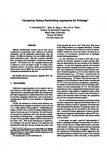
I. INTRODUCTION RIS recognition stands out as one of the most accurate biometric methods in use today. Currently, iris recognition algorithms are deployed globally in a variety of systems ranging from personal computers to portable iris scanners. The overall performance, in terms of size, shape, speed, power, and accuracy, of these systems have become of great interest. Currently, iris recognition algorithms are deployed globally in a variety of systems ranging from personal computers to portable iris scanners. These systems use central processing unit (CPU)-based systems for which the algorithm was originally designed. CPU-based systems are considered general purpose machines, designed for all types of applications. Therefore, CPU-based systems are known as sequential processing devices. Fig. 1 illustrates a simple processor pipeline. Instructions are first fetched, decoded, and finally executed by arithmetic logic units, or ALUs. State-of-the-art processors contain more
I
Manuscript received February 16, 2009; revised July 23, 2009. First published September 22, 2009; current version published November 18, 2009. This work was supported in part by the Department of Defense and in part by the Information Sciences Institute-East. The associate editor coordinating the review of this manuscript and approving it for publication was Prof. Vijaya Kumar Bhagavatula. R. N. Rakvic, B. J. Ulis, R. P. Broussard, and R. W. Ives are with the United States Naval Academy, Annapolis, MD 21402 USA (e-mail:
[email protected];
[email protected];
[email protected];
[email protected]). N. Steiner is with the University of Southern California’s Information Sciences Institute, Arlington, VA 22203 USA (e-mail:
[email protected]). Color versions of one or more of the figures in this paper are available online at http://ieeexplore.ieee.org. Digital Object Identifier 10.1109/TIFS.2009.2032012
Fig. 1. Simple processor pipeline with four ALUs.
than one ALU. Therefore, multiple instructions can be executed in parallel. However, modern processors are limited in the number of ALUs they possess, and most of today’s CPUs do not have more than four, as illustrated in Fig. 1. As pointed out in previous papers [24]–[26], this method of processing for which the recognition algorithm is currently designed is inefficient since parts of the iris recognition algorithm can be greatly parallelized. The goal of this research is to find and exploit potential parallelism within iris recognition algorithms. Field-programmable gate arrays (FPGAs) are complex programmable logic devices that are essentially a “blank slate” integrated circuit that can be programmed with nearly any parallel logic function. They are fully customizable and the designer can prototype, simulate, and implement a parallel logic function without the costly process of having a new integrated circuit manufactured from scratch. By programming the hardware directly, performance and energy consumption can be improved while the size and form factor of the system can be altered. The focus of this research is on parallelizing key portions of the iris recognition algorithm using an FPGA. This work demonstrates this by making the following contributions: 1) Introduction and calculation of the theoretical best performance of CPU-based machines executing key components of an iris recognition algorithm. 2) Measurements of CPU performance of key components of an iris recognition algorithm on a state-of-the-art computer. 3) Deconstruction and novel parallelization of three key iris recognition components: 1) Iris segmentation using local kurtosis, 2) iris template creation via filtering, and 3) template matching via hamming distance. 4) Evaluation of the benefits of parallelization in terms of performance and size.
1556-6013/$26.00 © 2009 IEEE Authorized licensed use limited to: US Naval Academy. Downloaded on June 25,2010 at 18:41:21 UTC from IEEE Xplore. Restrictions apply.
RAKVIC et al.: PARALLELIZING IRIS RECOGNITION
Fig. 2. Template creation.
II. RIDGE ENERGY DETECTION IRIS RECOGNITION ALGORITHM The first and most popular iris recognition algorithm was introduced by pioneer Dr. J. Daugman [1], [16]. This patented algorithm is not available for open use, so an alternative for research purposes can be found in the implementation created by L. Masek [17]. There are also many other proposed methods [18]–[22] to perform iris recognition. Ives et al. have developed an alternate iris recognition algorithm, referred to as the ridge energy direction (RED) algorithm [2] that will be the focus of this work. The RED algorithm has been shown to have comparable performance to state-of-the-art algorithms that have been previously published [2]. In particular, the three parts of the RED algorithm have been fine-tuned to produce highly accurate iris recognition achieving 99.999% and 99.603% accuracy on the Bath2000 [28] and CASIA I [29] databases, respectively. In comparison, Masek’s implementation [17] of Daugman’s algorithm resulted in 99.526% and 99.630% accuracy on the same Bath2000 and CASIA I databases, respectively. The steps of the RED algorithm are illustrated in Fig. 2. One of the first steps in preprocessing the image before extracting its unique features is to segment the iris from the rest of the image. Several means have been proposed to perform this segmentation [4]–[8], but this algorithm utilizes a different approach using local statistics [15] to aid in determining the outer boundary of the iris. After iris segmentation, feature extraction is performed based on directional filters. The iris is then transformed to polar coordinates, and the iris image is histogram equalized and then processed by each of two different directional filters (vertically and horizontally oriented). At every pixel location, the identity of the directional filter which provides the largest value of output is recorded, and represented with a single bit, thus generating a template. Templates are then matched using fractional Hamming Distance as the measure of closeness. We will now highlight three main components of the RED algorithm that help dictate performance of the overall algorithm: 1) segmentation of the outer boundary of the iris; 2) iris template generation; and 3) iris template matching. A. Iris Segmentation With Local Kurtosis After determining the location of the pupil, the center of the pupil is used as a reference for unwrapping the iris image to
813
polar coordinates (50 rows by 180 columns). The center of the limbic boundary is not typically the same as the center of the pupil, so we consider a number of possible centers for the limbic boundary: the pupil center and the pupil center shifted by small increments to the left and right. Note that when unwrapping the iris from the correct center of the outer boundary, in the unwrapped image the outer boundary will appear as a horizontal line. For each of these unwrapped images, we compute the local kurtosis [9] in 3 3 neighborhoods of each pixel. In the resulting image, we observe that the values near the limbic boundary are relatively stable in small neighborhoods, compared with the appearance in the sclera and in the interior of the iris. Therefore, to create binary images, we assign a value of 1 (white) to locations for which kurtosis values within a 3 3 neighborhood are nearly constant. The correct center of the outer boundary will appear in the unwrapped image that has the longest nearly horizontal white border. Calculating the kurtosis repeatedly to aid with iris segmentation is a time-consuming portion of the RED algorithm, and hence we focus on it in this research. B. Template Generation via Filtering After determining the inner and outer boundaries and center of the pupil, the iris is again transformed into polar coordinates with the center of the pupil as the point of reference, into a 120 row by 180 column image. In this process, the radial extent of the iris is normalized in order to account for pupil dilation. Each row in the unwrapped iris image represents an annular region surrounding the pupil, and the columns represent radial information. Next, we consider the “energy” of the unwrapped iris image after an adaptive histogram equalization. Here, energy loosely refers to the prominence (pixel values) of the ridges that appear in the histogram equalized image: higher value reflects higher energy. This “energy” image is passed into each of two different directional filters (a vertical filter and a horizontal filter). These filters are used to indicate the presence of strong ridges, and the orientation of these ridges. At every pixel location in the filtered image, the filter which provides the largest value of output is recorded and encoded with one bit to represent the identity of this directional filter. The iris image is thus transformed into a one-bit template that is the same size as the image in polar coordinates (120 rows by 180 columns). A template mask is also created during this filtering process. If both filter output values are not above a certain threshold, then a mask bit is cleared for that particular pixel location. The template mask is used to identify pixel locations where neither vertical nor horizontal directions are identified. C. Template Matching via Hamming Distance The template can now be compared to a stored template using the fractional Hamming distance as the measure of closeness (see Fig. 3). The fractional Hamming distance between two templates is defined as
(1) operator is the EXCLUSIVE OR operation to detect The disagreement between the pairs of bits that represent the directions in the two templates, represents the binary AND function, and masks A and B identify the values in each template
Authorized licensed use limited to: US Naval Academy. Downloaded on June 25,2010 at 18:41:21 UTC from IEEE Xplore. Restrictions apply.
814
IEEE TRANSACTIONS ON INFORMATION FORENSICS AND SECURITY, VOL. 4, NO. 4, DECEMBER 2009
Fig. 3. New template is compared with each template stored in a database.
that are not corrupted by artifacts such as eyelids/eyelashes and specularities. The denominator of (1) ensures that only the bits that matter are included in the calculation, after artifacts are discounted. Rotation (due to head-tilt) mismatch between irises is handled with left–right shifts of the coded one-bit template to determine the minimum Hamming distance. The lower the HD result, the greater the match between the two irises being compared. The fractional Hamming distance between two templates is compared to a predetermined threshold value and a match or nonmatch declaration is made. The time-consumption of template matching can greatly affect speed performance, since it is tied to the size of the database that it is being matched against. III. FPGA PARALLELIZATION FPGAs are complex programmable logic devices that are essentially a “blank slate” integrated circuit that can be programmed with nearly any parallel logic function. They are fully customizable and the designer can prototype, simulate, and implement a parallel logic function without the costly process of having a new integrated circuit manufactured from scratch. FPGAs are commonly programmed via VHSIC Hardware Description Language (VHDL). VHDL statements are inherently parallel, not sequential. VHDL allows the programmer to dictate the type of hardware that is synthesized on an FPGA. For example, if you would like to have 2048 XOR logic gates that execute in parallel, then you program this directly in the VHDL code. In this research, we will demonstrate a parallelization of three major components of the RED iris recognition algorithm: 1) iris segmentation with kurtosis, 2) template creation via filtering, and 3) template matching via hamming distance. We will conclude this section with a brief discussion of future parallelizations. A. Iris Segmentation via Kurtosis As stated previously, kurtosis is used to aid with iris segmentation. In the RED algorithm, repeated kurtosis calculations on 5 5 elements are made across the size of an image. Kurtosis is often used in probability theory to represent the “peakedness” of the probability distribution of a real-valued random variable [10]. Intuitively it is known as a measure of the volatility of volatility. It is described by the following mathematical
function: (2)
where represents the number of elements (25) for this calculation, represents the mean for those elements, and is the random variable representing their actual values. Fig. 4 introduces the C++ code for the kurtosis function, and ave represents the average of the block of code. It is calculated inside a FOR loop, where the loop cycles through a 5 5 matrix and the index variable is, therefore, 25. Notice the sequential nature, since each matrix element is added one by one. The next FOR loop contains the calculations for variance and fourth moment by using the calculated ave above. For example, a difference is first calculated followed by four multiplications and a summation to create the fourth moment. This process is also repeated 25 times sequentially. After the loop, final computation for the kurtosis function is performed with three divisions and a multiplication. The Intel Assembly code for this calculation is shown in Fig. 4. In general, eight sequential instructions are required to perform the loop overhead, following that each calculation requires multiple instructions. For example, the fourth moment calculation requires three floating point multiplications. Floating point multiplications typically require dozens of processor cycles to execute. The total number of assembly instructions required to perform this kurtosis calculation is 741, of which 259 are floating point instructions. Instruction execution bandwidth for a processor is limited by the number of functional units that it contains. For example, a processor with four ALU functional units can maximally execute four instructions per cycle. Therefore, in theory, a processor executing four instructions per cycle at 4 GHz can maximally execute 16-G instructions per second. Therefore, assuming a processor speed of 4 GHz, four ALUs, and four instructions executed per cycle, the total theoretical best case time is 46.3 ns
We have successfully parallelized the kurtosis function in VHDL. Illustrated in Fig. 4 is our VHDL code for the kurtosis function. As can be seen, it is also contained in a FOR loop that
Authorized licensed use limited to: US Naval Academy. Downloaded on June 25,2010 at 18:41:21 UTC from IEEE Xplore. Restrictions apply.
RAKVIC et al.: PARALLELIZING IRIS RECOGNITION
815
Fig. 4. Kurtosis algorithm in (a) C++, (b) Intel Assembly, and (c) VHDL.
appears to be sequential. Each iteration however of a FOR loop is implemented in parallel. Therefore, all 25 iterations of the loop are performed concurrently. Due to the inherent multiplication required by the kurtosis algorithm, this compilation and synthesis results in an implementation that utilizes the limited on chip multipliers. We will discuss the hardware usage of our algorithm in the following section.
In addition to the previously described “intra” kurtosis function parallelization, “inter” kurtosis function parallelization can also be computed. Here, “inter” kurtosis function parallelization means computing multiple kurtosis function calculations simultaneously. We synthesized a different hardware version consisting of two kurtosis algorithms executing in parallel to demonstrate feasibility and potential. We will present results
Authorized licensed use limited to: US Naval Academy. Downloaded on June 25,2010 at 18:41:21 UTC from IEEE Xplore. Restrictions apply.
816
IEEE TRANSACTIONS ON INFORMATION FORENSICS AND SECURITY, VOL. 4, NO. 4, DECEMBER 2009
Fig. 5. (a) 9
2 9 filter computing circular convolution of top left portion of data. (b) Example two-directional filtering. (c) C++ code.
Fig. 6. Illustration of different possible digital filtering methods.
(shown below as “inter” with two copies) and discuss on-chip resource utilization in the following section. B. Template Creation via Filtering The RED iris recognition algorithm uses a digital filter to generate the iris template. The energy data passed from the iris
segmentation process is organized into a rectangular array. The rectangular array is formed into a single-holed torus to help account for edge effects. The filter passes over this periodic array taking in 81 (9 9) values at a time (note, in [2], 11 11 is used, although 9 9 provides very similar results). More specifically, the result is computed by first multiplying each filter value by
Authorized licensed use limited to: US Naval Academy. Downloaded on June 25,2010 at 18:41:21 UTC from IEEE Xplore. Restrictions apply.
RAKVIC et al.: PARALLELIZING IRIS RECOGNITION
the corresponding input data value. Then a summation is performed, and the result is stored in a memory location that corresponds to the centroid of the filter. This process repeats for each pixel in the input data, stepping right, column-by-column, and down, row-by-row, until the filtering is complete, as shown in Fig. 5(a). Finally, the template is generated by comparing the results of two different directional filters (horizontal and vertical) and writing a single bit that represents the filter with the highest output at the equivalent location. The output of each filter is compared and for each pixel, a “1” is assigned for strong vertical content or a “0” for strong horizontal content. These bits are concatenated to form a bit vector unique to the “iris signal” that conveys the identifiable information. This final step is demonstrated in Fig. 5(b). In this example, the two filters are represented in the middle of the diagram, while the image data is on the left. In this example, the filter provides higher output with the vertical filter, and hence a 1 bit is stored for this particular pixel location. As described in prior art [3], there are three methods to compute a digital filter, as shown in Fig. 6. The first method uses a general purpose processor to compute the digital filter via software, executing a single instruction, and hence byte (shown as 1) at a time. This approach is acceptable if the digital filter is small; however, as the digital filter and data set to be filtered increases, the computational load rises exponentially. The second approach is to develop hardware specifically designed to compute the digital filter but by first loading all the data (all 81 bytes, illustrated 81) into an array of computing elements. By loading the data first (buffering the data into the hardware), this approach is similar to the sequential general purpose processor method due to overhead. Only partial calculations can be computed until the entire kernel is filled. The third and final approach is to redefine the filtering as a parallel process, allowing the hardware to take in a single byte of data and compute the maximum influence that data would have on the final results. The method is a truly parallel process and minimizes the need for overhead and buffering that other sequential processes use. Throughout this paper, the parallel method of approach will be investigated and compared in detail to sequential methods. Parallelizing the RED algorithm filtering can be done simply by doing the obvious—calculating the result of both filters at the same time and computing the single bit representation in the template simultaneously. Unfortunately, while this straightforward approach appears to cut out a large amount of intermediate memory, it in fact suffers from a very serious memory bottleneck. The energy data to compute a single result must first be fully loaded into a hardware representation of each filter. Assuming the filters could compute the final template bit in a single clock cycle, each filter must read 81 different 8-bit values of energy data before any filtering can be done. Therefore, a straightforward approach to digital filtering in hardware will suffer due to the overhead associated with waiting for data to be localized near the computing elements. In this case, since the computing elements are idle until the 81 data values are loaded, the process is fundamentally sequential much like the general purpose processor. Consequently, a straightforward filtering in hardware is inherently not parallel with a single bank of memory holding all the energy data. To parallelize the digital filter, the memory itself must be parallelized. A possible but impractical option to parallelize the
817
straightforward digital filter would be to create an 81 ported block of memory or 81 parallel blocks of memory that could supply all energy data to both filters in a single step. Either case would exceed the memory resources of even the most massive FPGAs while also potentially creating interconnect issues. Furthermore, even if the memory issue was inconsequential to the straightforward digital filtering, there is no way around the overhead associated with needing at least 81 energy data values and at least nine more properly arranged to step in either the horizontal or vertical directions. There is an alternative way to accomplish the digital filtering that also offers greater opportunity for parallelization while also reducing the bandwidth requirements on memory. Our digital filtering is a commutative mathematical operation of the form or
The resulting function is either function filtered with or filtered with . This concept is critical in modifying the digital filtering algorithm so that it can more easily be implemented in hardware. Typically, the filter is streamed overtop the input data, but for parallelizing purposes, the input data will be streamed over the centroid of the filter. This approach is analogous to dropping the energy data onto the centroid of the filter and computing the partial product of all results within scope. Commuting the filtering eliminates the overhead associated with buffering all the energy data into the filter to calculate a single result and greatly simplifies the hardware implementation (see Fig. 7). The parallelized digital filters maximize the computations for any single 8 bits of energy data so that input buffering is kept at an absolute minimum while also offering quite a bit of freedom with regard to the form of the resulting data. The parallelized digital filter computes the partial products and writes the results to memory into the appropriately wrapped memory locations. While outside the scope of this paper, it is likely possible to compute the partial results directly into the finalized template, totally eliminating the need for intermediate memory but that is left to the discretion of the engineer to handle the filters in whatever way best fits the application. The RED algorithm digital filtering is designed and implemented in VHDL software. The parallel hardware filter consists of 81 accumulator cores arranged in a nine by nine array to represent the original filter. The accumulators are grouped within the array by row since the energy data from the segmentation process (or most other common process) emerges left to right, top to bottom, easing the memory access as the filter array steps through the incoming data. Each row is accommodated with a block of simple dual ported ram to support all the simultaneous reading and writing needs of the accumulator core row. Also among each row is a multiplexer to narrow the control of memory to a single accumulator core and a row controller to grant any accumulator within the row memory control and issue the proper control signals to the row’s accumulator cores. Finally, the array is fitted with a first-in-first-out (FIFO) memory buffer to ease incoming data and a comparator module that judges which filter had the highest output and issues the appropriate bit to the finalized template for matching. The full
Authorized licensed use limited to: US Naval Academy. Downloaded on June 25,2010 at 18:41:21 UTC from IEEE Xplore. Restrictions apply.
818
IEEE TRANSACTIONS ON INFORMATION FORENSICS AND SECURITY, VOL. 4, NO. 4, DECEMBER 2009
Fig. 7. 9
2 9 commutated circular convolution.
Fig. 8. Template generation VHDL system block diagram.
system is shown in Fig. 8. Due to the complexity, the VHDL code for this portion of our parallelization is not shown here. C. Template Matching via Hamming Distance The focus of this section is on parallelizing the template matching portion of the algorithm. The template matching portion of the algorithm is important due to its repeated execution (depending on the number of iris comparisons necessary). Illustrated in Fig. 9 is optimized C++ code for computing the fractional HD between two templates. In order to help count the number of 1’s in a binary number, the code contains a lookup table (Value). The lookup table holds the number of 1’s that are in that particular 16 bit number. This lookup table is small enough to fit into the cache and has been shown to execute faster because it requires less assembly instructions than a recursive or loop-based method. We would like to highlight the sequential nature of this code. For example, since the XOR function is performed 32 bits at a time, a loop (FOR loop denoted below) is necessary. Since it is computing 2048 bits, this loop is executed 64 times. Also, note that the XOR and AND computations are also performed sequentially. These instructions could be scheduled to execute in parallel, but a modern CPU has a limited number of functional units, therefore limiting the amount of parallel execution. Finally, a score is computed as a ratio of the number of differ-
ences between the templates to the total number of bits that are not masked. Illustrated in Fig. 9 is the associated assembly code created for the hamming distance calculation. The code is compiled for a Xeon Processor, and hence IA-32 assembly code is produced [11]. For each C++ computation, there are at least five assembly language instructions required. For example, for the AND computation that is in C++ code, there are four MOV instructions and one AND instruction. The MOV instructions are required to move data in and out of registers in preparation for the logical instruction. This AND instruction is a 32-bitwise computation performed by an ALU functional unit in the processor. Illustrated in Fig. 10 are the assembly instructions that are required for the loop instruction. Loop instructions require the aforementioned overhead. For each iteration of the loop, there is required a total of 38 assembly instructions. As stated above, this code requires 64 loops to perform a template match. Therefore, according to the following formula, a template match on a perfect 4-GHz 4 IPC microprocessor is 151 ns per match:
Ideally, if 2048 matching elements could fit onto the FPGA, then the iris recognition algorithm could be many times faster. Fig. 11 illustrates our VHDL code that implements the HD cal-
Authorized licensed use limited to: US Naval Academy. Downloaded on June 25,2010 at 18:41:21 UTC from IEEE Xplore. Restrictions apply.
RAKVIC et al.: PARALLELIZING IRIS RECOGNITION
819
Fig. 9. Template matching C++ and intel assembly.
Fig. 10. Overhead assembly instructions for loop.
culation. Here we perform the same function as the aforementioned C++ code. However, we are doing this computation completely in parallel. There are 2048 XOR gates and 4096 AND gates required for this computation. In addition, adders are required for summing and calculating the score. The iris templates must be stored either in memory on the FPGA or off-chip. In one instance of our implementation, we have implemented a 2048-bit-wide memory in VHDL. We have added this to our code to verify that a small database can be stored on chip. One of the two templates compared is received from this dual-ported 2048-bit-wide single cycle cache implemented on our FPGA. Therefore, once per clock cycle, a 2048-bit vector is fetched from on-chip memory, and the HD calculation is performed. We have successfully implemented
and tested the HD calculation with and without a memory device. D. Future Topics Segmentation in iris recognition algorithms requires substantial computer vision and digital signal processing techniques to accurately detect the inner and outer boundaries of an iris embedded in a bitmap image. Initially, finding the pupil as a large dark object in a bitmap image can be complicated by glare and eccentricities which can easily throw off an algorithm. To mitigate anomalies in the pupil, a series of dilations and erosions expand the black pupil, close gaps created by glare, and return the pupil to its original shape. After dilation and erosion, a computer can better detect the shape of the pupil as a characteristic
Authorized licensed use limited to: US Naval Academy. Downloaded on June 25,2010 at 18:41:21 UTC from IEEE Xplore. Restrictions apply.
820
IEEE TRANSACTIONS ON INFORMATION FORENSICS AND SECURITY, VOL. 4, NO. 4, DECEMBER 2009
Fig. 11. VHDL implementation of the hamming distance calculation.
Fig. 12. DE2 board from Altera Corporation.
large dark object with a center point and radius, setting it apart from eyebrows and eyelashes which remain irregular in shape. In the RED iris recognition algorithm, dilation and erosion represent approximately 30% of the segmentation execution time in software. A proposed alternative implements the dilation and erosion as an array of cells within hardware-based architecture such as an FPGA. We expect a parallel FPGA implementation to be complete after only a few clock cycles compared to the millions needed in the software dilation and erosion method. IV. RESULTS AND ANALYSIS A. Hardware Details The CPU experiment is executed on an Intel Xeon X5355 [12] workstation class machine. The processor is equipped with eight cores, 2.66-GHz clock, and an 8-MB L2 cache. While
there are eight cores available, only one core is used to perform this test, therefore allowing all cache and memory resources for the code under test. The HD code was compiled under Windows XP using the Visual Studio software suite. The code has been fully optimized to enhance performance. Additionally, millions of matches were executed to ensure that the templates are fully cached in the on-chip L2 cache. The RED algorithm optimized C++ code time is faster than some of the times reported in the literature for other commercial iris recognition implementations [27]. For example, the template matching time published in [27] is 10 m, whereas our template matching time is 383 ns. We attribute this difference to: 1) our use of a faster, more modern CPU operating at 2.66 GHz vice 300 MHz; 2) the RED algorithm is fully optimized; and 3) the RED algorithm is different from [27]. An extrapolation of the execution times of [27] on a modern computing environment at 2.66 GHz would leave it still slower, but closer to the
Authorized licensed use limited to: US Naval Academy. Downloaded on June 25,2010 at 18:41:21 UTC from IEEE Xplore. Restrictions apply.
RAKVIC et al.: PARALLELIZING IRIS RECOGNITION
821
Fig. 13. FPGA versus CPU comparison for iris match execution.
Fig. 14. FPGA hardware usage.
RED execution times. Our goal here is not to provide a direct comparison of the execution times of these two iris recognition algorithms. However, this indicates that our C++ code is a reasonable target for comparison to the FPGA performance. Furthermore, due to iris recognition algorithm similarity, one can reasonably expect similar improvements from application mapping to FPGA technology for other iris recognition algorithms. The FPGA experiment is executed on a DE2 [13] board provided by Altera Corporation. The DE2 board includes a Cyclone-II EP2C35 FPGA chip, as well as the required programming interface. The DE2 board is illustrated in Fig. 12. Although the DE2 board is utilized for this research, only the Cyclone-II chip is necessary to execute our algorithm. The Cyclone-II [14] family is designed for high-performance low-power applications. It contains over 30 000 logic elements (LEs) and over 480 000 embedded memory bits. In order to program our VHDL onto the Cyclone-II, we utilize the Altera Quartus software for implementation of our VHDL program. The Quartus suite includes compilation, synthesis, simulation, and programming environments. We are able to determine the size required of our program on the FPGA, and the resulting execution time. B. Comparisons 1) Speedup: All VHDL code is fully synthesizable and is downloaded onto our DE2 for direct hardware execution. As discussed above, our code is fully contained within a “process” statement. The process statement is only initiated when a signal in its sensitivity list changes values. The sensitivity list of our process contains the clock signal and, therefore, the code is executed once per clock cycle. In this code, the clock signal is drawn from our DE2 board which contains a 50-MHz clock. Therefore, every 20 ns, our calculation is computed. Note that
for template generation, this process takes many clock cycles, and therefore, the total time for template generation with our FPGA is 98.6 us. Fig. 13 illustrates the execution times and acceleration achieved for our implemented FPGA version on the Cyclone-II EP2C35 versus a Xeon-based C++ version. For example, the optimized C++ version takes 96.8 ns per match while the FPGA takes 20 ns per match for the kurtosis function. For the kurtosis implementation where we have two concurrent implementations on our FPGA, execution time is cut in half to 10 ns. The main result of this research is that the implementation on a modest sized FPGA is approximately 9.6, 324, and 19 times faster than a state-of-the-art CPU design for the kurtosis, filtering, and hamming distance calculations, respectively. Also illustrated in Fig. 13 are the theoretical best performances for a future Intel-based machine, assuming a 4-GHz clock speed and four ALUs. The parallel algorithm on our FPGA is approximately 2.3, 4.7, and 7.5 times faster than the theoretical best CPU design for the kurtosis, filtering, and hamming distance calculations, respectively. If Intel were to design a much faster microprocessor with a perfect compiler, it still would be orders of magnitude slower than an off-the-shelf inexpensive low-end FPGA. 2) Hardware Usage: Fig. 14 presents the utilization of the FPGA LEs for our hardware implementations. For example, our implementation of the “inter” with two-copy kurtosis function parallelization utilizes 9% of our Cyclone-II FPGA. We found that the single-copy version utilized 0% of the LEs, but exhausted all of the on-chip multipliers. Only 9% of our chip is utilized by the second kurtosis function implementation. For the template generation code, a much more parallel and hardware intensive approach is utilized, therefore extending the
Authorized licensed use limited to: US Naval Academy. Downloaded on June 25,2010 at 18:41:21 UTC from IEEE Xplore. Restrictions apply.
822
IEEE TRANSACTIONS ON INFORMATION FORENSICS AND SECURITY, VOL. 4, NO. 4, DECEMBER 2009
usage of the Cyclone-II chip. As illustrated, the template generation consumes 71% of the Cyclone-II LEs, and 17% of memory bit availability. Our implementation of the hamming distance algorithm utilizes 73% of our Cyclone-II FPGA. In terms of on-chip memory usage, one of the two templates compared is stored in this dual-ported 2048-bit-wide single-cycle cache implemented on our Cyclone-II FPGA. Each stored template consumes 0.7% of on-chip memory. We have added this to our code to verify that a small database of approximately 230 can be stored on chip. 3) Projections and Other Issues: The Cyclone-II is not a state-of-the-art design. A projection of the performance and hardware usage of a state-of-the-art Stratix IV at 500-MHz [23] FPGA is given in Figs. 13 and 14, respectively. For example, given traditional scaling of FPGAs, we anticipate that a Stratix-IV at 500 MHz would be able to perform the hamming distance computation in only 2 ns. Therefore, a state-of-the-art FPGA can outperform a state-of-the-art computer by 90, 1500, and 190 times faster than a state-of-the-art CPU design for the kurtosis, filtering, and hamming distance calculations, respectively. The hardware usage of the Stratix-IV for our three components is also drastically reduced. For example, for the kurtosis function, parallelism can be increased since each 5 5 matrix computation will now only consume less than 1% of the chip. All told, the three algorithms now only consume 0.9%, 7.1%, and 7.3% of the Stratix-IV for kurtosis, filtering, and hamming distance calculations, respectively. Therefore, a full implementation of a very fast iris recognition algorithm is more than feasible. On-chip memory for the Stratix-IV is also much larger with 22.4 Mbits of on-chip storage [23]. This is important for both iris template storage and digital filtering. For example, a database consisting of 10 000 irises can be stored on the Stratix-IV. We anticipate this storage scaling trend to continue into the future, with larger and larger database storage available. If a larger database is necessary, we propose an implementation where a DRAM chip is provided as part of the package, and the on-chip database is concurrently loaded while hamming distances are being computed. Although we have not yet empirically analyzed it, another advantage of this FPGA-based technique is power and energy reduction. FPGAs, in general, consume far less power than their CPU counterparts. A detailed study of the power and energy advantages of this implementation is outside the scope of this study and left for future work. V. CONCLUSION In this paper, we have provided novel hardware implementations which enabled us to discover that three key portions of an iris recognition algorithm can be parallelized. The main result is that the implementation on a modest sized FPGA is approximately 9.6, 324, and 19 times faster than a state-of-the-art CPU design for portions of iris segmentation, template creation, and template matching components, respectively. Furthermore, the parallel algorithm on our FPGA also greatly outperforms our calculated theoretical best Intel CPU design. Finally, on a state-of-the-art FPGA, we conclude that a full implementation of a very fast iris recognition algorithm is more than feasible, providing a potential small form-factor solution.
FPGAs have been on an impressive scaling trend over the last 10 years. They are increasing in capacity, in terms of LEs, increasing in memory, in terms of on-chip bit storage, increasing in speed, and decreasing in power consumption. We expect this scaling trend to continue in the short term and we are excited to study the different advantages of FPGAs, including power consumption. Given the commercial and military demands of an accurate, timely, and small iris recognition system, we believe an FPGA-based option presents an exciting parallel alternative for this parallel application.
REFERENCES [1] J. Daugman, “Probing the uniqueness and randomness of IrisCodes: Results from 200 billion iris pair comparisons,” Proc. IEEE, vol. 94, no. 11, pp. 1927–1935, Nov. 2006. [2] R. W. Ives, R. Broussard, L. Kennell, R. N. Rakvic, and D. Etter, “Iris recognition using the ridge energy direction (RED) algorithm,” in Proc. 42nd Ann. Asilomar Conf. Signals, Systems and Computers, Pacific Grove, CA, Nov. 2008. [3] R. N. Rakvic, B. J. Ulis, R. P. Broussard, and R. W. Ives, “Iris template generation with parallel logic,” in Proc. 42nd Ann. Asilomar Conf. Signals, Systems and Computers, Pacific Grove, CA, Nov. 2008. [4] J. Huang, Y. Wang, T. Tan, and J. Cui, “A new iris segmentation method for recognition,” in Proc. 17th Int. Conf. Pattern Recognition, Aug. 2004, vol. 3, pp. 554–557. [5] W. Kong and D. Zhang, “Accurate iris segmentation based on novel reflection and eyelash detection model,” in Proc. 2001 Int. Symp. Intelligent Multimedia, Video and Speech Processing, May 2001, pp. 263–266. [6] Q. Tian, Q. Pan, Y. Cheng, and Q. Gao, “Fast algorithm and application of Hough transform in iris segmentation,” in Proc. 2004 Int. Conf. Machine Learning and Cybernetics, Aug. 2004, vol. 7, pp. 3977–3980. [7] A. Bachoo and J. Tapamo, “A segmentation method to improve irisbased person identification,” in Proc. 7th AFRICON Conf., Sep. 2004, vol. 1, pp. 403–408. [8] J. Daugman, “High confidence visual recognition of persons by a test of statistical independence,” IEEE Trans. Pattern Anal. Mach. Intell., vol. 15, no. 11, pp. 1148–1161, Nov. 1993. [9] R. W. Ives, L. Kennell, R. Gaunt, and D. Etter, “Iris segmentation for recognition using local statistics,” in Proc. 39th Ann. Asilomar Conf. Signals, Systems and Computers, Pacific Grove, CA, 2005, pp. 859–863. [10] “Engineering Statistics Handbook” 2008 [Online]. Available: http:// www.itl.nist.gov/div898/handbook/eda/section3/eda35b.htm [11] Intel Corporation [Online]. Available: http://processorfinder.intel.com/ details.aspx?sSpec=SL9YM, Jun. 16, 2008 [12] Intel Corporation [Online]. Available: http://www.intel.com/products/ processor/manuals/index.htm, Jun. 25, 2008 [13] Altera Corporation [Online]. Available: http://www.altera.com/education/univ/materials/boards/unv-de2-board.html, Jun. 16, 2008 [14] Altera Corporation [Online]. Available: http://www.altera.com/products/devices/cyclone2/cy2-index.jsp, Jun. 16, 2008 [15] L. Kennell, R. W. Ives, and R. M. Gaunt, “Binary morphology and local statistics applied to iris segmentation for recognition,” presented at the 2006 IEEE Int. Conf. Image Processing, Atlanta, GA, Oct. 2006. [16] J. Daugman, “Statistical richness of visual phase information,” Int. J. Comput. Vision, vol. 45, no. 1, pp. 25–38, 2001. [17] L. Masek, “Recognition of Human Iris Patterns for Biometric Identification” Masters Thesis, The University of Western Australia, Perth, May 12, 2006 [Online]. Available: www.csse.uwa.edu.au/~pk/studentprojects/libor/LiborMasekThesis.pdf [18] R. P. Wildes, J. C. Asmuth, G. L. Green, S. C. Hsu, R. J. Kolczynski, J. R. Matey, and S. E. McBride, “A machine vision system for iris recognition,” Mach. Vision Applicat., vol. 9, pp. 1–8, 1996. [19] W. W. Boles and B. Boashash, “A human identification technique using images of the iris and wavelet transform,” IEEE Trans. Signal Process., vol. 46, no. 4, pp. 1185–1188, Apr. 1998. [20] L. Ma, T. Tan, Y. Wang, and D. Zhang, “Efficient iris recognition by characterizing key local variations,” IEEE Trans. Image Process., vol. 13, no. 6, pp. 739–750, Jun. 2004. [21] Y. Zhu, T. Tan, and Y. Wang, “Biometric personal identification based on iris patterns,” in Proc. 15th IEEE ICPR, 2000, vol. 2, pp. 801–804.
Authorized licensed use limited to: US Naval Academy. Downloaded on June 25,2010 at 18:41:21 UTC from IEEE Xplore. Restrictions apply.
RAKVIC et al.: PARALLELIZING IRIS RECOGNITION
[22] C. Park, J. Lee, M. Smith, and K. Park, “Iris-based personal authentication using a normalized directional energy feature,” in Proc. 4th Int. Conf. Audio- and Video-Based Biometric Person Authentication, Jan. 2003, pp. 224–232. [23] FPGA J. Sep. 2, 2008 [Online]. Available: http://www.fpgajournal. com/articles_2008/20080520_40nm.htm [24] R. P. Broussard, R. N. Rakvic, and R. W. Ives, “Accelerating iris template matching using commodity video graphics adapters,” in 2008 IEEE Int. Conf. Biometrics: Theory, Applications and Systems, Crystal City, VA, Sep. 2008. [25] N. A. Schmid, M. Ketkar, H. Singh, and B. Cukic, “Performance analysis of iris-based identification system at the matching score level,” IEEE Trans. Inf. Forensics Security, vol. 1, no. 2, pp. 154–168, Jun. 2006. [26] F. Hao, J. Daugman, and P. Zielinski, “A fast search algorithm for a large fuzzy database,” IEEE Trans. Inf. Forensics Security, vol. 3, no. 2, pp. 203–212, Jun. 2008. [27] J. Daugmann, “How iris recognition works,” IEEE Trans. Circuits Syst. Video Technol., vol. 14, no. 1, pp. 21–30, Jan. 2004. [28] D. M. Monro, S. Rakshit, and D. Zhang, Iris Image Database University of Bath, U.K. [Online]. Available: http://www.bath.ac.uk/elec-eng/ pages/sipg/irisweb [29] CASIA Iris Image Database [Online]. Available: http://www.sinobiometrics.com Ryan N. Rakvic (M’01) received the B.S. degree in computer engineering from the University of Michigan and the M.S. and Ph.D. degrees in computer engineering from Carnegie Mellon University. He is currently an Assistant Professor in the Electrical and Computer Engineering Department, U.S. Naval Academy, Annapolis, MD. Prior to that, he spent five years in the Computer Research Laboratory at Intel Corporation, Santa Clara, CA. During his time at Intel, he invented creative ways to increase the performance of Pentium microprocessors. More recently, he is attempting to utilize the emerging efficiency of field-programmable gate arrays (FPGAs) to outperform a general purpose microprocessor both in terms of performance and power efficiency.
Bradley J. Ulis received the B.S. degree in electrical engineering from the U.S. Naval Academy, Annapolis, MD, and is currently pursuing the M.S. degree in electrical engineering from the U.S. Naval Postgraduate School, Monterey, CA. His research interests include field-programmable gate array design and biometric signal processing.
823
Randy P. Broussard received the B.S. degree in electrical engineering from Tulane University in 1986, the M.S. degree in computer engineering from Florida Institute of Technology in 1991, and the Ph.D. degree in electrical engineering from the Air Force Institute of Technology in 1997. He is currently an Assistant Professor in the Department of Systems Engineering, U.S. Naval Academy, where he teaches computer engineering, computer vision, and control systems. His research includes the areas of pattern recognition, iris recognition, neural networks, automatic target recognition, computer vision, and breast cancer detection.
Robert W. Ives (S’96–M’97–SM’03) received the B.S. degree in mathematics from the U.S. Naval Academy, Annapolis, MD, the M.S. degree in electrical engineering from the U.S. Naval Postgraduate School, Monterey, CA, and the Ph.D. degree in electrical engineering from the University of New Mexico, Albuquerque. He served 20 years in the U.S. Navy, including 5 1/2 years as a military researcher at Sandia National Laboratories, Albuquerque, and three years as an Assistant Professor in the Electrical Engineering Department, U.S. Naval Postgraduate School. After retiring from the Navy, he returned to the U.S. Naval Academy, where he is currently an Associate Professor, and is the Director of the USNA Center for Biometric Signal Processing. His research interests include biometric signal processing, image processing and compression, adaptive signal processing, information theory, and communications.
Neil Steiner received the B.A. degree from Wheaton College, the B.S.E.E. degree in electrical engineering from Illinois Institute of Technology, the M.S. degree in electrical engineering from Virginia Tech., and the Ph.D. degree in electrical engineering from Virginia Tech. in 2008. He is a Research Programmer at the University of Southern California’s Information Sciences Institute. His research interests include autonomous computing systems, hardware–software interaction, low-level FPGA configurations, and trusted integrated circuits.
Authorized licensed use limited to: US Naval Academy. Downloaded on June 25,2010 at 18:41:21 UTC from IEEE Xplore. Restrictions apply.