Parameterization of 3D Brain Structures for Statistical Shape Analysis Litao Zhu and Tianzi Jiang* National Laboratory of Pattern Recognition, Institute of Automation, Chinese Academy of Sciences, Beijing 100080, P. R. China ABSTRACT Statistical Shape Analysis (SSA) is a powerful tool for noninvasive studies of pathophysiology and diagnosis of brain diseases. It also provides a shape constraint for the segmentation of brain structures. There are two key problems in SSA: the representation of shapes and their alignments. The widely used parameterized representations are obtained by preserving angles or areas and the alignments of shapes are achieved by rotating parameter net. However, representations preserving angles or areas do not really guarantee the anatomical correspondence of brain structures. In this paper, we incorporate shape-based landmarks into parameterization of banana-like 3D brain structures to address this problem. Firstly, we get the triangulated surface of the object and extract two landmarks from the mesh, i.e. the ends of the banana-like object. Then the surface is parameterized by creating a continuous and bijective mapping from the surface to a spherical surface based on a heat conduction model. The correspondence of shapes is achieved by mapping the two landmarks to the north and south poles of the sphere and using an extracted origin orientation to select the dateline during parameterization. We apply our approach to the parameterization of lateral ventricle and a multiresolution shape representation is obtained by using the Discrete Fourier Transform. Keywords: Statistical Shape Analysis, Shape Representation, Parameterization of Shapes, Active Shape Model
1.
INTRODUCTION
Statistical Shape Analysis (SSA) is a powerful tool for noninvasive studies of pathophysiology and diagnosis of brain diseases1-7. It is a key component of the emerging discipline called Computational Anatomy8-9. The population-based shape analysis not only reveals the difference between the healthy and diseased subjects, but also provides the dynamic variations of the patients’ brain structures over time5-7. At the same time, Statistical Shape Analysis also provides a shape constraint for the segmentation of brain structures, such as Active Shape Model (ASM) and Active Appearance Model (AAM) introduced by Cootes et al.10-13. There are two key problems in SSA: the representation of shapes and their alignments. The shape model should effectively describe the global and local shape information of the objects, while establish the correspondence of different samples. It is very important for statistical analysis to obtain the correct correspondence of the structures, otherwise the shape variation due to age, gender, genetics or disease will be submerged in the variation caused by bad correspondence. The generally used shape models include the surface Point Distribution Model (PDM) (or Polygonal Surface Model) 1415 , the Parameterized Surface Model16-18, and the Skeleton (or Medial) Model19-21. 1.
*
The Point Distribution Model is a set of points on the object’s surface and their connectivity, such as the widely used triangulated mesh. It is easily extracted from the binary or grey-level image using Marching Cube algorithm or other similar methods and the correspondence can be established by using landmarks. However, PDM can not efficiently describe the shape information, especially the global shape information, because of its large number of vertexes. Further more, it is extremely time-consuming to select dense landmarks manually in 3D. In practice, the
Email:
[email protected] and
[email protected]
correspondence of objects in PDM is generally established from a few manually or automatically selected landmarks22-23 or using non-rigid registration (warping) approach14. 2.
The Parameterized Surface Model is achieved by mapping the surface of object to a spherical surface or a cylinder, which can be further transformed into the Spherical Harmonic Descriptor or the Fourier Descriptor16-17. It has good capability to describe both global and local shape information. Although the parameterization tries to preserve the angles or areas, it does not really guarantee the anatomical correspondence of structures. The commonly used method to establish the correspondence in parameterized surface is the rotation of the parameter net based on the shape information17 or non-rigid warping of the net using landmarks7.
3.
The Skeleton (Medial) Model is a powerful tool to describe the shape. But it is difficult to generate the Skeleton representation. The Parameterized Surface is also adopted to build the Medial Shape Model21.
Among these shape models, Parameterized Surface Model is very important because it can well represent the global and local shape information for statistical analysis and for the construction of Medial Shape Model. However, Martin’s experimental results24 show that parameterized shape representation by Spherical Harmonics (SPHARM), which adopts uniform area parameterization aligned to first order ellipsoid, obtains worse correspondence than training set based methods. The reason is that the uniform area parameterization does not really guarantee the anatomical correspondence of structures. Moreover, the computational cost of the optimization to get the uniform area parameterization limits the number of vertexes sampled on the object’s surface. In this paper, we focus on the banana-like 3D brain structures and attempt to incorporate shape-based landmarks into the Parameterization process to address the above problems. In the remainder of this paper, we first introduce the shape characters of banana-like objects, including two landmarks, the axis, and the local coordinate system for each point of the axis curve. Then the parameterization methods are described, based on automatically extracted shape characters. And the experimental results and conclusions are given in the last two sections.
2.
BANANA-LIKE OBJECTS
This paper focuses on the surface parameterization of banana-like 3D object, which is a 3D connected object with spherical topology such as the objects in Fig.1. The parameterization of banana-like objects is significant for brain image analysis because many important brain structures have banana-like shape, such as lateral ventricles, caudate nucleus, putamens, and hippocampuses. The banana-like object has two important landmarks and one axis curve as shown in Fig.2 (a). The landmarks are the two ends of the banana-like object and the axis curve is inside the object, connecting the two landmarks. At each point of the axis, there is a transverse circle, which is the object’s boundary of transverse cross-section. These landmarks, axis curve and transverse circles are the most important shape characters, which constitute the skeleton of the object. In this paper, an assumption is taken into account that the axis curve of banana-like object is an arched curve in a plane,
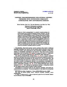
Fig. 1. Examples of banana-like 3D objects. (a) a synthetic object, (b) a left lateral ventricle segmented from the MR Image.
called axis-plane. This assumption holds true for the structures mentioned above. Based on the axis-plane, a local coordinate system can be established for each point of the axis curve as shown in Fig.2 (b), where oxyz is the axisplane coordinate system and o ' x ' y ' z ' is the local coordinate system of axis curve point o ' . The y ' -axis in the local coordinate system points from o ' to the intersection point of the transverse circle and the o ' xy -plane on the same side of the y -axis. Here the o ' xy -plane denotes the plane passing through the point o ' and parallel to oxy -plane. The intersection point will be used as the origin point for the circle, so the y ' -axis is also called origin orientation, here. In the next section, we will introduce the methods to extract these shape characters and integrate them into the surface parameterization of banana-like object.
Fig. 2. The shape characters of banana-like objects. (a) the two landmarks (the ends of the object), the axis curve (connecting two ends), and the transverse circles, which constitute the skeleton of the object; (b) the axis-plane coordinate system, oxyz , and the local coordinate system, o ' x ' y ' z ' , of axis curve point o ' , where o is the centroid of the axis curve, oxy is the axis-plane, x -axis is parallel to the line segment connecting two landmarks,
z -axis is the normal of the axis-plane; and in the local coordinate system of each axis curve point, z ' -axis is parallel to z -axis and y ' -axis is parallel to oxy -plane pointing to the point of the transverse circle on the same side of the y -axis.
3.
METHODS
The surface of a banana-like object is parameterized by creating a continuous and bijective mapping from the surface to the surface of unit sphere which is parameterized using polar coordinates as shown in Fig. 3.,
v T S1 (φ ,θ ) = ( cos(θ )cos(φ ),sin(θ ) cos(φ ),sin(φ ) ) ,0 ≤ θ < 2π , − π
2
≤φ ≤π . 2
(1)
So the parameterized surface can be represented as follows
v T f (φ ,θ ) = ( X (φ ,θ ), Y (φ ,θ ), Z (φ ,θ ) ) ,0 ≤ θ < 2π , − π
2
≤φ ≤π
2
(2)
v where φ and θ are the latitude and longitude parameters, respectively, and the value of f (φ ,θ ) is the coordinates v of the point on the banana-like surface which is mapped to the point, S1 (φ ,θ ) , on the spherical surface.
The conventional parameterization methods of the 3D objects with spherical topology attempt to obtain the mapping with minimal distortion of the surface net, such as angle preservation and area preservation17-18. In this paper, we focus on the banana-like objects and incorporate shape characters into the parameterization approach to preserve the correspondence between parameterized surfaces.
We use the 3D binary image as inputted data, which contains a single n-connected (n=6, 18, 26) banana-like object. The parameterization is implemented in four steps. Firstly, two landmarks are extracted based on geodesic distance. Secondly, the circles with the iso-value of latitude parameter, φ , and the axis curve are obtained using a heat conduction model. Thirdly, the axis-plane coordinate system is established from the axis curve using Principal Components Analysis (PCA). Then the dateline is extracted, which connects the origin points of iso-latitude circles. In the last step, each iso-latitude circle is parameterized from its origin point using the normalized arc length. Subsequently, the latitude parameter is refined using the mean distance between neighboring iso-latitude circles to get the final parameterized surface. 1.1. Two Landmarks The two ends of the banana-like object are the most important landmarks, whose correspondence should be preserved during parameterization. We use them as the latitude poles in the parameterized surface. The landmarks are extracted by finding two points with maximal geodesic distance on the surface of the object. During the detection process, the Dijkstra’s algorithm is iteratively used on the triangulated mesh of the object’s surface. In each step, the farthest vertex from the current one is found, which will be set as the new current vertex for the next search unless it returns the previous “current node” as shown in Fig.4. The initial current vertex can be given arbitrarily. The Connectivity Consistent Marching Cube (CCMC) algorithm25 is adopted to obtain the triangulated mesh from the binary image, which preserves the topology of the object by using the digital connectivity related to the 3D object to choose the surface tiling for each cube. 1.2. Iso-latitude Circles and Axis Curve Taking the two found landmarks as the north and south poles, we can obtain the latitude of each vertex on the triangulated mesh by solving a heat conduction model with the Dirichlet conditions17,
∆φ = 0, except at the two poles, where
π φnorth = + ,
(3)
2
π φsouth = − . 2
Subsequently, the iso-latitude circles are calculated from the triangulated mesh with latitude by using linear interpolation, which are treated as the transverse circles. At the two poles, the circle becomes one point. The centers of these circles constitute the axis curve, which connects the two landmarks of the object as shown in Fig.5 (a).
Fig. 3. The polar coordinates.
Fig. 4. Landmarks detection based on geodesic distance. In each step, the farthest vertex from current one is found using Dijkstra’s algorithm.
Fig. 5. Parameterization of the synthetic object. (a) Shape characters. (b) Parameter Net. The parameterization process is implemented in the following steps: 1. Detect two landmarks; 2. Get iso-latitude circles and axis curve using heat conduction model; 3. Get dateline on the surface using axis-plane coordinate system; 4. Parameterize each circle from dateline using normalize arc length; 5. Re-parameterize the latitude using the cumulative sum of the distances between each pair of neighboring iso-latitude circles.
1.3. Origin Orientation and Dateline Now that we have got the skeleton of the object, the next problem is how to create a continuous and bijective mapping from the surface to the surface of unit sphere using these extracted shape characters. The first thought is to find a dateline and use arc length to parameterize each iso-latitude circle. Different from the dateline selection in Ref.17 which chosen the path with steepest latitude ascent in each of its nodes, we adopt the origin orientation ( y ' -axis) of each point of axis curve to choose the dateline. Firstly, the axis-plane coordinate system is obtained by using PCA on the points of axis curve. We take the eigenvector of the minimal eigenvalue for the z -axis, i.e. the normal of axis-plane, and use the eigenvectors of the middle and largest eigenvalues as the y -axis and x -axis, respectively. The positive orientation of the x, y, z -axes are selected to get the right hand coordinate system as shown in Fig.2 (b). Secondly, the local coordinate systems are calculated based on the axis-plane coordinate system, in which z ' -axis is parallel to z -axis, and y ' -axis points from o ' to the intersection point of the iso-latitude circle and the o ' xy -plane on the same side of the y -axis. Here the o ' xy -plane denotes the plane passing through the point o ' and parallel to oxy -plane. And this intersection point is called the origin point of the iso-latitude circle. At last, the dateline is extracted, which is the curve connecting all the neighboring origin points, as shown in Fig5.(a). 1.4. Arc Length Parameterization From the origin point in the dateline, each iso-latitude circle is parameterized counterclockwise around the x ' -axis by the normalized arc length, i.e. the Longitude parameter, θ ∈ [0, 2π ) . Although we have got the parameterized surface, the latitude parameter, φ , obtained using the heat conduction model is far from homogeneous. To address this problem, we calculate the mean distance between each pair of neighboring iso-latitude circles. Then the latitude is also reparameterized by the “arc length”, which is actually the cumulative sum of the mean distances between adjacent circles. The final parameter net is shown in Fig.5(b).
4.
RESULTS
We apply our approach to the parameterization of a synthetic object and the lateral ventricles. The result of the synthetic object is shown in Fig. 5(b) and the parameter nets of the two different ventricles are shown in Fig.6. We use three significant landmarks to illuminate the correspondence between parameterized surfaces, which are labeled manually on
Fig. 6. Parameterized surface of two ventricles. There are three landmarks in each image. They are manually labeled on the first ventricle (a). The correspondent points in (b) are found using the same parameters on the second parameterized ventricle surface.
Fig. 7. The multi-resolution shape representation based on Discrete Fourier Transform. The numbers of coefficients used to reconstruct the surface are 9, 13, 29, 49, 81, 317, 1257, and 7845, respectively.
the first ventricle as shown in Fig.6 (a). The correspondent points on the second ventricle surface are obtained using the same parameters in the parameterized representation, which is shown in Fig.6 (b). These results show that our approach get homogeneous parameter net while preserve the correspondence of objects. The obtained parameterized surface is effective to represent both global and local shape. A multi-resolution shape representation is available by using Discrete Fourier Transform shown in Fig. 7. The objects can be well described by a small number of Fourier coefficients.
5.
CONCLUSIONS
The approach proposed in this paper focuses on the surface parameterization of banana-like brain structures. Our notion is to integrate the shape characters into the parameterization process to obtain the Parameterized Shape Model with more accurate correspondence. The shape characters are extracted automatically in our approach. The experimental results show that our method works well and fast for the lateral ventricles. On the other side, the methods based on shape information like ours depend on the accuracy of the extracted shape characters, which makes our algorithm not as robust as those that use optimization procedure to get the parameter net with minimal distortion17-18. However, the absence of optimization procedure makes our algorithm faster. At the same
time, the obtained parameter net is fairly homogeneous by using both “arc length” parameterized longitude and latitude. Moreover, the extraction to shape characters can be improved by taking more shape information into account, such as the curvature and the attribute vector introduced by Shen14, if it is necessary.
ACKNOWLEDGMENTS This work was partially supported by Hundred Talents Programs of the Chinese Academy of Sciences, the Natural Science Foundation of China, Grant No. 60172056 and 697908001.
REFERENCES 1.
Guido Gerig, Martin Styner, and G. Szekely, “Statistical Shape Models for Segmentation and Structural Analysis,” IEEE International Symposium on Biomedical Imaging, 2002.
2.
P. M. Thompson, T. D. Cannon, K. L. Narr, T. Erp, V. Poutanen, Matti Huttunen, and et al., “Genetic Influences on Brain Structure,” Nature Neuroscience, vol. 4, pp.1253-1258, 2001.
3.
K. L. Narr, T. D. Cannon, R. P. Woods, P. M. Thompson, et al., “Genetic Contributions to Altered Callosal Morphology in Schizophrenia,” Journal of Neuroscience, vol. 22, pp. 3720–3729, 2002.
4.
M. Styner, J. Lieberman, and G. Gerig, “Boundary and Medial Shape Analysis of the Hippocampus in Schizophrenia,” Medical Image Computing and Computer-Assisted Intervention (MICCAI 2003), 2003.
5.
P. M. Thompson, C. N. Vidal, J. N. Giedd, P. Gochman, J. Blumenthal, R. Nicolson, and et al., “Mapping Adolescent Brain Change Reveals Dynamic Wave of Accelerated Gray Matter Loss in Very Early-Onset Schizophrenia,” Proceedings of the National Academy of Sciences of the USA, vol. 98, no. 20, pp. 11650-11655, 2001.
6.
L. Wang, J. S. Swank, I. E. Glick, M. H. Gado, M. I. Miller, J. C. Morris, and J. G. Csernansky, “Changes in hippocampal volume and shape across time distinguish dementia of the Alzheimer type from healthy aging,” NeuroImage, vol. 20, pp. 667–682, 2003.
7.
P. M. Thompson, K. M. Hayashi, G. Zubicaray, A. L. Janke, S. E. Rose, J. Semple, and et al., “Dynamics of Gray Matter Loss in Alzheimer's Disease,” Journal of Neuroscience, vol. 23, pp. 994-1005, 2003.
8.
P. M. Thompson and A. W. Toga, “A Framework for Computational Anatomy,” Computing and Visualization in Science, vol. 5, pp. 13-34, 2002.
9.
M. Miller, A. Banerjee, G. Christensen, S. Joshi, N. Khaneja, U. Grenander, L. Matejic, “Statistical methods in computational anatomy,” Statistical Methods in Medical Research, vol.6, pp.267-299, 1997.
10. T. F. Cootes, A. Hill, C. J. Taylor, and J. Haslam, “The Use of Active Shape Models for Locating Structures in Medical Images,” Image and Vision Computing, vol. 12, no. 6, pp. 355–366, 1994. 11. T. F. Cootes, C. J. Taylor, D. H. Cooper, and J. Graham, “Active Shape Models--Their Training and Application,” Computer Vision and Image Understanding, vol. 61, pp. 38–59, 1995. 12. T .F. Cootes, C. I. Taylor, “Statistical Models of Appearance for Computer http://www.isbe.man.ac.uk/~bim/refs.html, Technical report, University of Manchester, 2001.
Vision,”
13. T .F. Cootes, C. Beeston, G. J. Edwards, C .J. Taylor, “A Unified Framework for Atlas Matching Using Active Appearance Models,” Image Processing in Medical Imaging (IPMI 1999), pp. 322-333, 1999. 14. D. Shen, E. H. Herskovits, and C. Davatzikos, “An Adaptive-Focus Statistical Shape Model for Segmentation and Shape Modeling of 3-D Brain Structures,” IEEE Trans. on Medical Imaging, vol. 20, no. 4, pp. 257-270, 2001. 15. D. MacDonald, N. Kabani, D. Avis, and A. C. Evans, “Automated 3-D Extraction of Inner and Outer Surfaces of Cerebral Cortex from MRI,” NeuroImage, vol. 12, pp. 340-356, 2000.
16. L. H. Staib and J. S. Duncan, “Deformable Fourier Models for Surface Finding in 3D Images,” Proc. SPIE, vol. 1808: Visualization in Biomedical Computing, pp. 90-104, 1992. 17. C. Brechbuhler, G. Gerig, and O. Kubler, “Parametrization of Closed Surfaces for 3-D Shape Description,” Computer Vision and Image Understanding, vol. 61, pp. 154–170, 1995. 18. M. Quicken, C. Brechbühler, J. Hug, H. Blattmann, and G. Székely, “Parameterization of Closed Surfaces for Parametric Surface Description,” Computer Vision and Pattern Recognition (CVPR 2000), 2000. 19. S. M. Pizer, D. S. Fritsch, P. A. Yushkevich, V. E. Johnson, E. L. Chaney, “Segmentation, Registration, and Measurement of Shape Variation via Image Object Shape,” IEEE Trans. on Medical Imaging, vol. 18, no. 10, pp. 851-865, 1999. 20. M. Styner and G. Gerig, “Three-Dimensional Medial Shape Representation Incorporating Object Variability,” Computer Vision and Pattern Recognition (CVPR 2002), pp. 651-656, 2002. 21. M. Styner, G. Gerig, J. Lieberman, D. Jones, D. Weinberger, “ Statistical shape analysis of neuroanatomical structures based on medial models,” Medical Image Analysis, vol. 7, pp. 207-220, 2003. 22. Y. Wang, B. S. Peterson, and L. H. Staib, “Shape-Based 3D Surface Correspondence Using Geodesics and Local Geometry,” Computer Vision and Pattern Recognition (CVPR 2000), 2000. 23. P. Horkaew and G. Yang, “Optimal Deformable Surface Models for 3D Medical Image Analysis”, Information Processing in Medical Imaging (IPMI 2003), pp. 13-24, 2003. 24. M. Styner, K. Rajamani, L.P. Nolte, G. Zsemlye, G. Szekely, C. Taylor, and R. H. Davies, “Evaluation of 3D Correspondence Methods for Model Building,” Information Processing in Medical Imaging (IPMI 2003), pp. 6375, 2003. 25. X. Han, C. Xu, and J. L. Prince, “A Topology Preserving Deformable Model Using Level Sets,” Computer Vision and Pattern Recognition (CVPR 2001), pp. 765-770, 2001.