Electronic Measurement Research Lab, Technische Universität Ilmenau, PF ... The setup consists of a moving transmitter station and a distributed receiving ...
EUROPEAN COOPERATION IN THE FIELD OF SCIENTIFIC AND TECHNICAL RESEARCH ——————————————— —— EURO-COST ——————————————— —— SOURCE: Electronic Measurement Research Lab, Ilmenau University of Technology, Germany
COST 273 TD(05) 058 Bologna, Italy 2005/Jan/20-21
IMAGING OF PROPAGATION ENVIRONMENT BY UWB CHANNEL SOUNDING
Rudolf Zetik Jürgen Sachs Reiner Thomä Ilmenau University of Technology FG EMT, POB 100565, 98684 Ilmenau, GERMANY Phone: + 49-3677 69 1160 Fax: + 49-3677 69 1113
Imaging of propagation environment by UWB channel sounding R. Zetik, J. Sachs, R. Thomä Electronic Measurement Research Lab, Technische Universität Ilmenau, PF 100565, D-98684 Ilmenau, Germany
Abstract: A channel sounder is used to record a sequence of Channel Impulse Responses (CIR). Traditionally, the CIR data are analyzed to estimate the path parameters of a rayoptical propagation model and to deduce statistical channel models for radio link performance evaluation. In this contribution we report on real-time SIMO UWB sounding results. The setup consists of a moving transmitter station and a distributed receiving antenna array. We describe the application of such data to precision localization of the mobile terminal in a multipath LoS environment. Moreover, the CIR data recorded along some route by moving the mobile station around contain geometric information which allows calculating an electronic image of the propagation environment. We shortly explain the imaging algorithms applied and introduce the basic idea to distinguish between the static and the moving parts of the environment. 1. Introduction Ultra-wideband (UWB) wireless transmission systems are being discussed for high data rata short range communication and for distributed sensor networks. One advantage of UWB that goes along with the huge measurement bandwidth is the ability to high resolution time-offlight (ToF) estimation of the transmitted signal. Therefore, the anticipated UWB sensor networks will probably use Time-Difference-of-arrival (TDoA) estimation for selflocalization of a sensor knot relative to a distributed infrastructure of access point antennas, which will act as the fixed geometric reference points of a site specific coordinate system. Localization relative to the distributed knots of the ad-hoc network is also possible. The use of real-time broadband sounder systems to estimate the multidimensional geometric parameters of multipath propagation and its application to performance evaluation of MIMO transmission systems is already well understood [1]. But real-time, multiple antenna measurements for UWB application are still very rare. Mostly, a network analyzer was used for UWB sounding. This is a very time consuming procedure and, hence, prohibits real-time measurements. Consequently, the propagation environment has to be static and MIMO/SIMO CIR sequences along routes of moving mobile stations cannot be recorded. Even so, there exist various proposals for statistical as well as deterministic UWB channel models [2-7]. They were verified only by static measurements. Moreover, the design features of dedicated UWB channel models for performance evaluation of localization systems were not yet reported. In [8] a real-time base-band UWB MIMO channel sounder was presented. It allows recording of about 40.000 CIR/s within a bandwidth of up to 4.5 GHz. Thus, it can observe moving objects. It is suitable for recording of the huge amount of data along the whole length of a route through a specific environment. The same sounder hardware was used here in a SIMO configuration (one transmit and three parallel receiving ports). There was also a wired connection between Tx an Rx which ensures timing synchronization. So direct time-of-flight (ToF) estimation of the UWB signal propagating from Tx to Rx was possible.
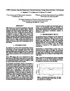
In section 2 we demonstrate the application of measured ToFs for localizing the transmit antenna position. Obviously, this procedure works very well if there is a LoS connection between the Tx and all of the Rx array elements. If we further assume that the transmit antenna is moved along some suitable chosen trajectory, the transmit antenna illuminates the propagation environment from different angles and a huge amount of information on the environment can be recorded from the back scattered part of the data. At the receiving array, also ToFs related to the paths which are influenced by the scattering objects can be estimated. The related time differences of arrival (TDoA) describe the paths direction of arrivals (DoAs). This information clearly indicates the geometry of the multipath propagation scenario which includes the coordinates of the reflecting objects. This is illustrated in Fig. 1 for single-bounce reflection. In section 3 we demonstrate the application of imaging algorithms, which are well known from radar imaging and ground penetrating radar [6]. It is very interesting to note that for the imaging procedure only a single Rx and Tx antenna pair (resp. a SISO link) is required since the spatial information on the environment is taken from the moving position of the Tx antenna. Multiple Rx antennas potentially increase resolution and accuracy. Throughout this paper we are using multiple Rx antennas to estimate the position of the moving terminal. So we suppose LoS between Tx and Rx. Section 4 describes a measurement example and Section 5 gives an outlook to UWB localization and imaging in distributed UWB sensor networks.
Scatterer
Transmit antenna
+ Time of flight 1
DoA 1
Time of flight 2
DoA 2
Receiver antenna array
Fig. 1 Channel sounding setup 2. Estimation of antenna positions The UWB channel sounding setup comprises a receiving antenna array which plays the role of the stationary (distributed) access point and a moving transmit antenna which emulates the UWB terminal (Fig. 2). The coordinates of the base station are assumed to be a priory known. The coordinates of the mobile antenna array are estimated by using the information stored in measured impulse responses. In case of narrowband systems, the assessment of the DoA information is based on phase difference estimation. Hence, the antenna distance is restricted to half lambda distance in order to avoid angular ambiguities because of phase periodicity. In case of UWB signaling, due to the excellent time resolution, estimation of the TDoA of the impinging waves is a better choice since this avoids ambiguities. Moreover, the antenna distance is no longer limited by some fraction of wavelength. It is even possible to increase the antenna distance and, thus, take an advantage in accuracy from the wider base line.
In our example, we have used a 2 element receive antenna array and a mobile station consisting of one transmit antenna (Fig. 2). The base station array defines the origin of the local coordinate system. The position of the moving transmit antenna Tx [x(t),y(t)] is estimated by using the ToFs of the electromagnetic wave from the transmitter to each of the antenna array element and the triangulation principle. y [x(t),y(t)]=?
2
D 2 2 x(t ) − + y (t ) = s2 (t ) 2
Tx
s1(t) s2(t) Rx1
Rx2
D/2 2
D 2 2 x(t ) + + y (t ) = s1 (t ) 2
D/2 [0,0] origin
x
Fig. 2 Estimation of antenna positions The ToF related to a certain element of the receive antenna array, determines the radius of a circle (around this antenna element) on which the target is situated. Those radiuses related to antenna Rx1 and Rx2 are referred to as s1(t) and s2(t) in Fig.2. The position of the transmit antenna is determined as an intersection of the two circles described by the following equations 2
D 2 2 x(t ) + + y (t ) = s1 (t ) 2 and 2
(1)
D 2 2 (2) x(t ) − + y (t ) = s 2 (t ) , 2 whereby s1(t) (s2(t) ) is a measured ToFt between the Tx and the Rx1 (Rx2) multiplied by the speed of light. The target Cartesian coordinates [x(t),y(t)] can be analytically computed from equations (1) and (2). Note that in case of two-element receive antenna array there is still a geometric ambiguity because the Cartesian coordinates are computed from the second polynomials. Therefore, there are two solutions that are related to the upper and lower half plane. An additional antenna element in the receive antenna array removes this ambiguity. In case of a 3D coordinate estimation, the minimum arrangement at the base station is a 4 element antenna array with the tetrahedron shape. This is similar to GPS localization. However, localization ambiguity is not an important point in case of GPS. Instead, in case of GPS we are faced with the problem of timing ambiguity because of different time bases between the synchronized
infrastructure and the stand-lone terminal. Here, we solved the problem of timing ambiguity by maintaining a wired connection between Tx and Rx. An operational localization system, which will lack the possibility of a direct wired connection for timing synchronization, can be installed by using of a further synchronized antenna which belongs to the (distributed) infrastructure. 3. Radar signal processing and UWB imaging Near range radar is usually applied to detect pipes, cables, other objects, anomalies or structures of the medium under test. Radar detects the backscattered pulses from the targets in background medium and shows the existence and position of these objects, but does not give the shape and profile. There are two different kinds of signal processing, which can be applied on measured data in order to obtain clear and more easily understandable radar images [9], [10], [11]. The first type is aimed to reveal CIR multipath components arising from object reflections and second one to processes data in such a way to give shape and profile to the objects. Let us assume for example a monostatic radar. In this case, one antenna is used for the transmission as well as for the reception of electromagnetic waves. When the antenna is moved past a single point-scatterer buried in homogenous transmission medium, the received echoes form a hyperbola (see Fig. 3). In this case, it is easy to determine the position of this simple scatterer if the propagation speed of electromagnetic waves in this medium is known. However, it is difficult or impossible to determine the position and the shape of more objects that are not simple point-scatterers directly from measured data. By means of sophisticated signal processing measured hyperbolas (2D measurement), or hyperboloids (3D measurement) can be focused into a single point and so form a spatial image of a medium under test and objects buried in it. The image focusing techniques are well functioning only if the following basic assumptions are met: • propagation speed of electromagnetic waves in the transmission medium is known, • there are only Rayleigh or specular reflections of electromagnetic waves from the objects. The last assumption is fulfilled only if the size of objects is much larger or much smaller than the wavelength of the stimulating signal. Otherwise, objects give rise to structural resonance or geometric induced dispersion of waveforms, what results in blurred focused images. There are two different algorithms for the image focusing: Kirchoff migration [9] and Stolt migration [10], [11]. The first one represents migration performed in time domain whereas the second one migrates data in frequency domain. The basic image formation process in Kirchoff migration can be explained using an object distribution function which describes distribution of objects in the propagation environment. Let us assume a scatterer situated in certain medium, a monostatic radar and measurement performed in 3D space. Further, suppose N different measurements at different antenna positions where n-th antenna position has co-ordinates [xn, yn, zn]. Measured signal at n-th antenna position will be abbreviated as Rn(t). An estimate of the object distribution function at point [x, y, z] is 1 N 2r (3) o( x, y, z ) = ∑ Rn n , N n=1 v
where
rn = ( x − x n ) 2 + ( y − y n ) 2 + ( z − z n ) 2 (4) is a distance from antenna position and v is the propagation speed. The quantity 2rn/v is a time necessary for the transmitted wave to propagate from the transmitting antenna to the point determined by co-ordinates [x, y, z] and backwards to the receiving antenna. The
measurement constellation describing above-mentioned facts for 2D case is depicted in Fig. 3. According equation (3) it is possible to say that estimation of object distribution function is a simple average over received waveform from each antenna position evaluated at the travel time (2rn/v) and related to each particular antenna position. It means that every antenna position measurement, which is one measured impulse response, has its own contribution to the result of object distribution function estimation. Y-direction
X-direction
AP = antenna position
AP1
AP2 r1
AP3
AP4 r4
r3
r2
AP5 r5
Point scatterer
2r3
2r2
2r4
2r1
2r5
Appearence of the point scatterer in the measured data (2D radargramm)
Fig. 3 Kirchoff migration – monostatic radar measurement arrangement In case of channel sounding it is also possible to compute an estimate of object distribution function. Although the measurement arrangement is different it is still possible to use the same philosophy and to migrate measured data in a way to deliver focused images of the propagation environment that brings geometrical information into the front. Kirchoff migration for the sounding measurement arrangement is illustrated in Fig. 4. X-direction
Rx – receive antenna Tx – transmit antenna
Y-direction
Rx
rrx Tx1
Tx2 r1t
Tx3
r3t
r2t
Tx4 r4t
Tx5 r5t
Point scatterer
rrx+r2t
rrx+r3t
rrx+r4t
rrx+r1t
rrx+r5t Appearence of the point scatterer in the measured data
Fig. 4 Kirchoff migration – channel sounding measurement arrangement
Here, one static antenna is used for the signal reception (Rx) and one moving antenna is used for the transmission. The varying positions of the moving antenna are referred to as Tx1, Tx2 and so on. From the presented sounding arrangement it is obvious that SISO measurements are sufficient for the focusing of measured images as far as one of both antennas is moved. The moving antenna creates by its movement a synthetic aperture and so provides information for the estimation of the object distribution function. All what is needed are measured CIRs containing sufficient amount of information about objects and known positions of antennas used for the sounding. 4. Measurement examples An experimental multi-channel (3 transmitters and 4 receivers) UWB sounding system covering the band from near DC to 4.5 GHz was used for the measurement examples described bellow. It uses integrated circuits (shift-register, binary divider and T&H) which have been designed at Ilmenau University of Technology in cooperation with MEODAT company [12]. It has superior jitter and drift behavior which is a result of the integrated implementation in very fast SiGe:C-Technology (fabricated at IHP Frankfurt/Oder). It features 60dB dynamic range that is achieved by only a simple 2-term calibration of the system. For more details on the system description, the reader is pointed to [12], [13], [14], [15]. Within the imaging experiments it was observed that one crucial point for the imaging is the precision of the antenna position estimation. The precision dependents on the arrangement of antenna elements within the array, measurement system performance (its jitter and noise) and on the availability of the antenna radiation characteristics for the data calibration. The following example demonstrates the precision of the 2D position estimation of a moving antenna. Here, a static antenna array consisting of 3 Vivaldi antennas was used for the signal reception. The receive antennas formed in the horizontal plane a triangular antenna array (equal-sided with the antenna distance of 0.5m). The transmit biconical antenna was mounted on a 2D positioning unit allowing the precise positioning of objects in an area of 2 meters by 4 meters with 0.75 mm precision in two directions. Continuous sweeps could be realized with a maximum speed of about 130 mm/s in x-direction and 170 mm/s in the y-direction, respectively. The transmit antenna was moved along a predefined track with the maximum velocity allowed by this positioning unit. Data was measured by the UWB system with measurement rate of about 11 CIR per second and the whole measurement lasted only for about 60 seconds. Fig. 5 shows results of the position estimation. There are illustrated results of the position estimation using 3 different algorithms and the track along which the transmit antenna was moved in reality. It is a connection of points with following coordinates [0;0.17], [2;0.17], [2;2.05] and [0;2.05]. All 3 used estimation algorithms were based on triangulation principles described above. Firstly, time of flight between the transmit and receive antenna was estimated. Then, the antenna position was computed analytically solving equations (1) and (2). The first algorithm estimated time of flight in a very simple way –looking for the position of a maximum in a match filtered (MF) impulse response. The filter was matched to the mean (averaged over azimuth) impulse response of the antenna. The antenna response was gained by the calibration measurement. Second algorithm improved the estimation performing an interpolation in the maximum position search. The third algorithm used the interpolation as the second one but used an adaptive MF. This MF was adapted to the real (not mean as before) antenna impulse response corresponding to the actual azimuth. Antenna impulse responses were estimated from the calibration measurement. Thus, it means that the first two algorithms did not encountered antenna radiation characteristics for the position estimation. The influence of neglecting antenna characteristics is clearly visible in the detailed view in Fig. 5. Here, the first (the most simple) algorithm estimated positions of the moving antenna
that do not follow the real track and moreover estimated positions are scattered (time of flight precision was only in an order of 100ps). Estimated positions of the second algorithm are not scattered, but they are still far away from the real track (neglected antenna characteristics). The third adaptive algorithm, taking into account antenna characteristics, estimated positions with a high precision. The standard deviation of the range estimation was in an order of 3mm and the standard deviation of the azimuth (2D estimates) was in an order of 0.75 degree.
No interpolation, no knowledge of ant. characteristics
Interpolated with knowledge of ant. characteristics
Interpolated without knowledge of ant. characteristics
Fig. 6 Detailed view
Fig. 5 Estimated positions of moving transmit antenna
The precise estimation of antenna positions allows implementation of the focusing algorithm, as described above, directly on channel sounder measured data. This kind of UWB imaging is shown by the following measurement experiment. Here, the same measurement arrangement was used as in the previous measurement example. The measurement scenario is depicted in Fig. 7. There is illustrated the track along witch the transmit antenna was moved and the triangular receive antenna array. Moving transmitt antenna
Track of the Tx antenna movement
Triangular receive antenna array PC station
Fig. 7 Measurement scenario Measured data of one receive antenna (1000 impulse responses) are illustrated in Fig. 8. Here, the direct wave is clearly visible. This direct wave altogether with the direct waves measured by other 2 receive antennas were used for the localization of the moving transmit antenna. Multipath components can be extracted from the measured data by signal preprocessing (see Fig. 9). They provide information about the propagation environment that is necessary for the UWB imaging.
Direct wave
Multipath components Fig. 9 Preprocessed data
Fig. 8 Measured data
Firstly, antenna positions were estimated from measured data. Than, data were preprocessed (system calibration, filtering) and finally focused by Kirchoff migration. The result of the data focusing is illustrated in Fig. 10. The walls of the measurement lab can be clearly identified from the presented UWB image.
Receive antenna array
*
* * Walls
Fig. 10 UWB image of the propagation environment 5 Outlook and Conclusions We have demonstrated the application of radar imaging methods to generate an object distribution map of the propagation environment from real-time UWB sounding data. The procedure relies only on SISO measurements and takes the necessary spatial information from the motion of only one antenna. The required precise position of the moving antenna is estimated by using a distributed Rx antenna array and ToF measurement. We have presented a
very first measurement example. The proposed measurement procedure offers interesting farreaching perspectives summarized as: •
• •
•
•
•
•
High-resolution, 3D-characterization of the multipath propagation. UWB imaging of the propagation environment helps to better understand the propagation phenomena and to deduce geometric channel models. Even more detailed information can be deduced by full polarimetric measurement and by the analysis of the dispersive nature of backscattered signals. A specific advantage of UWB imaging is the ability to look through or inside of structures or materials. Double directional MIMO channel investigation. The real-time MIMO capability of the sounder [8] offers the possibility for double directional UWB sounding in a timevarying propagation environment. Localization of static and moving objects. The demonstrated example was restricted to the imaging of stationary parts of the environment. The procedure can be extended to separate between stationary and moving objects. This requires an additional transmit antenna which is kept stationary throughout the measurement procedure. The information resulting from this antenna helps to detect the moving part of the environment. High-resolution, 3D active localization. The example shows the potential localization performance of UWB terminals. Since the terminal actively transmits (or receives) a UWB signal and since, in general, there is a cooperative interaction of the terminal and the infrastructure, we call this “active localization”. The localization performance can be maximized by an optimum arrangement of the infrastructure antennas in order to minimize the geometric dilution of precision. This optimization has to consider also site specific effects such as multipath and LoS shadowing. Robust localization procedures are required to mitigate missing LoS. The proposed SIMO sounder measurements can be used to deduce geometrically correct channel models for localizer performance evaluation. Joint active and passive localization. The example demonstrates that a UWB terminal can gain considerable information about the geometric and electromagnetic structure of the propagation environment if it is only moving. So an active (e.g. infrastructure based) localization system can take considerable advantage with respect to accuracy, ambiguity, integrity, and robustness if the available information on the propagation environment is additionally or jointly used. One simple example is the detection of unexpected (perhaps time varying) obstacles by a moving robot. Cooperative, distributed sensor networks. Distributed ad-hoc sensor networks are discussed as one promising application scenario of UWB technology. There seems to be a strong interaction between the localization ability of UWB terminals and the network organization. Location aware routing has already been intensively discussed in the mobile network community. However, ad-hoc organized and adaptively optimized localization sensor networks still seem to be an open field of research. UWB frequency range and hardware design progress. We have demonstrated baseband UWB measurements with a bandwidth of some hundreds of MHz to 4.5 GHz. The lower frequencies are important if wall material penetration is required. If FCC conform bandwidth is more important (e.g. from about 3 to 12 GHz), heterodyne up/down conversion is required.
References [1]
R.S. Thomä, M. Landmann, A. Richter, U., Trautwein, “Multidimensional High-Resolution Channel Sounding,” in Smart Antennas in Europe – State-of-the-Art, EURASIP Book Series, Hindawi Publishing Corporation, to appear 2005
[2]
D. Cassioli, M. Z. Win, and A. F. Molisch, “The ultra-wide bandwidth indoor channel: from statistical model to simulations,” IEEE J. Select. Areas Commun., Vol. 20, No. 5, pp. 1247– 1257, Aug. 2002.
[3]
J. Kunisch and J. Pamp, “An ultra-wideband space-variant multipath indoor radio channel model,” in Proc. IEEE Conf. on Ultra Wideband Systems and Technologies 2003, pp. 290–294, Reston, VA, USA, Nov. 2003.
[4]
R.J.M. Cramer, M.Z. Win, R.A. Scholtz, “Evaluation of the Multipath Characteristics of the Impulse Radio Channels,” IEEE International Antenna and Propagation Symposium, pp. 626630, June 1998.
[5]
K. Haneda, and J. Takada, “An application of SAGE algorithm for UWB propagation channel estimation,” in Proc. IEEE Conf. on Ultra Wideband Systems and Technologies 2003 (UWBST2003), pp. 483–487, Reston, VA, USA, Nov 2003.
[6]
K. Haneda, J. Takada, and T. Kobayashi, “Experimental evaluation of a SAGE algorithm for UWB channel sounding in an anechoic chamber,” in Proc. 2004 International Workshop on Ultra Wideband Systems Joint with Conference on Ultra Wideband Systems and Technologies (UWBST & IWUWBS2004), pp. 60– 70, Kyoto, Japan, May 2004.
[7]
K. Haneda, J. Takada, and T. Kobayashi, “Double directional line-of-sight channel characterization in a home environment with ultra wideband signal,” Int. Conf. on Wireless Personal Multimedia Communications 2004 (WPMC ’04), Padova, Italy, Sept. 2004.
[8]
R. Zetik, R. Thomä, J. Sachs, “Ultra-wideband real-time channel sounder design and application,” URSI International symposium on electromagnetic theory, Pisa, Italy, May 2004.
[9]
D.J.Daniels, “Surface-penetrating radar,” IEE Radar, Sonar, Navigation and Avionics Series 6, 1996.
[10] A.J.Berkhout, “Seismic Migration-Imaging of Acoustic Energy by Wave Field Extrapolation, A Practical Aspects,” Amsterdam-Oxford-New York-Tokyo, 1984. [11] A.J.Berkhout, ”Seismic Migration-Imaging of Acoustic Energy by Wave Field Extrapolation, A Theoretical Aspects,” Amsterdam-Oxford-New York-Tokyo, 1985. [12] www.meodat.com [13] J. Sachs, P. Peyerl, M. Roßberg, “A New UWB-Principle for Sensor-Array Application,” Instrumentation and Measurement Technology Conference IMTC/99, Venice, Italy, May 1999. [14] M. Roßberg, J. Sachs, P. Rauschenbach, P.Peyerl, K. Pressel, W. Winkler, D. Knoll, “11 GHz SiGe Circuits for Ultra Wideband Radar,” IEEE Bipolar/BiCMOS Circuits and Technology Meeting, Minneapolis, USA September 25-26, 2000. [15] J. Sachs, M. Roßberg, P. Rauschenbach, P. Peyerl, J. Friedrich, “Integrated UWB Radar Circuit for Base Band Applications from DC to 5 GHz,” GRS 2000 , Berlin, Germany, October 2000.