Most of the existing forensic methods aimed at detecting duplicated regions in ... 1. INTRODUCTION. Existing image editing software provides powerful tools that.
17th European Signal Processing Conference (EUSIPCO 2009)
Glasgow, Scotland, August 24-28, 2009
PASSIVE FORENSIC METHOD FOR DETECTING DUPLICATED REGIONS AFFECTED BY REFLECTION, ROTATION AND SCALING Sergio Bravo-Solorio and Asoke K. Nandi Department of Electrical Eng. & Electronics. The University of Liverpool Brownlow Hill, Liverpool, L69 3GZ, UK. email: {sbravo, aknandi}@liv.ac.uk
ABSTRACT
Table 1: General classification of techniques intended for integrity verification of images. Active Passive Non-invasive Trustworthy dig- Passive image ital cameras [4] forensics [3, 10] Invasive Fragile water- marking [2]
Most of the existing forensic methods aimed at detecting duplicated regions in images are sensitive to geometrical changes in the replicated areas. Consequently, a simple reflection/rotation of the copied region could be used to not only suit the scene of the image, but also hinder its proper detection. In this paper, we propose a novel forensic method to detect duplicated regions, even when the copied portion have experienced reflection, rotation or scaling. To achieve this, overlapping blocks of pixels are re-sampled into log-polar coordinates, and then summed along the angle axis, to obtain a one-dimensional descriptor invariant to reflection and rotation. Moreover, scaling in rectangular coordinates results in a simple translation of the descriptor. This approach allows us to perform an efficient search of similar blocks, by means of the correlation coefficient of its Fourier magnitudes. Results are presented to demonstrate the effectiveness of the proposed method.
A commonly considered manipulation consists in concealing undesired regions of the image by covering them with segments copied from another part of the same image [3, 10]. Forensic methods aimed at detecting duplicated regions must also consider other manipulations which could seriously affect their performance. In this paper, we explore the case where the copied region has undergone geometrical transformations such as reflection, rotation or scaling. This sort of distortions can be employed not only to suit the scene in the image being doctored, but also to hinder its detection with current forensic methods. We propose a novel forensic technique to detect duplicated regions in images by means of 1-D reflection/rotation-invariant descriptors derived from log-polar maps. Results show that the method can effectively detect duplicated regions affected by geometrical transformations. The paper is organised as follows. Related research is described in Section 2. Section 3 is focused on the proposed 1-D descriptors and its properties. In Section 4, the proposed method is presented. Some results are reported in Section 5, and the paper is concluded in Section 6.
1. INTRODUCTION Existing image editing software provides powerful tools that can be used to doctor images which cannot be easily identified, even by trained observers. A general classification of the techniques proposed to address this concern is shown in Table 1. The concept of Trustworthy Digital Camera, introduced by Friedman [4], can be considered as an active technique, whereby a digital signature is computed with the camera at the time of capturing, and then appended to the image as metadata. This method is non-invasive in the sense that the image is not distorted at all by this process. Fragile watermarking [2] is another active technique, whereby certain information is imperceptibly embedded in images for future authentication. Since certain distortion is unavoidable during the embedding process, this technique can be regarded as invasive. Active techniques are limited to controlled environments, such as surveillance cameras, where the capturing devices are equipped with a proper system to either compute the digital signature or embed the watermark. Passive image forensics [3, 10], in contrast, are designed to determine whether an image has been manipulated without relying on any information generated a priori. Sometimes, these techniques work on the assumption that forgeries may alter the underlying statistics of images, even though no traces can be identified under visual inspection [3]. In practise, because of the difficulty of the problem, forensic evidence will often rely on various methods, rather than one specific algorithm.
2. PRIOR ART There have been various recent forensic methods designed to detect duplicated regions. Fridrich et al. [3] presented an approach where the Discrete Cosine Transform (DCT) is computed on overlapping blocks of pixels. Then the coefficients are JPEG-like quantised and lexicographically sorted. Hence, matching pairs of blocks can be readily identified, as they are expected to have equal coefficients. Popescu and Farid [10] presented a similar approach where a dimensionreduced representation is computed for each block by means of Principal Component Analysis (PCA). The computational cost is significantly reduced with this technique, which is also robust to minor variations induced by additive noise or lossy compression. Langille and Gong [5] improved the efficiency of the previous methods by grouping the blocks with a modified k-dimensional tree. Then the detected duplicated regions are refined by employing a set of colour-based morphology operations. Mahdian and Saic [8] presented a
Sergio Bravo-Solorio is supported by the National Council of Science and Technology (CONACyT) of Mexico.
© EURASIP, 2009
824
method based on blur moment invariants, where duplicated regions can be identified even after blur degradation, additive noise, or changes in contrast. In the method presented by Myna et al. [9], the Discrete Wavelet Transform (DWT) is firstly computed over the input image. Overlapping blocks of wavelet coefficients in the coarser sub-band of the lower resolution level are mapped to log-polar coordinates. The resulting blocks are lexicographically sorted and analysed to identify similar pairs. The formed pairs are iteratively compared in subsequent resolution levels, and discarded when the similarity criterion is not fulfilled. Results show that the algorithm is capable of detecting duplicated regions even after undergoing certain rotation. However, the lack of detail in the coarser sub-band in the lower resolution level can significantly increase the correlation between blocks, rising thus the number of blocks that must be analysed in subsequent resolution levels. This can significantly affect the computational cost, since the blocks size must be doubled for every resolution level.
A reflected, rotated and scaled version of Bi can be expressed in log-polar coordinates as B′i (ρ , θ ) = Bi (ρ + log µ , ϕ − θ ). Computing a descriptor for this block, we get ~vi ′ (ρ ) = ∑ B′i (ρ , θ ) ,
(5)
θ
= ∑ Bi (ρ + log µ , θˆ ) ,
(6)
θˆ
where θˆ = (ϕ − θ ). Since cosines and sines are periodic functions, and we consider a whole period, and the change in θˆ is linear, it follows that we can re-write (6) as, ~vi ′ (ρ ) = ∑ B(ρ + log µ , θ ) .
(7)
θ
Hence, both descriptors are invariant to both reflection and rotation, i.e. ~vi (ρ ) =~vi ′ (ρ ), when B′i is a mirrored and/or rotated version of Bi . Furthermore, ~vi (ρ ) = ~vi ′ (ρ − log µ ), when B′i is a scaled version of Bi by a factor µ . In discrete signals though, we must consider loss due to interpolation and round-off errors. Thus, because of the well-known translation properties of the Fourier transform [1], the Fourier magnitude of both descriptors are expected to be very closely correlated to each other, i.e.,
3. SOLVING REFLECTION, ROTATION AND SCALING To cope with reflection, rotation and scaling, blocks of pixels are mapped to 1-D descriptors resulting of summing the pixels in their log-polar representation along the angle axis. This approach was inspired by the watermarking technique in [6], which was designed to overcome the synchronisation problems caused by rotation, scaling and translation. In that case, 1-D descriptors were computed by summing a log-polar map along the log-radius axis.
~ViT ~Vi ′ c(~Vi ,~Vi ′ ) = q ≈1 , (~ViT ~Vi )(~Vi ′T ~Vi ′ )
3.1 Computing the 1-D descriptors
(8)
where c is the correlation coefficient, ~Vi and ~Vi ′ are the Fourier magnitudes of ~vi and ~vi ′ , respectively.
R2 ,
Consider the point (x, y) ∈ which can be written using (natural) log-polar coordinates,
3.2 Advantages of 1-D descriptors x = e ρ cos θ ,
Compared to complete log-polar maps, the main benefits of 1-D descriptors are, 1. Reflection - The detection of mirrored duplicated blocks is simplified by 1-D descriptors. Reflecting an image results in a flip of its log-polar map. 2. Memory - Since every single block will be compared with several blocks, it is a good idea to form an array with the descriptor corresponding to each block, before the search stage. Thus, instead of storing a complete mρ × nθ logpolar map for every block, we only need to store a vector of length mρ . 3. Computational cost - The calculation of the proposed descriptors involves the same computational cost as the complete log-polar map. Nonetheless, the computational cost of whole algorithm significantly drops, as we only need to compute the Fast Fourier Transform (FFT) of vectors, whose complexity is known to be O(mρ log mρ ), instead of computing the FFT of log-polar maps, whose complexity would be O((mρ nθ ) log(mρ nθ )).
(1)
ρ
y = e sin θ , where ρ ∈ R and 0 ≤ θ < 2π . Let (x ′ , y ′ ) denote the coordinates of a reflected, rotated and scaled point, i.e., x ′ = µ (x cos ϕ + y sin ϕ ) ,
(2)
y = µ (x sin ϕ − y cos ϕ ) , ′
where ϕ and µ are the parameters of rotation and scaling, respectively. Rewriting (2) in log-polar form we get, x ′ = e (ρ +log µ ) cos(ϕ − θ ) , ′
y =e
(ρ +log µ )
(3)
sin(ϕ − θ ) .
Observe that scaling in rectangular coordinates results in a simple translation of the log-polar map. Consider a block of pixels1 Bi (x, y) and its log-polar representation Bi (ρ , θ ). We can define a 1-D descriptor ~vi as ~vi (ρ ) = ∑ Bi (ρ , θ ) .
4. PROPOSED ALGORITHM Consider a colour image X, of size mX × nX , which is tiled as blocks of pixels selected by sliding, pixel by pixel, a window of size q × q, from the top-left corner to the bottom-right corner, in a raster-scan order. Let Ai denote the i-th block of pixels -for i = 1, . . . , (mX − q + 1)(nX − q + 1). The proposed
(4)
θ
1 The index i is merely included for the sake of consistency in the notation employed in the subsequent section.
825
method is comprised of three general stages, namely block sorting, search, and refinement. The algorithm is detailed below: 1: The blocks are sorted to reduce the computational cost of the search stage. The centre of each block Ai will be the centre of a disk of diameter q. Let f1i , f2i , and f3i be the average of the red, blue and green colour components2 , respectively, of the pixels within the disc. Additionally, the luminance of the pixels within the disc is computed as Y = 0.2126 r + 0.7152g + 0.0722b, where r, g, and b are components of red, green and blue, respectively. Then the entropy is calculated as,
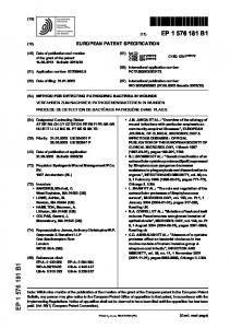
0.6 Lena mean Lena std dev Peppers mean Peppers std dev F-16 mean F-16 std dev Baboon mean Baboon std dev
Average Difference in Red Channel
0.5
0.4
0.3
0.2
0.1
0
f4i = − ∑ pk log2 pk ,
-0.1 0
10
20
30
k
3:
60
70
80
90
(a)
where pk is the probability of each luminance value in the disc. To reduce the occurrence of false matches, blocks where the computed entropy is lower than a predefined threshold emin are discarded. Then a list L is formed with the tuple of features ( f1i , f2i , f3i , f4i ) corresponding to the remaining blocks. Let us define Lˆ as the result of lexicographically sorting the list L. Additionally, let Bi be the i-th block of pixels ˆ and the tuple (xi , yi ) be the coordinates (the upperin L, left corner) of Bi in the image X. A descriptor ~vi is computed for every Bi by (4), and its Fourier magnitude ~Vi is calculated. Then, the correlation coefficient ci j = c(~Vi ,~V j ) is computed, for every j > i that satisfies the three following conditions: a) di j > τd , b) ( fki − τa ) ≤ fk j ≤ ( fki + τa ), for k = 1, 2, 3, c) ( f4i − τe ) ≤ f4 j ≤ ( f4i + τe ), p where di j = (xi − x j )2 + (yi − y j )2 , and τd , τa , τe are predefined thresholds. Note that, since Lˆ is sorted, the comparisons for ~Vi can stop once a descriptor ~Vu is reached, such that f1u > ( f1i + τa ). Let us assume that cir was the higher correlation coefficient computed for ~Vi . If cir > τsim , a tuple ( x δir , y δir , xi , yi , xr , yr ) is appended to a list Q, where x δir = |xi − xr | and y δir = |yi − yr | are the offsets of the two pairs of coordinates. The list Q is sorted in accordance with the offsets to form ˆ Then, Qˆ is scanned to identify clusters a new list Q. with similar -i.e. not necessarily equal- offsets. Finally, a bitmap is encoded with the clusters that contain more blocks than a predefined threshold τnum .
0.3 Lena mean Lena std dev Peppers mean Peppers std dev F-16 mean F-16 std dev Baboon mean Baboon std dev
0.2
Average Difference in Entropy
2:
40 50 Rotation Degree
0.1
0
-0.1
-0.2
-0.3
-0.4 0
10
20
30
40 50 Rotation Degree
60
70
80
90
(b)
Figure 1: Distortion caused by rotation in the average of the red channel and the entropy. to detect small duplicated regions. Additionally, we set the threshold τd to 32, to avoid matches of blocks in a very close proximity to each other. To determine the thresholds τa and τe , required in the search stage, we formulated an experiment with the standard images: Lena, Peppers, F-16 and Baboon. As in the proposed algorithm, the images were tiled in blocks by sliding a window of size 16 × 16, from the upper-left corner to the lower-right corner in raster scan order. Each block was translated3 a random amount within the range [−0.5, 0.5], in a random direction, and subsequently rotated 5◦ . We applied a mask to extract a disk of diameter 16 from both the original and the rotated blocks, and computed the difference between the average of the three colour channels and the entropy of the luminance channel (see stage 1 in the algorithm in Section 4). The experiment was repeated for different rotations, namely 15◦ , 30◦ , 45◦ , 60◦ , 75◦ , 85◦ and 90◦ . We gathered these results, calculated their mean and their standard deviation. For the sake of brevity, we only present the graphs obtained for the red channel and the entropy in Figs. 1(a) and 1(b), respectively. We found that the distortion induced in the average value of the three channels, in 99.8% of blocks, was in the range [−1, 1]. Besides, the distortion induced in the entropy, in 96.6% of the blocks, was in the range [−0.3, 0.3].
5. RESULTS Before proceeding with the experiments, we will briefly describe the set-up of the system. 5.1 Parameters set-up In our experiments, the blocks-size was set to 16 × 16, and the length of the 1-D descriptor computed for each block was set to 8. We have empirically found that such a configuration allows us to maintain a reasonable balance between the appearance of false matches and the capacity of the system 2 Luo et al. [7] used the average of the colour channels and showed that such features are not significantly modified by JPEG compression or Gaussian blurring.
3 The translation was necessary to reproduce a typical situation when the centre of rotation is not the exact centre of the block being analysed.
826
A similar experiment was formulated for different scaling factors, from 0.8 to 1.15 with increments of 0.05. We found that the distortion experienced by the average of the three colour channels is in the range [−1, 1] in 18% of the blocks. Moreover, in 94% of the blocks, the distortion induced in the entropy was in the range [−0.3, 0.3]. We decided to set the thresholds τa and τe to 1.0 and 0.3, respectively, to maintain a low computational cost, at the expense of reducing the capacity of detecting changes in scaling. To define the threshold τsim , we performed a similar experiment, but, instead of computing the features, we calculated the correlation coefficient between the Fourier magnitude of the descriptors extracted from the original and the distorted blocks. The threshold τsim was set to 0.99985, as the correlation coefficient calculated from 98.2% of the blocks fell above this value.
Table 2: Results obtained from the example forgeries. Image Accuracy (α ) False positives (ε ) Beach 1.0 0.21 0.86 0.0 Leaves 0.63 0.21 Clif 0.49 0.04 Cow
3(c) depicts an image with large obscure regions, which are also expected to pose a challenge to the proposed method. A randomly chosen block of size 52 × 52 was subjected to a geometrical distortion before being superimposed in another random location within the same image. From each test image, we formed four forgeries, each one involving a different distortion, namely, reflection, random rotation, random scaling, or no distortion at all (for comparison purposes). Results are summarised in Table 3. In all the cases, the duplicated regions were successfully detected in the Building image, in Fig. 3(a), and the symmetrical structures did not increased the false positives. The copied region was properly detected in the House image, in Fig. 3(b), except for the scaling test. Unexpectedly though, some regions by the building in the rear part were mistakenly deemed duplicates. The duplicated areas were successfully detected in the River image, in Fig. 3(c), in all the cases. Nonetheless, as expected, some regions in the bottom-left part were mistakenly deemed duplicates.
5.2 Example forgeries To show the capability of our method to detect duplicated regions affected reflection, rotation or scaling, we used the test images, shown in Figs. 2(a)-2(d), to create four different forgeries. • A segment of the image in Fig. 2(a) was copied, without applying any further distortion, to conceal the woman near the centre, and get the forgery in Fig. 2(e). • An horizontally flipped region of the Leaves image, in Fig. 2(b), was used to conceal the tree by the upper-right corner. The forgery is shown in Fig. 2(f). • The person on the cliff, in Fig. 2(c), was covered by a 30◦ rotated portion of the rocks in the opposite side, to get the forgery in Fig. 2(g). • A copy of the cow, in Fig. 2(d), was scaled 95% of its original size and superimposed in the left part to cover the other animals in the scene to get Fig. 2(h). Let E be the bitmap map encoded by our system, and G be the ground truth, which shows the exact duplicated regions. The accuracy α of our results, and the false positives ε (regions mistakenly detected as duplicates), will be given by,
α=
E
T
G
G
, and, ε =
E
S
G
G
Table 3: Results obtained after applying different distortions to the duplicated region. Images Building House River Distortion Measure Accuracy (α ) 0.99 0.99 0.85 Move F. positive (ε ) 0.20 0.08 2.15 Accuracy (α ) 0.53 0.92 0.78 Reflection F. positive (ε ) 0.01 0.04 2.10 Accuracy (α ) 0.29 0.44 0.51 Rotation F. positive (ε ) 0.01 0.53 1.94 Accuracy (α ) 0.22 0.0 0.95 Scaling F. positive (ε ) 0.20 0.50 2.57
−1 ,
where the ideal detection would give α = 1 and ε = 0. The results can be visually inspected in Figs. 2(i)-2(l), where the retrieved bitmaps are compared with their respective ground truth. The darker grey areas depict the duplicated regions that were successfully detected, the black areas illustrate undetected duplicated regions, and the white areas show the parts that were mistakenly deemed duplicates. The measures of accuracy and the false positive are summarised in Table 2. The system managed to detect the four forgeries successfully. As expected though, the best results were obtained from the Beach and the Leaves forgeries, as the copied blocks suffered no loss due to interpolation and round-off errors.
6. CONCLUSIVE REMARKS We have presented a forensic method to detect duplicated regions, even when the copied portion has experienced geometrical distortions such as reflection, rotation or scaling. The log-polar representation of a block of pixel is summed along its angle axis, to get a 1-D descriptor invariant to reflection and rotation. Reported results show the effectiveness of the proposed approach. Further work involves improving the last refinement stage to increase the accuracy and decrease the false positives. Moreover, we plan to exhaustively test the method in different images with several distortions, including combinations of the previous geometrical transformations, JPEG compression, additive noise and Gaussian blurring. Results are expected to be reported soon in a future publication.
5.3 Further tests We selected three images with particular characteristics. Figure 3(a) depicts a building with many symmetrical structures, which are expected to increase the false positives. An image with large textured regions is shown in Fig. 3(b). And Fig.
827
(a)
(b)
(c)
(d)
(e)
(f)
(g)
(h)
(i)
(j)
(k)
(l)
Figure 2: Example forgeries. Original test images: (a) Beach. (b) Leaves. (c) Cliff. (d) Cow. Doctored images where the copied region has undergone: (e) no further distortion, (f) horizontal reflection, (g) 30◦ rotation, (h) 95% scaling. (i)-(l) Comparison between the obtained results and the ground truth.
(a)
(b)
(c)
Figure 3: Test images. (a) Building. (b) House. (c) River. REFERENCES
cessing, 10(5):767 – 782, 2001. [7] W. Luo, J. Huang, and G. Qui. Robust detection of region-duplication forgery in digital images. In Proc. of the IEEE International Conference on Pattern Recognition, volume 4, pages 746–749, 2006. [8] B. Mahdian and S. Saic. Detection of copy-move forgery using a method based on blur moment invariants. Forensic Science International, 171(2-3):180– 189, 2007. [9] A. N. Myna, M. G. Venkateshmurthy, and C. G. Patil. Detection of region duplication forgery in digital images using wavelets and log-polar mapping. In Proc. of the International Conference on Computational Intelligence and Multimedia Applications, pages 371–377, Washington, DC, USA, 2007. [10] A. C. Popescu and H. Farid. Exposing digital forgeries by detecting duplicated image regions. Technical report, Department of Computer Science, Dartmouth College, 2004.
[1] R. N. Bracewell. The Fourier transform and its application. McGraw-Hill, 1986. [2] I. J. Cox, M. L. Miller, J. A. Bloom, J. Fridrich, and T. Kalker. Digital Watermarking and Steganography. Morgan Kauffman, 2nd edition, 2008. [3] J. Fridrich, D. Soukal, and J. Luk´asˇ. Detection of copymove forgery in digital images. In Proc. of Digital Forensic Research Workshop, August 2003. [4] G. Friedman. The trustworthy digital camera: restoring credibility to the photographic image. IEEE Transactions on Consumer Electronics, 39(4):905 – 10, 1993. [5] A. Langille and M. Gong. An efficient match-based duplication detection algorithm. In Proc. of the 3rd Canadian Conference on Computer and Robot Vision, page 64, 2006. [6] C.-Y. Lin, M. Wu, J. Bloom, I. Cox, M. Miller, and Y. Lui. Rotation, scale, and translation resilient watermaking for images. IEEE Transactions on Image Pro-
828