Patch clamp techniques for single channel and whole-cell recording. DAVID OGDEN and PETER STANFIELD. 1. Introduction. The patch clamp technique was ...
53 Chapter 4
Patch clamp techniques for single channel and whole-cell recording DAVID OGDEN and PETER STANFIELD
1. Introduction The patch clamp technique was first used by Neher and Sakmann (1976) to resolve currents through single acetylcholine-activated channels in cell-attached patches of membrane of frog skeletal muscle. The method they used (described by Neher, Sakmann & Steinbach, 1978) and subsequent refinements (Hamill, Marty, Neher, Sakmann & Sigworth, 1981) have led to techniques for high resolution recording of current in excised membrane patches in addition to those that remain cell-attached. Single channel recording yields information about unitary conductance and kinetic behaviour of ionic channels already partly investigated by classical voltage clamping and by noise analysis; it is also leading to the discovery of new classes of ion channel. Together with the method of whole-cell recording, which permits the application of voltage clamping to cells that are too small for microelectrode methods, patch clamp techniques also permit investigations of the physiological role of ionic channels in cells otherwise inaccessible to voltage clamp and to cells that are not electrically excitable.
2. Method for patch clamp recording The principle of the method is to isolate a patch of membrane electrically from the external solution and to record current flowing into the patch. This is achieved by pressing a fire-polished glass pipette, which has been filled with a suitable electrolyte solution, against the surface of a cell and applying light suction. Providing both glass pipette and cell membrane are clean, a seal whose electrical resistance is more than 10 GΩ is formed. Under such conditions, the glass pipette and the cell membrane will be less than 1 nm apart. A high seal resistance is needed for two reasons. First, the higher the seal DAVID OGDEN, National Institute for Medical Research, Mill Hill, London NW7 1AA, UK PETER STANFIELD, Department of Physiology, University of Leicester, Leicester LE1 9HN, UK
54
D. OGDEN AND P. STANFIELD
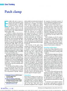
resistance, the more complete is the electrical isolation of the membrane patch. Secondly, a high seal resistance reduces the current noise of the recording, permitting good time resolution of single channel currents, currents whose amplitude is in the order of 1 pA. Fig. 1 illustrates an equivalent circuit for the recording set-up. The fraction of the current flowing through the patch that will be collected by the recording pipette is Rseal/(Rseal + Rpipette) where Rseal is the seal and Rpipette the pipette resistance. As Fig. 1 also illustrates, it is necessary that the patch from which recordings are made be small in area, compared with the area of membrane of the cell as a whole. In terms of Fig. 1, it is necessary that Rcell«Rpatch if single channel currents are not to alter the membrane potential of the cell significantly.
Fig. 1. The relation of pipette to cell and the equivalent electrical circuit during patch clamp recording. The opening of an ion channel is represented as the closing of the switch in Fig. 1b. The pipette resistance and seal resistance are in series between the amplifier and earth (the external solution) and the patch and cell resistances are in parallel with the seal resistance in this path.
Patch clamp techniques
55
The background noise level is also minimized by a high seal resistance. The variance of the current noise (in A2) through a resistor (R, Ω) is related to the Johnson voltage noise due to the resistance, being given by: si2 = 4kTfc/R where k is Boltzmann’s constant, T is temperature (°Kelvin), and fc is the bandwidth (Hz) i.e. the low pass filter setting. Thus, for a 10 GΩ resistor at 20°C, the standard deviation of the current noise at 1 kHz will be 0.04 pA, but for a resistor of 100 MΩ it will be 0.4 pA. In the recording situation used in patch clamp (Fig. 1), resistor current noise will depend on all the resistive paths to ground from the amplifier input, decreasing as resistance increases. Since the patch resistance is high (approximately 100 GΩ or more), the low seal resistance predominates and will result in noise that will prevent good resolution of currents smaller than 4 or 5 pA. Such was the situation in the earliest patch clamp experiments, where the seal resistance was less than 100 MΩ. In spite of this difficulty, information was obtained about acetylcholineactivated channels (Neher & Sakmann, 1976), about the blocking effects of local anaesthetics on such channels (Neher & Steinbach, 1978), and about glutamateactivated channels of insect muscle (Patlak, Gration & Usherwood, 1979; CullCandy, Miledi & Parker, 1981). The achievement of ‘gigaseals’ (>1 GΩ, Neher, 1981; Hamill et al. 1981), however, radically improved the quality of recording and made it possible to study channels of lower unitary conductance. Such seals are generally achieved in an all-or-nothing fashion and result in a dramatic improvement in signal-to-noise ratio. The conditions that appear to be required for the formation of a gigaseal are the following. First, the surface membrane of the cell used must be clean and free of extracellular matrix and connective tissue. Cells in tissue culture are often preferred; adult cells generally must be cleaned enzymatically or mechanically. Secondly, solutions should be free of dust and of macromolecules such as the components of serum in tissue culture media. Solutions are filtered using 0.2 µm filters (of the detergent-free type). Cell cultures are washed several times to remove serum. Thirdly, the pipette tip is clean, often by fire-polishing. Fourthly, during the period just prior to seal formation, a small positive pressure is applied to the pipette to generate an outflow of solution from the pipette tip and so keep it free of debris. Loose-patch clamp In certain situations, however, a low seal resistance can be an advantage. Such a method is the so-called ‘loose-patch’ clamp (Almers, Stanfield & Stühmer, 1983), developed to allow measurement of the distribution of ionic channels over cell membranes and, making use of the low resistance seal and the resulting gap that will exist between membrane and recording pipette, to permit investigation of the lateral mobility of ionic channels. Here large diameter (approximately 10 µm) pipettes are used to collect current from many ionic channels at the same time. Currents that are
56
D. OGDEN AND P. STANFIELD
collected by the pipette must be multiplied by a ‘seal factor’ ({Rseal+Rpipette}/Rseal) to correct for the fraction of the membrane current that flows to ground through the resistance of the seal. The method has been used to investigate sodium channels of skeletal muscle, channels that are activated by stepping membrane potential. Changing the voltage of the inside of the pipette to achieve this change in membrane potential will result in large currents flowing though the resistance of the seal to the grounded bath solution. This leakage current must be subtracted. Additionally, the voltage applied as Vref (in Fig. 1) must be bigger than the desired change in membrane potential by the seal factor ({Rseal+ Rpipette}/Rseal) to correct for the division that occurs between pipette and seal resistances. These corrections can be applied by a mixture of analogue and digital means. If a single pipette is used, no correction can be made for an additional source of error, activation at an uncontrolled voltage of the ionic channels in the membrane under the rim of the pipette, where the seal is formed. Concentric, doublebarrelled pipettes have been used to remove this source of error (Roberts & Almers, 1984). Gigaseal patch clamp Cell-attached and excised patches; whole-cell recording. Fig. 2 summarizes the main modes of gigaseal recording. Much work is done using patches in the cell-attached mode, but the resting potential of the cell is not known and neither intra- nor extracellular ionic concentrations can be changed easily. For these reasons, it is sometimes essential to work using a cell-free mode, with excised or ripped-off patches. There are two kinds: Inside-out - made by pulling the membrane patch off the cell into the bath solution. Outside-out - made by applying suction to destroy the membrane isolated by the patch pipette and then pulling the pipette away from the cell. The membrane should reseal to give a patch of membrane whose intracellular face is in contact with the pipette solution. Whole-cell recording is achieved by destroying the membrane patch using suction so that the cell, whose interior then comes into contact with the solution in the pipette, may be voltage or current-clamped. The cell contents equilibrate over time with the solution within the pipette (Fenwick, Marty & Neher, 1982). Further details of these modes are given below. Giant patches and measurement of pump currents A procedure has been described for making gigaseals with large diameter pipettes (10-25 µm) and has been used to study electrogenic pump and exchange transport where the unitary currents are small (Hilgemann 1989, 1990; Collins, Somlyo & Hilgemann, 1993). It uses one of a variety of lipophilic ‘glues’ (eg. 40/60 w/w Parafilm/mineral oil, α-tocopherol) to improve seal resistance and produces large areas of electrically isolated membrane. Currents generated by ion exchange processes such as the Na+/Ca2+ exchanger, the sodium pump, and many exchangers driven by the electrochemical gradient on Na+, are too small to resolve as unitary
Patch clamp techniques
57
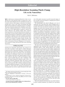
Fig. 2. Diagram illustrating the methods of making cell-attached and inside-out patches (left hand panel) and whole cell and outside-out patches.
currents and in normal size patches are not present in sufficient number to generate a measurable current. In large patches, currents due to exchangers and pumps are well resolved. They are used specifically in the inside-out configuration to permit changes at the cytosolic surface that modify the rate and characteristics of transport measured as the pipette current.
3. Instrumentation of single channel recording A diagram of the essential features of the amplifier used in the headstage of a patch clamp is shown in Fig. 3. Essentially, this amplifier is a current-to-voltage converter which has a high gain, owing to the large feedback resistor Rf, and which is arranged so that the potential inside the pipette, Vref, may either be held at a steady level or changed in a step-wise fashion. A description of the patch amplifier is given in Chapter 16, but the following points may be considered here. (i) The input of the amplifier has JFET transistors of low leakage current and noise
58
D. OGDEN AND P. STANFIELD
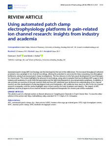
Fig. 3. Schematic diagram of the headstage current/voltage amplifier. The gain (Vo/ip, mV/pA) is set by the feedback resistor Rf, Vo = − Rf · ip + Vref Vref is composed of the sum of Vhold, Vnull and Vcommand, and is subtracted from the output at a later stage.
level. The experimenter needs to take care to avoid damage to these from static potentials, for instance by simultaneously touching an earth when connecting a pipette. (ii) The feedback resistor determines the sensitivity, the background noise level and range of current measurement. If ip is the patch membrane current and (Vout− Vref) the voltage output, − ipRf = Vout − Vref The feedback resistor contributes current noise which decreases inversely with the resistance. As described above, the variance of current noise at bandwidth fc is given by s2 = 4kTfc/Rf It follows that for low noise, high gain recording, Rf should be high, say 50 GΩ. However, since Vout will swing by a maximum of only ±12 V, the output of the headstage will be saturated if ip exceeds 240 pA. In whole-cell recording, currents may often exceed this level. The value of Rf must therefore be chosen to suit the experiment, either by prior selection of a suitable headstage or by using an amplifier that enables the experimenter to switch the value of Rf remotely. Several commercial instruments possess the latter facility. Alternatively, a good compromise may be achieved with a fixed 5 or 10 GΩ resistor for Rf. Capacitor feedback. The noise associated with the feedback resistor is eliminated by using instead a capacitor to feedback current to the inverting input, producing an output that is the integral over time of the pipette current. To correct for this the output is taken via a differentiator stage. The improvement in signal to noise is about
Patch clamp techniques
59
30% when noise from other sources is minimised, a worthwhile improvement for high resolution single channel recording. The disadvantage is the need to discharge the voltage on the capacitor as the output voltage limit of the amplifier is approached, producing a reset transient which, although brief (50 µs) may occur frequently with large standing currents such as those encountered in whole-cell recording. (iii) The potential in the pipette is equal to Vref. This potential is set for zero current by offsetting electrode potentials at the beginning of the experiment. This can be done either manually or by using the ‘search mode’ or ‘tracking mode’ of the patch clamp amplifier, which uses an integrator to keep the current at zero, adjusting Vref accordingly. Once a high resistance seal is obtained, and the amplifier is switched to its voltage clamp mode, Vref may be changed without causing large currents between pipette and bath, (such as those that occur with the ‘loose-patch’ method). Changing Vref will change the patch membrane potential. Most patch amplifiers possess a 10turn potentiometer, labelled VHOLD or VPIP, which allows the holding potential of the patch to be altered. Pulses from an external source (VCOMMAND) may be used to change Vref in a step-wise way. Generally, since noise applied to the headstage with the command signal appears in the current trace, the command voltage (and the noise applied with it) is divided 10- or 50-fold in the headstage, requiring a command pulse 10- or 50-fold larger than the pipette potential but with better signal/noise. (iv) Fast changing commands, such as the leading edges of rectangular pulses, give rise to large currents due to charging stray capacitance associated with pipette and cell. These may saturate the amplifier and must be offset by adjustment of compensation circuits. Separate compensation is usually provided for ‘fast’ (primarily stray) and ‘slow’ (cell) capacitance. (v) Particular attention needs to be paid to earthing and screening. The signal earth point of the amplifier should attach directly to the principal earth point of the set-up. The earth (or ground) socket on the headstage is connected within the cable to the signal earth in the patch clamp amplifier and is for connexion of the bath electrode. All metal surrounding the bath (baseplate, manipulators, dish holders, etc) and the microscope stage, nosepiece, objectives and condenser should have low resistance (10 MΩ resistance suitable for cellattached recording, of 6 or more low resistance pipettes suitable for whole cell recording. This procedure is useful particularly when setting up a pipette puller.
62
D. OGDEN AND P. STANFIELD
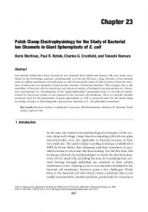
Fig. 4. Two-stage pull of patch pipettes.
Coating pipettes to reduce capacitance Pipettes used in single channel recording are usually coated to thicken their walls and reduce capacitance to the bath solution. There are two reasons for wishing to minimize this stray capacitance. First, high frequency noise levels are reduced and secondly, as mentioned above, capacity currents associated with stepping the potential of the inside of the pipette are also reduced. The r.m.s. current noise associated with stray input capacitance is given by si = 2πfc.C.sV where s is the r.m.s. noise for current (i) and voltage (V), fc is the bandwidth, and C the total capacitance from input to earth. Current noise increases in proportion with voltage noise as the recording bandwidth is increased and also with the capacitance. The current needed to charge the stray capacitance on changing the pipette potential is given by i = C.dV/dt, and will be particularly large for a fast potential step. If at the leading or trailing edge of such a step dV/dt = 100 mV/20 µs, the current needed to charge a stray capacity of 10 pF will be 50 nA. Since a headstage with a 50 GΩ feedback resistor will be saturated by a current that exceeds 0.24 nA (see above), saturation would occur and important information about channels that are rapidly activated by the voltage step would be lost. Generally the fast capacity compensation circuits of patch amplifiers have a range too small to compensate fully pipette capacities larger than 10 pF.
Patch clamp techniques
63
Fig. 5. Patch pipette before and after coating with Sylgard and curing.
Most of the stray pipette capacitance arises across the pipette wall between the pipette and the bath solution. It can be reduced by coating the pipette with a thick layer of Sylgard 184, an inert, hydrophobic, translucent elastomer resin rapidly cured by heating. The coat both thickens the wall of the pipette and reduces the area of capacitance coupling by preventing the bath solution creeping up and wetting the pipette. Coating should run from close to the tip (preferably closer than 250 µm) and continue up the pipette well past the beginning of its taper. The procedure for coating pipettes and curing the Sylgard is illustrated in Fig. 5. As an alternative to Sylgard coating, pipettes can be dipped with backpressure before filling into a molten mix of ‘Parafilm’ in mineral oil (or some other molten wax) or after filling immersed in a silicone coating such as ‘Sigmacote’. Both these procedures prevent fluid contact up the shank of the pipette and thicken the wall at the tip. It is best to observe two additional measures to reduce stray capacity. First, the depth of bath solution in contact with the pipette wall should be minimized. Secondly, the pipette holder should be kept free of excess fluid; often it is helpful to dry the holder with compressed air or N2 before inserting a new pipette. A discussion of methods for low-noise recording is given by Rae & Levis (1992).
5. Formation of a gigaseal As the pipette is advanced through the surface of the bath solution, slight positive pressure is applied to the inside of the pipette to keep the tip free of contamination, either by mouth or from a manometer (a water-filled U-tube that permits fine pressure adjusment by changing the pressure head of water). The current is set to zero, either by altering Vref manually with the Vnull control or by using the search mode of the amplifier. The pipette resistance is then monitored by measuring the current in response to 0.1 to 0.5 mV step-changes in Vref. Contact with the cell is indicated by a rise in pipette resistance. Gentle suction (5-20 cm of water) is now applied to the pipette, when a seal should be formed. Seal formation may occur immediately, or it may take some while to happen. It may be helped by polarisation of the pipette to around −40 mV once a high resistance has developed.
64
D. OGDEN AND P. STANFIELD
A fresh pipette should be used for each attempt to make a seal. The process of seal formation can be observed with good microscope optics. Gigaseals may form immediately on contact with the cell surface with very little negative pressure, particularly with high resistance pipettes. In these cases the profile of the membrane is flat within the pipette tip. More often an Ω-shaped region of membrane is drawn into the pipette tip and the seal forms initially slowly and suddenly achieves a high value. Photographs are given of membrane-pipette seals by Sakmann & Neher (1983). Milton & Caldwell (1990) report the formation of a bleb of membrane lipid in the pipette tip based on microscope observations of seal formation and propose a role for the bleb in forming gigaseals. Sokabe & Sachs (1990) give a microscopic analysis of the pressure/area relations of membrane patchs. Giant patches Hilgemann (1989, 1990, see Collins et al. 1992) reports the use of various hydrophoboic mixtures to facilitate the formation of seals with large tipped pipettes. These include viscous Parafilm/oil mixtures and α-tocopherol. With minimal suction, these agents promote the formation of flat stable seals desirable for access to the inner surface of inside-out patches. Liquid junction potentials Where differences in ionic composition exist between pipette and bath solution, a correction must be applied for the junction potential across the boundary between the two solutions. This potential arises from differences in concentration and mobility of the ion species in the two solutions and maintains electroneutrality across the boundary between the two solutions. The magnitude depends on the relative mobility and concentration gradient of ions diffusing in the two directions and, depending on the solutions used, may be 2-12 mV in physiological solutions. The error arises because the potential will be present when pipette current is zeroed before sealing, but when the seal is made the concentration gradients form part of the driving potential for ion movement, leaving the applied offset potential still imposed in the pipette. With reference to Fig. 3, the initial sequence of steps made during patch recording are as follows. (i) Zero current output of the amplifier is checked with the pipette out of the bath - this is usually zero volts. (ii) The pipette is put in the bath solution and an offset current flows as a result of asymmetries in the AgCl half cell potentials, the junction potentials across the pipette tip to bath and bath into the reference electrode salt bridge, and any voltage on the amplifier Vref. For present purposes, suppose that the AgCl potentials are equal and opposite and the reference junction potential is zero, and so do not contribute. The current flowing into the pipette is driven by the difference between bath potential and pipette potential and is set to zero by adjusting Vref (which sets the pipette potential with respect to the bath). In most patch amplifiers, this is done with a ‘Null’ potential control that changes Vref without registering on the voltage monitor. This value of Vref is taken as zero holding potential and is the zero current potential of the pipette with respect
Patch clamp techniques
65
to bath potential. However, by convention the polarity of the junction potential is bath minus pipette, opposite to the polarity of the Vref potential applied in the pipette. (iii) A seal is formed and the liquid junction potential disappears, leaving the pipette potential displaced from true zero by an amount equal to the initial pipette-bath potential difference, opposite in polarity to the junction potential. In a cell-attached or inside-out recording, the potential is on the outside of the membrane and the true transpatch potential is the holding potential minus the initial pipette-bath potential (i.e. plus the conventional junction potential). For whole-cell recording on breaking through, a new junction potential appears between the pipette and cytosol immediately on patch rupture and disappears over the first minute or so as the cell is dialysed with pipette solution, leaving the initial pipettebath potential added to the holding potential (i.e. the conventional junction potential should be subtracted). The error due to the junction potential can be demonstrated and quantified fairly easily. However, it is necessary to have a reference junction that remains at zero when the composition of the bath is changed. This can be done with a 2-3 M KCl solution in the reference salt bridge and stable AgCl wire or pellet provided the junction between salt bridge and bath is continuously renewed by slow outflow of KCl; for example from a blunt pipette some distance from the recording site (see Neher, 1992; also Chapter 1). Zero junction potential is set at the recording pipette by having the same solution in the bath as would be in the pipette during an experiment. The potential is measured at zero current, either in voltage clamp or current clamp, and set to zero. The bath is changed to another solution (e.g. external solution) and the change in zero current potential measured. This is the excess potential that would be present in the pipette after seal formation and should be subtracted from the holding potential in cell attached or added in whole cell to give the real membrane potential. This problem is reviewed, with particular reference to patch clamp recording, by Barry & Lynch (1991) and by Neher (1992). The polarity has been given the convention bath-pipette, opposite to that determined in the experiment above. The junction potential can be calculated from the Henderson equation (given e.g. in Barry & Lynch, 1991) if the activities and mobilities of the ions are known. As an example, in the simple but common case where the bath contains a 150 mM NaCl solution, while the pipette has an equal concentration of KCl, the junction potential can be predicted from: Ej.p. = (RT/F).ln[(uK + uCl)/(uNa + uCl)] where uNa, uK, and uCl are the mobilities of Na+, K+, and Cl− and Ej.p. is the junction potential, bath relative to pipette. Ej.p. has in this case a calculated value of +4.3 mV, so the pipette will have an excess potential of −4.3mV with respect to the bath. In whole-cell recording, zero mV imposed in the pipette will be −4.3 mV; in cellattached recording zero will be +4.3 mV. In cases where solutions differ more, particularly with Cl− ion replacement, the junction potential can be calculated with equations and ion mobilities given by Barry & Lynch (1991) or taken from the measured values given by Neher (1992).
66
D. OGDEN AND P. STANFIELD
Further problems arise when junction potentials occur at the reference/bath solution junction. It is usual to have a salt bridge of NaCl bath solution between the reference AgCl electrode and bath. This has no junction potential into the bath unless the external solution is changed, when a potential may arise and add to the holding potential. Procedures for measuring liquid junction potentials and discussion of more complex effects seen with external cell perfusion by dissimilar solutions are given by Neher (1992). A second, but less common problem, is that salts of low solubility product (e.g. calcium or barium phosphates, fluoride or sulphate) may precipitate at the interface of pipette and bath solutions.
6. Choice of preparation The choice of cell to use for single channel work depends ideally on the experiment that is envisaged. In practice, the choice of preparation can hinge on whether its cells readily make seals with glass and on the density of ionic channels in the membrane. Preparations that are used include cells from adult tissues, cultured cells, channels in membranes of native lipid, and channels reincorporated into artificial bilayers as large vesicles. Adult cells These have to be cleaned of connective tissue and extracellular matrix, using enzymes such as collagenase and proteases. When dissociating tissues, the presence of DNAse helps prevent clumping; however, individual protocols for enzymatic dispersal are empirically determined. In CNS tissue slices, the cell surface can be cleaned by irrigation from a ‘cleaning’ pipette, and this procedure is increasingly applied to other tissues. The channel density is often very high in adult tissue - sodium channels may have a density of 100 µm−2 or more - making it impossible to isolate a single or small number of channels. Cultured cells These provide the most widely used preparation for single channel recording. Channel density is often lower than in adult cells, and the membrane may have less extracellular matrix. Commonly used primary cultures include myotubes and explant neuronal cultures grown from new-born rats or mice, from Xenopus larvae and from invertebrates. Various cell lines which provide convenient models for physiological processes are also widely used. Channels in native lipid membranes Large liposomes or vesicles have been developed using freeze/thawing of
Patch clamp techniques
67
microsomes (Tank, Miller & Webb, 1982) dehydration/rehydration procedures (Keller & Hedrich, 1992) or KCl and water loading of cells, coupled with protease treatment (Standen, Stanfield, Ward & Wilson, 1984). Reincorporation Lipid membranes can be formed on the tips of patch pipettes and channel reincorporated into these bilayers from microsomes (Coronado & Latorre, 1983 see Chapter 5). Such a method is particularly useful in the investigation of channels in specific membrane fractions. For example, this and related methods can be used to investigate channels in membranes of the transverse tubular system of muscle fibres or in intracellular membrane systems such as sarcoplasmic reticulum and endoplasmic reticulum.
7. Cell-attached recording This mode of recording is used to study single channel currents. The resolution of such unitary currents should be optimized by observing the precautions detailed above for reducing stray capacitance. Good mechanical stability and freedom from vibration are needed to keep cell-attached patches for long enough to record sufficient data. Activation of channels operated by binding of transmitters may be produced by having a suitable concentration of transmitter or agonist in the patch pipette. Opening of voltage-activated channels may be achieved by stepping the potential inside the pipette. Often the pipette solution will have the same ionic composition as the bath solution; substitution of ions may be made for studies of permeability properties of channels. The membrane potential of cell-attached patches (Vpatch) is determined by that of the cell interior (Vcell) as well as by the pipette (Vref). The membrane potential is therefore: Vpatch = Vcell − Vref Generally, Vcell is not known. Sometimes, for example in large cells such as skeletal muscle fibres, it is possible to record this potential with an impaling microelectrode. Suitable analogue means may be used to subtract it from Vref, so that Vpatch is the quantity monitored. Breaking the membrane patch at the end of the experiment with strong suction, so that the pipette is in contact with the cell interior, can also be used to obtain an indication of Vcell. Examples of currents through nicotinic receptors, activated by acetylcholine, are shown in Fig. 6. Fig. 7 shows unitary potassium currents through delayed rectifier channels of skeletal muscle, activated by a depolarizing step. In these records, outward membrane currents are shown as upward deflections since they are, by convention, positive quantities. Most commercial patch clamp amplifiers are
68
D. OGDEN AND P. STANFIELD Rat endplate −110 mV 12°C
5 µM ACh
50 µM ACh
5 pA
500 µM ACh 500 ms
Fig. 6. Cell-attached recording of inward single channel currents activated by acetylcholine in the pipette solution at the rat skeletal neuromuscular junction. Potential −110 mV. 12°C. Bandwidth 4 kHz. Note the grouping of channel openings into bursts and clusters and the increase in open probability within clusters as the ACh concentration was increased. N. K Mulrine and D. Ogden.
arranged so that current flowing into the pipette (outwards across the membrane of cell-attached patches) produces a negative output. For clarity in description of their experiments, patch clampers should be careful to use the correct convention for membrane currents and membrane potentials. Recording from expressed channels. Ion channels modified by molecular biological procedures and expressed in cell membranes are used to study the relation between structure and function. They can be transfected in cell lines or expressed in Xenopus oocytes by injection of mRNA into the cytosol, or of DNA into the nucleus. Procedures for recording from cell lines are the same as those described above. Recording from oocytes is technically more difficult because of the presence of accessory follicular cells and a vitelline membrane which must be removed to gain access to the plasmalemma. Procedures for treating oocytes for patch recording are described by Methfessel et al. (1986).
Patch clamp techniques
69
Fig. 7. Single channel records of potassium channel currents in skeletal muscle fibre activated by a 55 ms depolarization of the membrane potential from −100 mV to 0 mV. Cell attached recording. Note three levels of current corresponding to simultaneous opening of 0, 1 and 2 channels. Reproduced from Standen, Stanfield & Ward (1985), with permission.
8. Cell-free, excised patches Inside-out patches are made from the cell-attached configuration as indicated in Fig. 2. Pulling off a membrane patch often results initially in the formation of a vesicle of membrane in the pipette tip. The outer face must be broken open, which may be done by briefly taking the membrane through the bath solution/air interface; by exposure to a low Ca2+ solution; or by momentarily making contact with a droplet of paraffin or a piece of cured Sylgard. Once the patch is formed, channels activated or modulated by substances applied to the cytoplasmic membrane face may be studied. Such studies have included investigations of the effects of Ca2+ (Marty, 1981; Barrett, Magleby & Pallotta, 1981; Colquhoun, Neher, Reuter & Stevens, 1981); of catalytic subunit of protein kinase (Shuster, Camardo, Siegelbaum & Kandel, 1985); and of ATP (Noma, 1983; Spruce, Standen & Stanfield, 1985). Outside-out patches are formed after breaking into the cell with the procedure
70
D. OGDEN AND P. STANFIELD
indicated in Fig. 2. Such patches have been used by a number of workers for the study of the pharmacology of channels activated by transmitters or hormones (Hamill, Bormann & Sakmann, 1983; Gardner, Ogden & Colquhoun, 1984; Nowak, Bregestovski, Ascher, Herbert & Prochiantz, 1984; Cull-Candy & Ogden, 1985). This configuration of the cellfree mode often has the disadvantage of a higher level of background noise, probably because of a lower resistance of the seals achieved and because of the larger area of membrane in the patch. Further it has been reported that channel kinetics may differ when recorded in outside-out, excised patches from those found in cell-attached recording (Trautmann & Siegelbaum, 1983; Fernandez, Fox & Krasne, 1984). Fast concentration changes. To study neurotransmitter-activated channels, it is important to be able to apply the neurotransmitter on a timescale similar to that encountered in the synapse, within 1 ms. This can be achieved with outside-out patches because of the very narrow unstirred layer of solution adjacent to a patch when compared to that surrounding a whole cell, where solution changes require tens of milliseconds. Methods for fast, submillisecond, concentration changes have been described by Maconochie & Knight (1989) and Lui & Dilger (1991) utilising electronic valves, and with piezo driven stepping of a stream of solution onto the pipette tip by Dudel, Franke & Hatte (1990).
9. Whole-cell recording Whole-cell recording is achieved by rupturing the patch of membrane isolated by the patch pipette, which brings the cell interior into contact with the pipette interior. The process of whole-cell recording is as follows. After forming a gigaseal, the fast capacity transients associated mainly with pipette capacitance to the bath are compensated. Next, the potential of the pipette interior (Vp) is adjusted to a level similar to the anticipated membrane potential of the cell. Rupture of the membrane patch is achieved by applying strong suction or sometimes brief voltage transients, and the process is conveniently monitored by applying test pulses of 1 to 5 mV amplitude. Rupture is indicated by the sudden appearance of large capacity transients at the leading and trailing edges of the pulse. The sequence of changes is shown in Fig. 8. Series resistance errors in whole cell recording The equivalent circuit used to represent the whole-cell recording condition is illustrated in Fig. 9. Current in the pipette, defined for whole-cell recording as positive flowing from pipette to cell, flows first through a resistance in series with the cell membrane to represent the pipette tip. If this series resistance is Rs and the pipette current is ip, a potential difference pipette − cell of amplitude ipRs results. This potential needs to be subtracted from the command potential to yield the cell potential. The series resistance compensation present in commercial patch clamps allows a fraction of ipRf to be added to the command to partly correct the error.
Patch clamp techniques
71
Fig. 8. (a,b) Transient currents due to stray (pipette) capacitance in a cell-attached record before (a) and after (b) cancellation with Cfast and τfast. (c) Transients due to cell capacitance in a whole cell recording with 5 mV rectangular input to Vref. 2 kHz bandwidth. The cell capacitance was 4 pF.
The pipette current has two components, one ionic (=Vc/Rc) and the other capacitative (=C.dVc/dt). The time course of the change in the potential of the cell, Vc(t), from its initial value Vc(0) is given by: Vc(t) = {Vc(0) − Vc(∞)}{1 − e−t/τ}. Vc changes on an exponential curve of time constant τ = C.RsRc/(Rs+Rc), usually approximated well by τ=C.Rs because Rc»Rs. This time constant characterizes the response of the voltage clamped cell not only to applied voltage steps, but also to currents originating in the cell membrane, which are therefore effectively low pass filtered with a bandwidth fc = 1/(2πτ). The time course of the current following a sudden change of Vp, also shown in Fig. 9, has a declining exponential timecourse. Initially current flows mainly into the capacitance. Since Vc(0) is steady at the beginning of the step in Vp, the initial pipette
72
D. OGDEN AND P. STANFIELD
current flowing into the cell discharges the capacitance and is given by ip(0)=Vp/Rs. The pipette current declines exponentially with τ=C.Rs to a steady level. The size and time constant of the error voltage due to series resistance is minimized simply by keeping Rs as small as possible by using low resistance pipettes. If the last condition is kept (and it may be expected to hold in most conditions), τ=RsC and for small currents Vc(∞)=Vp . When using whole-cell recording, it is important to know the errors that arise from series resistance and cell capacitance. These quantities may be estimated from the current transients shown in Figs 8 and 9. Provided Rs«Rc, the area of the transient, which gives the charge on C, is equal to C.Vp, while the time constant of the decline is given by τ=RsC. The area may be estimated by digitizing the current record and integrating, the time constant by curve fitting. Estimates of Rs = Vp/ip(0) from the initial amplitude of the transient are subject to error because the rise of Vp usually has a time course of 10-20 µs and because of low-pass filtering. Typical values of the series resistance are 3-20 MΩ if low resistance (1-5 MΩ) pipettes are used. The resistance may be as high as 50 MΩ, however, and is liable to frequent fluctuation during recording. For a series resistance of 10 MΩ and a cell capacity of 12 pF (corresponding to a spherical cell of 20 µm diameter of membrane capacitance 1 µF.cm−2), τ=120 µs for settling of the clamp and fc=1.3 kHz. The currents associated with charging the cell capacitance should be compensated, using the ‘slow’ capacity compensation of the patch clamp amplifier. This system injects current into the pipette to cancel the capacitative currents, avoiding saturation of the headstage during large voltage pulses. In most patch clamp amplifiers, the slow capacity compensation is separately switched, and has controls for the size of the capacitance and the time constant (or series resistance) of the decline of capacity currents. It is important to note that capacity compensation subtracts capacity current from the amplifier output. It does not compensate for the slow change in cell membrane potential due to series resistance. Most commercial amplifiers have separate series resistance compensation which allows a fraction of the pipette current times series resistance to be added to the command voltage as in conventional voltage clamp (see Chapter on voltage clamp techniques). This works best if Rs is small and should be used with caution because of frequent fluctuations of Rs during recording, to the extent that the best procedure is to monitor and adjust the compensation digitally via an interface immediately before each voltage command. A second way of dealing with series resistance in whole-cell recording is to use a switched (discontinuous) single electrode voltage clamp in which the membrane potential is monitored at zero current flow, so eliminating the error voltage due to ip (see Chapter 2). Switched clamps have inherently greater noise, 10-100 fold, than patch clamps and can only be used with large membrane currents. Diffusional exchange between pipette solution and cytosol In conventional whole-cell recording, the contents of the interior of the cell come into diffusional equilibrium with the solution in the patch pipette. It is achieved
Patch clamp techniques
73
ip
Fig. 9. (a) Equivalent circuit of whole cell recording. Current im flows in the cell resistance Rc and ic in the capacitance. Pipette current, ip=im+ic, flows in the series resistance Rs between pipette and cell and produces a voltage error Vp−Vc=ipRs. (b) Time course of changes of Vc and ip following a step of Vp. Rc Vc = Vp –––––– (1 − e−t/τ) Rc + Rs Vp Rc ip = –––––– + Vp –––––––––– e−t/τ Rc + Rs Rs(Rc + Rs) τ = Cm . RsRc/(Rs + Rc) Vc(∞) = VpRc/(Rc + Rs) ip(0) = Vp/Rs
ip(∞) = Vp/(Rc + Rs).
more rapidly for ions than for large intracellular molecules, which do, however, get washed out of the interior of the cell in time. The time course of exchange depends on the size of the pipette tip and the cell volume, as well as on the molecular size and the degree of buffering by cytoplasmic constituents. The advantages are control of the intracellular ionic composition and the perfusion into the cell of agents such as dyes that indicate ion concentrations, second messengers and ‘caged’ second messengers, antibodies to intracellular proteins and small proteins generally. The disadvantage is the loss of important cellular components, including small proteins, into the pipette. The time course of equilibration of Na+ ions during whole-cell recording was reported by Fenwick, Marty & Neher (1982) to have a time constant of about 5 s in chromaffin cells, judged by changes in the Na current. Junction potentials due to small ions will exist between pipette solutions and the cytoplasm. This source of error will not be a constant, but will change towards zero as equilibrium between pipette and cellular contents proceeds. Marty & Neher (1983)
74
D. OGDEN AND P. STANFIELD
estimate a maximum error of 12 mV from this source. A displacement of the potential dependence of ionic currents that occurs during whole-cell recording may be related to this changing junction potential. The time course of equilibration of larger molecules is much slower, particularly if they bind to cellular components or are metabolised. For molecules such as fluorescent dyes of mass number 500-1000 Da equilibration, judged by the fluorescence increase, takes several minutes, and depends very much on how good the access is through the pipette tip. Observation suggests that as well as a low access resistance it is important to minimise the amount of material taken into the pipette tip during seal formation. An analysis of the time course of equilibration of dextrantagged dyes as a function of size and access resistance has been made by Pusch & Neher (1988). They present evidence that components of upto about 20 kDa may be lost from the cell. There are well documented instances of changes in the properties of ionic currents, and also cell responses involving second messengers, that occur during whole cell recording and which can be attributed to loss of cytosolic components into the pipette. Best known is the rundown of slowly-inactivating Ca conductance that occurs during intracellular perfusion. Evidence suggests that this is slowed by inclusion of ATP and Mg in the pipette, and may be improved by inclusion of protease inhibitors such as leupeptin or phosphatase inhibitors. Loss of the calcium mobilising hormonal response of exocrine cells during conventional whole cell recording was noted by Horn & Marty (1988) who introduced the method of patch permeabilisation to prevent rundown of the responses. Instead of rupture by pressure of the membrane under the pipette they achieved electrical access to control the membrane potential by including the Na-ionophore nystatin in the pipette solution, preventing loss of high molecular weight components. The method has been used with other ionophores, such as amphotericin, and a bacterial toxin (α-toxin from Staph. aureus, Khodakhah et al. 1992) that makes pores large enough to admit dyes and ‘caged’ second messengers