viewed as queries that are applied against an entity-relation graph that represents ..... Each composite node is expanded into a pattern-region2. %. ¡ , and each ...
Pattern-based Software Architecture Recovery Kamran Sartipi
�
Kostas Kontogiannis
�
University of Waterloo � School of Computer Science and, � Dept. of Electrical & Computer Engineering � Waterloo, ON. N2L 3G1, Canada ksartipi, kostas � @swen.uwaterloo.ca Abstract This paper presents a technique for recovering the high level design of legacy software systems based on pattern matching and user defined architectural patterns. Architectural patterns are represented using a description language that is mapped to an attributed relational graph and allows to specify the legacy system components and their data and control flow interactions. Such pattern descriptions are viewed as queries that are applied against an entity-relation graph that represents information extracted from the source code of the software system. A multi-phase ��� search algorithm with a bounded path-queue mechanism controls the matching process of the two graphs by which, the query is satisfied and its variables are instantiated. An association based scoring mechanism is used to rank the alternative results generated by the matching process. Experimental results of applying the technique on the Xfig system are also presented.
1
Introduction
Legacy software systems are mission critical, large, and complex systems that are operational for approximately 10 to 15 years [17]. Due to prolonged maintenance such legacy systems are difficult to maintain, evolve, or integrate and in most cases their architectural design deviates from the original design. In this context, architectural recovery is a key activity in supporting maintenance tasks such as reengineering, objectification, or restructuring. In a nutshell, the approaches to software architectural recovery can be classified as clustering-based techniques and pattern-based techniques. The clustering-based techniques generate architectural components by gradually grouping
� This work was funded by IBM Canada Ltd. Laboratory - Center for
Advanced Studies (Toronto) and the National Research Council of Canada.
the related system entities using a similarity measure [12, 18, 4]. On the other hand, the pattern-based techniques first compose a high-level mental model of the system architecture (also known as conceptual architecture or architectural pattern) using a modeling means such as a query language [11, 10, 14, 9, 8] or a block diagram [7, 13], and then a pattern matching engine searches to identify an instance of the architectural pattern in the software system. The motivation for this research stems from the lack of a reflective and uniform model for pattern-based software architectural recovery, whereby the software system, architectural pattern, and pattern matching process, are all uniformly represented using a graph formalism, and the recovered architecture conforms with detailed constraints of the architectural pattern. The reverse engineering community has paid particular attention to the pattern matching approaches since they allow the use of domain knowledge and system documents in composing the pattern, hence provide a user/tool cooperative environment for architectural recovery. Moreover, the software systems are intuitively represented as graphs and the reverse engineering community is on the verge of adopting a graph standard for information exchange among the existing reverse engineering tools [5]. This paper aims at an approach to software architecture recovery that considers the high-level design of a system as a pattern graph, and models the recovery process as a graph pattern matching problem that matches such a high-level pattern graph of the system with an entity-relationship graph representation of the source-code system entities.
2
Software architecture recovery (definition)
Despite several attempts for automating the architectural recovery process (i.e., clustering) it is generally accepted that a fully-automated technique is not feasible. It is
Off-line: pre-process
Software System C / Pascal / ....
On-line: analysis
Module-Interconnection pattern
- System analysis - Domain & Document - Decision making
AQL query
Parsing
Query generation
AST RSF Software as graph
Architecture
Graph generation
Data mining
Pattern graph Software graph regions & Similarity matrix
Graph matching engine (search & evaluation)
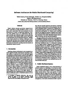
Figure 1. The interactive framework for the proposed pattern-based software architecture recovery. rather difficult to extract the architecture of a large system at once, hence, the architectural recovery should be an incremental process. Software systems usually consist of some sort of patterns in their design which form the basis for the recovery process. Most recovery processes focus on the structural properties of a system, ignoring the high-level behavior of the system. Finally, the role of the user is increasingly important in incorporating the domain knowledge and system documents into the recovery process. Based on the above discussion, this paper defines the software architectural recovery problem as: devising a tractable methodology and the supporting tools for interactively and incrementally recovering a system’s structure using domain and system knowledge.
3
Proposed framework
We propose an interactive reverse engineering framework for incremental recovery and evaluation of the architecture of a software system in the form of cohesive modules (or subsystems) that comply with the constraints of a user-defined pattern. Figure 1 illustrates the different parts of the proposed interactive architectural recovery framework where the thick arrows signify the processes in the framework; boxes represent the different forms of information in the framework; the thin arrows indicate the inputs and output of the graph matching engine; and the user is the high-level decision maker that produces a mental model of the architecture and
verifies the result of recovery. The framework consists of an off-line pre-process phase and an on-line analysis phase. In this framework, the user defines a graph-based architectural pattern of the system modules (subsystems) and their interactions based on: domain knowledge, system documents, or tool-provided clustering techniques. In an iterative recovery process, the user constraints the architectural pattern and the tool provides a decomposition of the system entities into modules or subsystems that satisfy the constraints. The architectural pattern can be viewed as a graph of modules and interconnections1, where each module (one node of graph) represents a group of placeholders for the system entities (i.e., functions, types, variables) to be instantiated, and each bundle of interconnections (one edge of graph) between two modules represents data-/controldependencies between two groups of placeholders in two modules. The minimum/maximum sizes and the types of both placeholders and the interconnections are considered as free parameters to be decided by the user (respecting the allowed relation between two entities). This yet un-instantiated module-interconnection representation (can be referred to as conceptual architecture) is directly defined for the tool, using a proprietary language that we call Architecture Query Language (AQL). Therefore, a query in AQL represents a macroscopic graph-form pattern for a part or the whole of the system architecture to be recovered. The task of the tool is then to search through the software system (again represented as a graph of system entities and relationships) to find an sub-optimal match be1 Similarly, at the higher level architecture recovery a graph of subsystems (consisting of files or modules) and their interconnections are used.
tween the module-interconnection pattern in the AQL query and the graph of the system.
3.1
Software system and architectural pattern
In this approach the software system and the architectural pattern are presented using the attributed relational graph notaion defined in [6]. The software system is represented by a source-graph , where the nodes ( ) represent files, functions, datatypes, and variables and the edges ( ) represent call and use relationships. The nodes and edges comply with the specific domain model defined for architectural analysis [16].
�������� ��
����
���
���
��
The architectural pattern is represented by an AQL query that is to be matched against the source-graph . Each module of the query uses one or more entities as fixed entities to appear in the result of the recovery, namely mainseed(s) which determine the corresponding search-space to be searched for the module, and seeds which just appear in the result without search. In the following a part of an AQL query, consisting of a subsystem S1 of files and its interconnection links to other subsystems is shown: BEGIN-AQL SUBSYSTEM: S1 MAIN-SEEDS: IMPORTS: RESOURCES:
EXPORTS: RESOURCES:
CONTAINS: FILES: RELOCATES:
files e edit, e update rsrc ?IR, rsrc ?R1(6 .. 10) S2, rsrc ?R2(12 .. 20) S4 rsrc ?ER, rsrc ?R3(10 .. 15) S2, rsrc ?R4(1 .. 5) S3 file $CFI(7 .. 10), files e edit, e update NO: files e allign, u scale TO: S3
END-AQL
The above AQL fragment is interpreted as: the subsystem S1 which will be instantiated with seven to ten files, and definitely contains the files e edit and e update (main seeds), imports minimum six and maximum ten resources (?R1) from subsystem S2. A similar interpretation holds for the EXPORTS and CONTAINS sections. The notations ?IR and ?ER in the import and export parts denote unidentified quantities of links between the current subsystem and any other subsystems in the query that have not been specified by the architectural pattern, therefore, are not matched by the matching algorithm.
4
Overview of the graph matching process
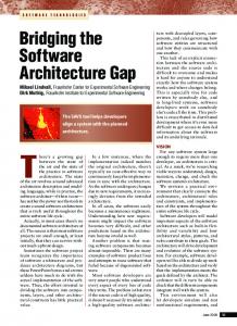
In modeling the incremental graph matching approach for architecture recovery, a number of intermediate graphs and connector edges are defined. Such intermediate graphs allow to represent the architectural pattern and input graph at each iteration of the matching process in terms of their constituents (i.e., a number of recovered modules and their import/export links) and consequently formulate them using recursive graph summation equations. This formulation provides a valuable means for modeling and implementing the whole incremental pattern matching process. In this Section, an overview of the graph pattern matching process is discussed with reference to the framework of Figure 1 and the matching process of Figure 2.
4.1
Step 1: System representation
The software system is parsed and the source-code entities and data/control dependencies are abstracted according to an architectural-level domain model which yields the entity-relationship source-graph . The source-graph provides a search-space for the matching process. However, since even in a medium-size software system the number of entities and relationships that are generated are prohibitively high, any matching algorithm will be intractable. To address this problem, the search space is decomposed using data mining association relation to generate a collection of sub-spaces, where each sub-space is a sub-graph of the source-graph , namely a source-region . Each source-region is distinguished by the main-seed node in that region. In this context, the data mining technique Apriori [3] is used to discover all groups of system entities that are related by maximum association, where maximum association refers to a maximum group of entites that all share the same relations to another maximum group of entities. Every node in a source-region is labeled with an association-based similarity value to the main-seed of the source-region as a means for the matching process to operate on groups of highly associated entities. The group of source-regions ’s in the source-graph are stored in a database and the user selects a source-region from the database to be matched with the incremental part of the pattern at each matching phase ( [1.. No. of modules]). At file-level analysis the source-region nodes are files functions, datatypes, variables, and at function-level analysis the source-region nodes are functions, datatypes, and variables.
��
���
���� �
��
���� �
��� ��
��
� ���
4.2
Step 2: pattern representation
An abstract pattern of modules-and-interconnections for the software system is modeled as a query in the proposed Architecture Query Language (AQL). An AQL query
Phase 2 being matched
Phase 1 matched
11 6
5
1
(c) Input−graph
(d) Matched−graph
7 10 2
9
4
G1
+ ( R2
m
+ (Rm2
1
4
9
13
2
sr
+
G g(2) )
+
G2
I
=
G2
) =
G2
Match m
G2 G1
6
13
m sr
m
5
pr
pr
=
m
G1
p
+ ( Rm2
+, + n2,1 5
6
4
9
n2,3
(b) Pattern−graph
mr
+
mr
G2
)
Graph summations
Source−graph edge
Main−seed
Un−matched edge
n2,2
AQL query F: (2, 4)
Module M1
F:(2, 3) use−F : (1,2)
6
1
l1
Module M2
M1
M2
(a) Representing an AQL query as a Query−graph. The Query−graph generates pattern−graph and input−graph in parts (b) and (c).
Main−seed
Figure 2. The graph pattern-matching process iteratively matches a pattern-graph with an input-graph and yileds a matched-graph as the recovered architecture for the current matching phase.
can be further represented as a query-graph consisting of composite nodes that are linked through composite edges. Each composite node is expanded into a pattern-region2 , and each composite edge is expanded into a group of edge-bundles3 (each edge-bundle is a collection of edges). The pattern-region and edge-bundles are consequently matched against a source-region ( is shown as where and is the current matching phase) and their connector-edges . The rationale for expanding the composite-edges is to allow every subset of the nodes in a source module to be connected to every subset of the nodes in the destination module, according to the constraints modeled in the AQL query.
��
����� � �
� ��� � ��
4.3
�� � � �
� � ���� ���
��� ��
� ���
Step 3: graph matching process
The matching process computes a sub-optimal match between a pattern-graph that originates from an AQL query and an input-graph that originates from the system source-graph. The matching is performed in phases ( is the number of AQL query modules) with the require-
��� �
�
����� �
�
�
2 a pattern-region is generated with maximum number of nodes in the corresponding AQL query module and connect every node in patternregion to every other node in pattern-region that are allowed based on the types of the nodes. 3 each edge-bundle connects every node from a recovered module to one node in the pattern-region with respect to the direction of the composite edge. Initially, the first nodes are of the pattern-region are selected as the sink/source nodes, however during the matching process the common sink/source node of an edge-bundle that is not matched yet can be redirected to another node without any cost.
� ��� �
ment that the obtained results conform with the constraints specified by the AQL query.
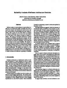
We use the � � search algorithm that is modified by a “bounded path-queue heuristic” to compute a sub-optimal matching cost between the pattern-graph and inputgraph while the AQL query constraints are not violated. The search algorithm generates a search-tree that corresponds to the recovery of each module in AQL query (Figure 3(a)), that consists of: i) a root node for matching the main-seed of the source-region with the first placeholder-node in the pattern-region ; ii) a number of non-leaf tree-nodes at different levels of the searchtree that correspond to different alternative matching of the placeholders in the pattern-region with nodes in the sourceregion; and iii) leaf tree-nodes that correspond to solution paths where the placeholders have been instantiated and constrains have been met. At each node of a search-tree the cost of graph edit operations for matching “a node and its edges” from the source-region with a “placeholder-node and its edges” from the pattern-region are evaluated and the search-tree is expanded from a tree-node that has the minimum cost. Each search-tree has a maximal depth equal to the number of placeholder-nodes in the pattern-region (or equivalently to the maximum number of placeholders in the AQL module ).
�
���
� �
��� �� ��
��
� �����
���
� �� � �
� �
�
A pattern-graph by its definition is composed of a number of smaller patterns (i.e., individual pattern-regions at different matching phases . This composition property allows to manage the complexity of the matching pro-
��
�
Main-seed
n i,1
(1) (2)
(5)
Discarded costly node
n i,2 n i,3 (4)
n i,x Placeholder-node to be matched
System Xfig Clips Apache Bash Elm GSview
(1),(2),(3),(4),(5): Sequence of branching
n i,4 n i,5
(a) A* search tree
Complete path
Phase 2
Search for module M3
Level
Incomplete path
Root
0 1
(1)
Phase 1
Search for module M2
Phase 3
Search for module M1
2
3
KLOC
files 98 44 42 47 62 47
funcs 1662 736 709 1017 420 469
74 40 38 44 35 39
4 Aggr. types 37 54 42 45 19 10
5 Global vars 1356 161 95 365 244 382
2 3
Leaf node
(3)
(5)
(2)
(2), (4): Search-trees that failed to produce result
Solution path (1),(2),(3),(4),(5): Sequence of generating search-trees. (2)
(1) and (4)
(3): Backtracking to previous phase.
(b) Multi-phase search space and backtracking
Figure 3. Demonstration of a multi-phase search strategy using: (a) an � � optimal search algorithm to match the placeholdernodes at each phase and; (b) backtracking between phases.
cess of a large source-graph by applying it on a region-byregion basis. In this form, the whole matching process is divided into incremental phases (as partial-matchings) so that the recovery process performs a multi-phase matching. Each partial-matching at phase ( ) generates a search-tree which is a part of the multi-phase searchspace, illustrated in Figure 3(b).
�
Table 1. Source-code statistics of the six analyzed software systems.
(4)
Tree paths
5
1
Maintained node
(3)
�
� � �� ��� ��� ���� � �
Experiments
In this Section the experimental results of the proposed approach are presented. A comprehensive set of experiments related to the time/space complexity, accuracy, stability, and quality of the architecture recovery technique has been presented in [16]. The proposed technique has been implemented in Alborz [15], a prototype toolkit that aims to recover the architecture of medium size systems implemented in a procedural language such as C. The input to the Alborz tool is an information base that corresponds to the entities and relationships of the software system in the form of an AST or RSF file. The tool provides the result of the architectural recovery into two forms: i) HTML pages for the recovered components, tool generated metrics, and source code, to be visualized by a Web browser such as Netscape;
and ii) graphs of boxes and arrows to be visualized by the Rigi tool [1], where the boxes are the system files or the analyzed components and the arrows are either the resource interaction (i.e., import/export) between the components or their association strengths. The association values among the system files are distributed over a large range of values, hence they can be classified into several sub-ranges, namely “strengths of association” consisting of for sub-ranges of strong, medium, loose, and weak. This classification of values allows to simplify the visualization of the association graph of the system components (i.e., files, modules, or subsystems). The experiments are performed on six middle-size industrial systems, namely: i) Xfig.3.2.3 drawing editor, ii) Clips.4.20 expert system builder, iii) Apache.1.2.4 http server; iv) Bash.2.03 Unix shell; v) Elm.2.5.6 Unix mail system; and vi) Ghostview.3.5.8 postscript file viewer and navigator. Table 1 presents the source-code related characteristics of the experimentation suite. The hardware platform for the experiments consists of a Sun Ultra 10 with 440MHZ CPU, 256M memory, and 512M swap disk. The experiments are performed in a single-user load environment.
5.1
Architecture recovery of Xfig
The Xfig system [2] lacks any documentation on its structure and only the user manual exists. However, a consistent naming convention is used throughout the system files which can be used as an aid for inferring its structure. Figure 4(a) illustrates the generated architectural pattern of the Xfig system with four abstract subsystems and corresponding link constraints. During the incremental and iterative recovery process this pattern yields the recovered architecture in Figure 4(b) where the size constraints for both the subsystems and links have been satisfied. Figure 4(c) and (e) illustrate the file association graph feature of the proposed framework for viewing the Xfig re-
main-seeds
No. of Placeholders
Recovered files + Distributed files
u_elastic u_drag
17 + 6 files 668 funcs
S2
R
3(
66
)
R4(10)
Pattern matching
S3
S5
e_scale
f_readtif
13 + 7 files 327 funcs
10 Phs
(a) Architectural pattern using AQL query
S3
S5
9 + 1 files 54 funcs
(b) Recovered architecture
S1- S4
u_drag
S1-S4
R1(130)
) 00 ..1 40 3( ?R
?R2(40..100)
?R1(50..150) 13 Phs
23 + 14 files 598 funcs
20 Phs
S2
R2(100)
S1-S4
?R4(0..10)
25 Phs
e_edit
(c) Final recovery of Xfig system: the subsystems S1 and S4 are merged into subsystem S1-S4
S2
e_edit
u_elastic
S5
S3 e_scale
f_readtif
rest-of-system
(d) Association links among the resulting subsystems in part (b). Recovered No. of subsystems files
editing & utility & drawing
No. of files
Precision
Recall
47
81%
63% 45% 100%
X-windowing
28
78%
64%
20
editing & utility &
37
65%
31% 39%
S5
10
file manipulation
16
70%
44%
rest-of-sys
8
5 zero size files
S1-S4
37
S2
23
S3
Xfig subsystems:
(e) Adding all association links to part (b)
Xfig subsystems
1) editing: 19 files 2) utility: 18 files 3) drawing: 10 files
4) file manipulation: 16 files 5) X-windowing: 28 files
(f) Arcitectural recovery evalution
Figure 4. (a) The architectural pattern of the Xfig system where the subsystems S1 and S4 have been merged. (b) The recovered architecture where the link constraints have been satisfied. (c) and (d) Graph visualization of the recovered subsystems for the Xfig system using the file association graph and subsystem association graph with “strong” and “medium” association strengths. (e) Viewing all association link strengths. (f) Architectural evaluation using “Precision” and “Recall” metrics.
covered architecture. Figure 4(c) illustrates the result of the recovery process (only the strong and medium association links are shown) where the highly associated files are grouped into subsystem S1-S4 and the association among the subsystems are limited. Figures 4 (e) illustrates the inclusion of the loose and weak association links to Figure 4(b). Figure 4(d) illustrates the association links among the recovered subsystems as a simplified view of the other figures. The subsystem S1-S4 has high association with subsystem S3 but low association with subsystems S2 and S5 as it was aimed for. Also in Figure 4(d) the lines across the boxes for the subsystems S1-S4, S2, and S3 indicate high intra-subsystem association that can be interpreted as the recovery of high cohesive subsystems. Figure 4(f) presents the accuracy of the Xfig recovery process in terms of the Precision and Recall metrics. The subsystem S1-S4 recovers all the drawing files and together with S3 recover almost all the editing and utility files. S2 is allocated to windowing files and S5 recovers file-manipulation files. The obtained Precision and Recall values indicate the accuracy for the proposed pattern matching technique.
6
Conclusion
This paper contributes to the reverse engineering research area by providing an interactive framework for architectural recovery, an incremental graph pattern matching model of the recovery process, and a prototype toolkit to support the proposed methodology. The proposed framework is based on techniques from the areas of data mining, approximate graph matching, clustering, and programming language design.
References
[6] M. A. Eshera and K. S. Fu. A similarity measure between attributed relational graphs for image analysis. In Seventh International Conference on Pattern Recognition, pages 75–77, 1984. [7] P. Finnigan, R. Holt, I. Kalas, S. Kerr, K. Kontogiannis, et al. The software bookshelf. IBM Systems Journal, 36(4):564–593, November 1997. [8] R. Fiutem, E. Merlo, G. Antoniol, and P. Tonella. Understanding the architecture of software systems. In Proceedings of the 4th Workshop on Program Comprehension, pages 187–196, 1996. [9] D. R. Harris, H. B. Reubenstein, and A. S. Yeh. Reverse engineering to the architectural level. In Proceedings of the 17th ICSE, pages 186–195, 1995. [10] R. Kazman and M. Burth. Assessing architectural complexity. In Proceedings of the CSMR, pages 104– 112, 1998. [11] R. Kazman and S. J. Carriere. Playing detective: Reconstruction software architecture from available evidence. Technical Report CMU/SEI-97-TR-010, Carnegie Mellon University, 1997. [12] A. Lakhotia. A unified framework for expressing software subsystem classification techniques. Journal of Systems and Software, 36(3):211–231, 1997. [13] H. A. Muller, M. Orgun, et al. A reverse-engineering approach to subsystem structure identification. Software Maintenance: Research and Practice, 5:181– 204, 1993. [14] G. C. Murphy, D. Notkin, and K. Sullivan. Software reflexion model: Bridging the gap between source and higher-level models. In In proceedings of the 3rd ACM SIGSOFT SFSE, pages 18–28, 1995.
[1] Rigi, URL = http://www.rigi.csc.uvic.ca/rigi/rigiindex.html.[15] K. Sartipi. Alborz: A query-based tool for software architecture recovery. In Proceedings of the IEEE International Workshop on Program Comprehension [2] Xfig User Manual, URL = (IWPC’01), pages 115–116, Toronto, Canada, May http://www.xfig.org/userman/. 2001. [3] R. Agrawal and R. Srikant. Fast algorithms for min[16] K. Sartipi. Software Architecture Recovery based ing association rules. In Proceedings of the 20th Interon Pattern Matching. PhD thesis, School of Comnational Conference on Very Large Databases, pages puter Science, University of Waterloo, Waterloo, ON, 487–499, 1994. Canada, 2003. [4] N. Anquetil and T. C. Lethbridge. Experiments with clustering as a software remodularization. In Proceedings of the Sixth Working Conference on Reverse Engineering, pages 235–255, 1999. [5] Bell, IBM. Workgroup on Standard Exchange Format (WoSEF), Limerick, Ireland, June 06 2000.
[17] E. Wallmuller. Software Quality Assurance: A Practical Approach. Prentice Hall, New York, 1994. [18] T. A. Wiggerts. Using clustering algorithms in legacy systems modularization. In Proceedings of the Fourth Working Conference on Reverse Engineering, pages 33–43, 1997.