Proceedings of 2005 Particle Accelerator Conference, Knoxville, Tennessee
PC-LabView BASED CONTROL SYSTEM IN SAGA-LS H. Ohgaki#, Institute of Advanced Energy, Kyoto University, Kyoto, 611-0011, Japan Y. Iwasaki, S. Koda, Y. Takabayashi, K. Yoshida, T. Tomimasu, SAGA Light Source, Tosu, 841-0002, Japan H. Toyokawa, National Institute of Advanced Industrial Science and Technology, Umezono 1-1, Tsukuba, Ibaraki 305-8568, Japan
Abstract A control system of SAGA Light Source (SAGA-LS) has been constructed and operated during the machine commissioning. The system consists of off-the-shelf IO devices, FieldPoint (National Instrument), and PLCs, FAM3 (Yokogawa), directly connected to the local server PCs (PC-IOCs) via Ethernet. The communication protocol between server and client is the simple Channel Access protocol emulated by ActiveX CA. The applications have been developed by LabView. About 1,500 process variables are employed to control about 500 control objects, such as the magnet power supplies, the RF control, vacuum monitors, BPM data, and LCW data. The system performance has been achieved at the communication rate of -5 Hz. MySQL database system archives data to assist daily operation and to display the historical trend of the machine. The database applications have also been developed by LabView.
INTRODUCTION The SAGA synchrotron light source (SAGA-LS) is a medium size third-generation light-source, which is under operation of the SAGA prefecture [1]. The construction of the facility building started in fall of 2002 in Tosu, Saga Prefecture. The installation of the injector linac and the storage ring started in the fall of 2003. The commissioning has started on the summer of 2004. We succeeded in acceleration with linac in August 30, 2004 and also achieved the first storage in the storage ring in November 12, 2004. Because of the restricted number of the in-house-staff and limited amount of the budget for the construction, the control system for SAGA-LS should be simple and robust, easy to develop, maintain and expand. The use of the offthe-shelf products and PC is the only solution to this issue. The PC control systems are commonly used in many facilities [2] because of their high cost performances. On the other hand, there are sophisticated and wellestablished control systems based on workstations, such as EPICS, which have been used in many large accelerator facilities. Since EPICS system runs on a PCUNIX system, a UNIX PC-based EPICS system is one of a typical control system. However, it is difficult to implement and expand the EPICS system without EPCIS expert. Fortunately, the number of the control object of
the SAGA-LS is about 500 and there are very few demands for real-time control, at least during the commissioning stage. So, we designed a Windows PCbased control system which only uses the EPICS channel access (CA) [3]. There are many excellent works to develop CA components for the PC-Windows environment [4]. ActiveX CA [5] is one of such the components. Although the ActiveX CA is not fully functioned EPICS, a PC with the ActiveX CA server and off-the-shelf IO devices works as a regular IOC PC IOC) [6]. LabView is one of the easiest environments for software development. As we need daily update of the control application during the commissioning, the inhouse modification is a crucial issue. So our choice of the control system for the SAGA-LS was LabView-ActiveX CA. Because the data communication protocol is subset of the EPICS CA, we can use the existing EPICS tools. Furthermore, the system can be upgraded to the standard EPICS system seamlessly, if higher performance and/or real-time processing will be required. In this paper, we will describe the system outline of the present system.
㧔 㧙
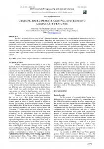
SYSTEM OUTLINE SAGA-LS control system consists of PC-IOCs directly connected to the off-the-shelf IO devices, console PCs, and 100M-LAN. Fig.1 displays the schematic drawing of the system. As is shown in the figure, the system can be separated in the six interface-layers. From top to bottom, the layer corresponds to the facility LAN layer, operator interface layer, machine LAN layer, device interface layer, Facility LAN
BL users
BL users
BL users
Database CA client
Linac Magnet
Console PCs CA server
CA client
Machine LAN
Control objects
CA client
CA client
ActiveX CA Linac Vacuum Monitor / LCW CA server
PC-IOCs
IO devices
CA client
Ring Magnet CA server
Ring Vacuum & BPM CA server
Ring RF CA server
FP-1601
FP-1601
PLC FA-M3
FP-1601
PLC FA-M3
PLC FA-M3
Linac Magnet
Linac Vaccum
LCW
Ring Magnet
Ring Vacuum
Ring BPM
Ring RF
_____________________________________________
#
[email protected]
Figure 1: Schematic view of the SAGA-LS control system. c 0-7803-8859-3/05/$20.00 2005 IEEE
3976
Proceedings of 2005 Particle Accelerator Conference, Knoxville, Tennessee
IO device layer, and control object layer. At present stage, the control objects are 1) magnet power supplies both for injector linac and for ring, 2) vacuum monitors, 3) beam position monitors in the storage ring, 4) ring RF system, and 5) the low conductivity water (LCW). Total number of the control object is about 500 at present stage. This number will increase in the normal operation stage. Following section we will describe the detail of the present system.
PC-IOC A PC with slot IO cards is the most cost effective IO device and this configuration works as a stand-alone PCIOC [7]. However, there are several problems in this configuration. First, reliability of the slot IO card is not high. Second, the system must be updated in accordance with the version update of the OS which follows the hardware drivers update procedures. So, we chose the industrial IO device which is reliable, ready-to-use, and stand-alone one. The product lifetime of the industrial IO device is usually longer than that of the slot IO card. Recent industrial IO devices have Ethernet modules and work as IOC. So, they can be directly connected to the LAN. However, as is shown in fig.1, we put PCs between the machine LAN and the IO device 1) to convert the IO device parameter into the physical one, 2) to hide the IO devices from the LAN to secure the control object from outside, 3) to use a PC as a local controller for the maintenance of the control object. FieldPoint (National Instruments) is used for the IO devices, because of its reliability, hot plug and play operation, and good connectivity to the software environment, LabView. While FA-M3 PLC (Yokogawa Co., Ltd.) is employed for the magnet control both for the injector linac and for the storage ring, because we need a 16-bits resolution for the main magnet power supplies and the synchronous ramping from injection energy (250 MeV) to operation energy (1.4 GeV) within a few minutes. There are 5 PCs (2.66 GHz) running on the Win2k for the PC-IOC. As the PC-IOC works as a local control machine for the maintenance, i.e. repairing or conditioning and so on, the PC-IOCs are located close to their control objects. The ActiveX CA server applications running on the PC-IOC are developed by LabView. All of the control applications have been developed in the facility. Figure 2 shows a snapshot of the desktop window during the development of the CA server for the magnet power supply of the ring. The PLC control programs were developed by Techno-AP (Ibaraki, Japan).
Console PC and Machine LAN The data communication between the PC-IOCs (server) and the console PCs (client) is done via 100 Mbps LAN, which is isolated from the facility LAN and also isolated from the beam-line users. As is shown in figure 1, beamline users will get the machine status via database system. There are 8 Windows2000 PCs (2.66 GHz) running for the console PCs in the control room. A few notebook PCs
Figure 2: Snapshot of the desktop window of the CA server development.
Figure 3: Snapshot of the desktop window of the CA client development.
were used as the console PCs in the control room, also. The ActiveX CA client applications were developed on LabView. Figure 3 shows a snapshot of the desktop window during the development of the CA client for the magnet power supply of the ring.
ActiveX CA As the ActiveX CA only supports the polling data transfer method, the communication rate between client and server is mainly limited by number of the process variable (PV). Furthermore, we must combat with the data-synchronous problem in the multi-client system. To resolve the problem we use “SET VALUE” and “READBACK VALUE” for “CA put.” The “SET VALUE” is changed only by the client side and referenced in the server. On the other hand, the “READBACK VALUE” is periodically published from the server side. Figure 4 shows the PV configuration of the magnet control system where “CA put” and “CA read” are used. Consequently, the PV number in the magnet
3977
c 0-7803-8859-3/05/$20.00 2005 IEEE
Proceedings of 2005 Particle Accelerator Conference, Knoxville, Tennessee Mode set (injection, ramp up, shut down, tuning) CA put Mode
Mode mask CA read
CA server
switch event driven
CA read
knob
SET VALUE CA put
READBACK VALUE
event driven 2 Hz
CA read
PLC controller
value
MONITOR VALUE CA read
2-5 Hz
CA clients
magnet
Figure 4: PV configuration of the magnet control system using ActiveX CA.
control system of the ring is about 700 including control flags which are also shown in figure 4. To keep the communication rate in reasonable speed, only “CA read” is polled by an internal timer and the communication rate achieved at -5 Hz in the present system. On the other hand, “CA put” is triggered by change-the-value events, which is “Event Structure” in LabView. In this case, we do not need a wait time or needless loops in the applications. Further improvement in the communication rate can be achieved by using the block data transfer method in the ActiveX CA. A feasible study on the block data transfer to the magnet power supply in the ring shows that the communication rate can be achieved 9.5 ms/144 data. However, the block data transfer method will loose simplicity and flexibility in the development of the client applications.
DATABASE SYSTEM Database system assists the daily operation, and is used for a system diagnostic and delivers historical trend of the machine parameters. The ActiveX CA, however, does not support the database function. So, we added a stand-alone database system to the control system. MySQL is open source software and widely used in many fields. We can communicate with MySQL via ODBC with LabView add-on module. Thus we chose the MySQL database. The data logger applications running on the database PC also equip the ActiveX CA clients. About 600 PV data have been continuously logged into 8 tables in a period of a minute from February 2005 (partially started from July 2004). We plan to use the MySQL server for the beamline users to deliver the machine parameter. We also plan to add the large volume data, such as waveform of the linac beam monitor and CCD image data of the screen monitor.
been developed by using ActiveX CA, LabView programming environment, and industrial IO device (FieldPoint and FA-M3 PLC). The system consists of PC directly connected to the off-the-shelf IO devices, PCIOC, console PC, and Ethernet LAN. The data transfer protocol is a subset of EPICS Channel Access (ActiveX CA). The total number of the control object is about 500 and the total PV number is about 1500. The communication rate of 5 Hz, which is enough fast for the commissioning, has been achieved. MySQL database system was employed for the database system. The MySQL server will be used for the data server for the beam-line users. Further improvement in the system performance may be required for the normal operation. In such a case, standard EPICS system could be introduced in the present system seamlessly. Another choice is to use OPC (OLE for process control) system [8]. OPC has widely been used in industrial field and well-suited for PC system. Because FieldPoint and FA-M3 PLC have their ready-touse OPC servers, we can access to the IO device directly from the console PC without any changes in the present system. The authors would like to thank H. Nishimura (LBNL) for his helpful advises on this work.
REFERENCES [1] T. Tomimasu et al., "SAGA Synchrotron Light Source Design Report," (2001) in Japanese. [2] e.g. P. Duval et al., "Controlling DESY Accelerators with PCs," PCaPAC96 (1996). [3] H. Ohgaki et al., “Design of Control System for SAGA Synchrotron Light Source,” Proc. of the PAC2003, Portland (2003), 2387. [4] e.g. C. Timossi, http://www-controls.als.lbl.gov/ epics_collaboration/simple_channel_access/win32/ [5] Kay-Uwe Kasemir, http://lansce.lanl.gov/lansce8 /Epics/ActiveXCAServer/default.htm [6] M. Pieck et al., Proc. of the 2001 PAC, Chicago (2001), 800. [7] H. Ohgak et al., "PC based Control System for Storage Ring TERAS," PCaPAC99, (1999). [8] http://www.opcfoundation.org
CONCLUSION The control system of SAGA-LS has been constructed and operated since the early stage of the commissioning. A simple, robust, and inexpensive control system has
c 0-7803-8859-3/05/$20.00 2005 IEEE
3978