The objective of this work is to design a framework for building computer .... The architecture of application PSEs developed using the PSE development ...
PDELab: An Object-Oriented Framework for Building Problem Solving Environments for PDE Based Applications Sanjiva Weerawarana, Elias N. Houstis, John R. Rice, Ann Christine Catlin, Cheryl L. Crabill, Chi Ching Chui and Shahani Markus {saw,enh,jrr,acc,clc,chui,markus}@cs.purdue.edu Department of Computer Sciences Purdue University West Lafayette, IN 47907, USA.
Abstract In this paper we present an object-oriented methodology and tools for creating high level, high performance problem solving systems (workbenches) for scientific applications modeled by partial differential equations. This methodology is validated by the creation of a scientific computing workbench for bioseparation analysis. One of the design objectives of PDELab is to provide workbench developers and users with much the same kind of independence in software as they have come to expect in hardware. The adopted architecture of this software platform for creating problem solving environments for PDE applications is devoted to “clean layering.” At the bottom are the various “smart” libraries that support the numerical simulation of various “physical” objects together with the corresponding knowledge bases needed to support the computational intelligence aspects of the various workbenches; at the top is a set of interactive tools that allow the user to carry out his objectives using “natural” tools. Between these layers sits a piece of “middleware” called a “software bus.” Its design objective is to allow the integration of a variety of software components needed to support “hybrid” (numeric and experimental) PDE based workbenches. Moreover, it comes with a software tool that allow its reconfiguration for specific applications. This paper discusses the design and implementation issues of this three layered architecture of PDELab.
1. Introduction The objective of this work is to design a framework for building computer environments that provide all the computational facilities needed to solve target classes of problems “quickly”, by communicating in the user’s terms. Throughout, we refer to these systems as Problem Solving Environments (PSEs) and the application specific PSEs as workbenches. In this paper we focus on PSEs for scientific applications
where the underlying phenomena are modeled by partial differential equations (PDEs). In general, the PSE technology is expected to reduce the time between an idea and validation of the discovery, to get a “quick” answer to almost any question that has a readily computed answer, support programming-in-the-large, provide “knowbots” (intelligent agents) that implement various scientific problem solving processes, and allow easy prototyping. We describe the design of a software platform (PDELab) for the development of PSEs for PDE based applications that realize to a degree some of the above expectations. The software architecture adopted for PDELab is characterized by the software independence of its parts. It is based on “clean layering” and object-oriented methodologies. PDELab consists of three layers. The bottom layer involves the various meta-libraries (their modules consist of code and knowledge related to their computational behavior) for the numerical simulation of various physical objects and knowledge bases that support the computational intelligence of the domain specific workbenches. Version of these libraries are assumed to be available on specialized, generic and virtual machines. At the top layer a set of “natural” tools are provided that allow the user to specify the input and to interact and observe the various facets of “hybrid” (numerical and experimental) models used for the simulation of various applications. These tools allow the user to solve problems by communicating in the user’s terms. This layer is currently implemented using Xwindow based technologies. Between these two layers sits a piece of “middleware” called a “software bus” whose design objective is to hook up a range of independent subsystems and tools. For the development of customized workbenches the software bus can be customized with an attached reconfiguration tool. This paper is organized as follows. In Section 2 we present the design objectives of PDELab. Section 3 discusses the software architecture of PDELab. Section 4 gives a detailed view of the PDELab software bus. In Section 5 we describe the application workbench development environment. Finally, in Section 6 we briefly describe the application of PDELab to the analysis of bioseparation.
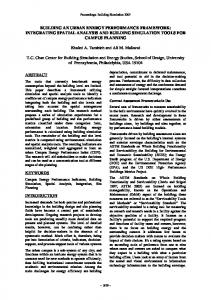
2. Design Objectives of PDELab The advancements in high performance computing technologies have already allowed computational modeling to become a third form of scientific inquiry with the other two being theory and experimentation. It is expected that computational models will impact significantly both “big” and “small” science. In addition, in the near future we will see them used as training simulators of scientific and industrial processes and costly instruments. Their role in education will increase by using them to substitute many of the functions supported by the current wet/dry laboratories. Despite their positive impact and potential, their introduction has significantly increased the complexity of the scientific problem solving process. Figure 1 displays the PDELab view of the modern problem solving process for PDE based applications [6]. It includes pro-
cesses such as brain storming, trial and error reasoning, numeric and experimental data I/O and calibration, numeric and symbolic simulation, advanced reasoning, optimization, visualization and interpretation of results. The main design objective of PDELab is to emulate the above functionality of the problem solving process and automate many of its logical parts. For this we need to integrate numeric, symbolic, geometric, intelligent, and visual computing technologies. PDELab is expected to support users with different computational objectives, background and expertise. This implies that it must be intelligent enough to interpret high level queries whose processing will require support from scientific databases, knowledge bases, and information systems.
Formulate Ideas into Mathematical Representation
Set Up Equations Select Approximations
Describe Variables and Relations
Select Model(s)
Experiment Design
Optimization
Data Acquisition
Evaluate Models
Interpret Results Modify Model(s)
FIGURE 1. The scientific problem solving process for PDE based applications.
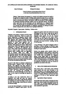
3. Software Architecture of PDELab The software architecture adopted for PDELab is characterized by the software independence of its parts. It is based on the “clean layering” and object-oriented methodologies. At the highest level PDELab consists of three layers. The lowest layer of this model represents the algorithmic and systems infrastructure needed to support the numerical simulation of various “physical” objects on a variety of machines with virtual, generic and specialized architectures. In addition, this layer supports a high level memory system implemented through an object-oriented database system and various domain specific knowledge bases. Figure 2 shows a pictorial view of this architecture. The remainder of this section describes the software
Application PSE Development Framework
PSE Software Infrastructure
Specification Chromatography Tools
Computational Skeletons
Application Workbenches
Custom Chromatography Tools
Knowledge Sources
Visual Programming Tools
Object-Oriented User Interfaces
Programming Environments
Intelligent Multimedia Data Bases
Language Translation Systems
Graphics Display Systems
Machine and System Managers
Software Bus
PSE Algorithms and Systems Infrastructure
Geometric Modeling
Numerical Libraries
Symbolic Systems
Intelligent Parallel Compilers
Memory Management Systems
Expert System Engines
FIGURE 2. The layered software architecture of PDELab.
architecture of each of the layers of PDELab and illustrates it with an application problem solving environment developed with the PDELab framework.
Algorithms and Systems Infrastructure The lowest layer of the PDELab architecture consists of the libraries, knowledge bases and other similar computational agents that drive the simulation process. For PDE computing, these components manipulate a certain collection of meta-objects (consisting of code and knowledge) that are involved in PDE computations, including PDE equations, geometric domains, boundary and initial conditions, grids and meshes of
the PDE geometric regions, matrix equations, and discrete functions. The software architecture of this layer is therefore based on the structure and assumed interactions of these PDE objects. Each module of each library has a certain type signature using these objects. Internal to a module, the data structures and representations can be arbitrary, but that must be packaged into a standard form that uses the PDELab objects before a module can be integrated to PDELab. The PDE objects are designed to be unifying representations of the PDE components; i.e., each object is expected to have sufficient flexibility to represent any instance of that type. This is achieved by following the mathematical behavior in the definitions and by studying the needs of various software packages and then defining the object to satisfy their needs. As software components are implemented in a multitude of languages, representations for the objects are defined in several languages. Currently, C, FORTRAN and Common LISP are supported. Functional representations (in addition to the data structure representation) are also defined when appropriate. As certain objects have multiple “standard” representations, alternate forms and conversions between them are also supported. The representation internal to a module is considered “private,” but if the private representation is common, then a convertor to/from a public form can be registered for it. Convertors can be compiled-in functions or filters applied via pipes.
Software Infrastructure The software infrastructure layer is the “middleware” that facilitates much of the functionality of PDELab. The task of this layer is to facilitate the integration of various software components to form integrated workbenches and also facilitate the development of these components as well. The communication fabric that facilitates component integration is based on the software bus model and is described in detail in Section 4. Other software infrastructure needed to build the upper layer components include graphical display systems and user interfaces as well as object management and database functionality. The PDELab tool development kit, PDEKit, provides this functionality in the form of library utilities that component and custom application tool developers can use.
PSE Development Framework This upper layer of the PDELab architecture provides application PSE developers with a collection of tools and services required to build such PSEs. The tools at this level include visual programming tools that support programming-in-the-large or megaprogramming using PDELab components, computational skeletons for template based programming, tools for editing various PDE objects and support for building custom tools that deal with application dependent aspects of a PSE. These tools are organized into a toolbox available to the application PSE developer and appear as a collection of building tools integrated by
the software bus. The tools themselves are built using the functionality provided by the lower layers and generate some form of configuration scripts. The software architecture of a tool is generally in the form of an event-driven process that is implicitly invoked by the software bus. Section 5 provides an overview of the tools provided by this layer.
Application Problem Solving Environments The architecture of application PSEs developed using the PSE development framework views a PSE as a collection of distributed tools that collaborate with each other to solve some problem. This architecture is supported by the same software bus methodology and the collection of objects representing various PDE components that drives the PSE development framework. However, at the end-user level, the PSE developed using PDELab appears as a centralized system with the custom user-interface controlling all the components executing underneath. The custom interface communicates with the user in application domain terms (and not in mathematical PDE terms) by translating domain terminology to/from the appropriate mathematical representations.
4. The PDELab Software Bus The underlying communication fabric for PDELab is based on the software bus [10] model. The software bus concept is an attempt to emulate the hardware bus mechanism that provides a standard hardware interface to attach additional capabilities to a machine. In the hardware bus, new units describe their capabilities to the bus controller, which then passes the information along to other units in the bus. In the PDELab software bus, PDEBus, software components register their “exported” services with the software bus and rely on the software bus to invoke these services when requested by interested clients. The software bus is responsible for the application of any representation translators as required for the valid invocation of the service. Thus, the software bus provides a mechanism where two tools can interoperate with each other without having explicit knowledge about each other and also provides the infrastructure for managing a set of distributed tools.
4.1 Requirements: Clients, Protocols and Services The requirements of the PDELab communication system can be stated in terms of three parameters: The types of clients it needs to service, the client communication protocols it supports, and the services provided to clients.
In the PDELab context, there are many types of clients (in terms of their execution nature) that must be supported. These include reactive (or event-driven) clients that register services that they provide and then asynchronously receive requests and service them. An example of this is a client that provides a simple differentiation service. Another type of client is a command-driven client; given some command, it responds with an “answer.” Other clients are off-line clients which require no input, but some other client may be interested in its output. The software bus must provide tools and mechanisms to interact with all these types of clients as often we (as the developer of a problem solving environment) do not have the option of adapting them to any preferred interaction model. PDEBus must support protocols for at least three different client interactions: the software bus’ own client interaction protocol (for clients built with the software bus client library), raw byte-streams (for arbitrary communication) and a line-oriented protocol (for interacting with command-oriented clients). The services provided by PDEBus to clients can be categorized into three groups: location services, process management services and messaging services. For client/object location purposes, a global naming scheme based on uniform resource locators (URLs) [1], a highly flexible emerging standard for naming arbitrary resources, is being developed. The software bus will provide various directory services with URLs being the naming standard. The process management facilities provided by PDEBus include facilities to invoke and control both local and remote processes and facilities to set up pre-wired configurations of clients and facilities. PDEBus’ messaging services range from low-level byte stream messages to communicating arbitrary data structures via self-describing or network-transparent representations to remote procedure calls.
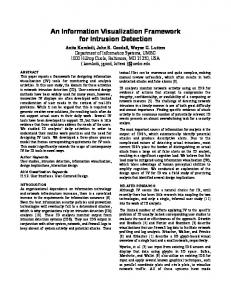
4.2 Bus Architecture The PDEBus architecture reflects the problem solving environment architectural model described earlier. Clients are built using the PDEBus client library and, at run-time, connect to a “manager” process. A manager process exists for each user, application and machine (an “access domain”) and serves as the clearinghouse of inter-client messages and client requests. While inter-client messages travel via the manager by default, it is possible to establish direct, point-to-point links when necessary. The manager processes themselves are connected to each other via multiple I/O channels. Interprocess communication occurs via TCP/ IP sockets, pipes, shared memory or pseudo-terminals, depending on what the two components can support. In order to avoid being a bottleneck, the manager process generally uses shared memory to communicate with its clients and is multithreaded. Figure 3 shows a schematic of this architecture.
SB SB
SB
Key SB
PDEBus Manager Process Client Access Domain
FIGURE 3. A view of the PDEBus architecture.
The PDEBus implementation respects all the standard access controls supported by the underlying operating environment and guarantees security. This is affected by following the usual mechanisms for getting access to a machine (to run a manager process) and by using a Kerberos-like security mechanism for authenticating and validating clients once a manager process is active. Communication of arbitrary data types is supported in two ways. First, a self-describing data format can be used to inform the underlying communication medium of the types of data being communicated. Second, PDEBus allows clients to register their own convertors to/from the data structure and the transport representation. Using this latter mechanism, one can transmit and receive data in the eXternal Data Representation (XDR), The software architecture of PDEBus is a layered architecture with the lowest level providing a packet-based messaging system implemented over a reliable byte-stream protocol such as TCP/IP. The next layer provides support for messaging and arbitrary data type communication. The highest layer provides remote procedure calls and event-driven messaging.
4.3 Configuring a New PSE Building an application problem solving environment requires one to develop application specific modules and then interconnect those modules with a subset of PDELab tools. Since inter-component communication is transparently achieved via URLs and PDEBus’ messaging system, one only needs to have PDEBus initiate and manage those components. This is achieved via the session initiation script mechanism of PDEBus. This script (implemented using Tcl [9]) instructs PDEBus to initiate the components required for
the session. Graphical development tools at the upper layer of PDELab assist in developing these session initialization scripts.
5. PSE Development Framework The highest layer of the PDELab environment is the problem solving environment development framework. At this level, application PSE developers compose new PSEs by combining together components from PDELab and the application specific components they implement using PDELab provided development tools. This framework consists of several subsystems: PDE object editing tools, a graphical worksheet editor, the PDESpec language and associated tools, the PYTHIA [5] reasoning environment, the composer, and of course the developer’s kit described earlier. We discuss the object editing tools, the worksheet editor, PDESpec, PYTHIA and the composer here.
PDE Object Editors. The PDEView object editing environment consists of a collection of tools that allow users to create, edit and manipulate PDE objects. For example, PDEView includes tools for editing domains, equations, boundary and initial conditions, generating meshes and visualizing data. The two-dimensional domain editor, for example, allows users to define a domain by specifying the boundary (graphically and/or textually) and any holes. The resulting domain object can be transmitted to another editor (to the mesh editor for meshing, for example) or can be saved in a file or in a session editor. Several of PDEView’s object editors are frameworks for integrating specific functionality relevant to the tasks supported by the editor. That is, an editor is not merely a user interface supporting certain built-in, fixed functionality. Instead, the editors support a process whereby libraries and systems that perform related operations can be installed in the editor. Thus, foreign systems and libraries can be integrated to PDELab with little effort and foreign software can take advantage of the complex PDE machinery built into the PDELab environment. As an example, let us consider the two-dimensional mesh editor. The 2D mesh editor requires a 2D domain object as input and produces a mesh object as output. Given the vast array of 2D mesh generators that are available, it would be restrictive indeed to build in a fixed library of mesh generators. Instead, the mesh editor provides some basic functionality which includes loading in and displaying 2D domains of various formats, displaying and saving 2D meshes in various formats and converting meshes from one format to another. The actual mesh generation capabilities are “loaded in” to the mesh editor via Tcl scripts. A mesh generator installer uses the embedded script language to instruct
FIGURE 4. Examples of graphical editors from PDELab.
the mesh editor where the mesh library is, what top-level function to call, what the user-specifiable parameters are and what data the mesh generator produces. Format conversions can also be specified in this script. Adaptive mesh generators requiring multiple calls to the generators are also supported. Figure 4 shows instances of the PDELab 2D mesh editor, visualization controller, the 2D mesh visualizer and the worksheet editor described below.
Worksheet Editor. Application PSEs can use the graphical worksheet editor as the central access point for the PSE or as a session log containing all the objects created during the session. This editor provides standard editing capabilities (delete, cut, paste, etc.) and also allows users to convert between the text and data structure representations of objects.
PDESpec Language. The PDESpec language is PDE specification language that allows the user to specify the PDE problem using textbook type notation and to direct the PDE solution using a high level pseudo-code to combine existing computational modules or PDE parts in a serial or nested form. The language is also defined in
terms of the PDE objects and the language form of an object is generally viewed as an alternate representation format for objects. PDESpec supports both a compile-execute model and an interpreted execution model and is defined as an extension of the MACSYMA [7] language. The MACSYMA parser is used to parse a PDESpec program and the compiler (implemented in MACSYMA, Common LISP and C) generates a program in FORTRAN using the GENCRAY [13] code generation package. For interpreted programs, a parsed version of the program is handed over to the PDESpec interpreter for execution. By implementing the language as an extension of the MACSYMA computer algebra system’s language, PDELab supports direct symbolic transformations at the language level.
PYTHIA Environment. In a problem solving environment, there are many situations where intelligent reasoning rather than algorithmic logic in necessary. For example, when selecting a solution scheme to solve a given PDE problem, it is necessary to apply various rules of thumb, heuristics and experience rather than a simple formula. PYTHIA supports this type of “soft” reasoning by providing an environment where one can integrate rule and knowledge bases and associated reasoning systems. PYTHIA is accessed as a tool in the PDELab environment and is implemented with an embedded version of CLIPS [3].
Component Composition. A major step in building an application PSE with PDELab is combining a set of components together into a PSE using PDEBus. The composition editor supports this activity by providing a graphical environment for selecting components (editors) and “wiring” them together appropriately. The resulting data flow graph is transformed into PDEBus scripts that can be used to represent the composed application PSE.
6. BioSoftLab: The Bioseparation Workbench A major objective of PDELab is to provide a methodology for building application-specific problem solving environments. This methodology allows users with very specialized requirements to wire together components of PDELab to create an environment exactly suited to the solution of the PDEs that model their scientific application. The Bioseparation Workbench, referred to throughout as BioSoftLab, is a prototype of such a specialized environment which is currently being developed using PDELab. Bioseparation is a process for separating components by passing a solution mixture through an absorbent column, so that each component adsorbs to the surface differently from the others, and thus eludes at difference times [2]. This process is used in the purification of proteins and biochemicals, in the manufacture of pharmaceutical
products, in water treatment, and in many other bio-chemical processes. The process is modelled by a system of 1D and 2D nonlinear, time-dependent PDEs. BiosSoftLab models the bioseparation process, and its target users are chemical engineers who perform bioseparation experiments and who run numerical simulations of the bioseparation process using customized code. The Bioseparation Workbench provides a powerful and flexible environment for simulating the experiment numerically, using all the editors, techniques and solvers from PDELab that are appropriate to the model for this process. This workbench supports the specification, solution, and analysis of the bioseparation model using many different schemes, including the original customized code. The PDELab methodology was first used to integrate the original solution method into BioSoftLab, so that the engineers could continue to simulate the process as they have done in the past. PDEKit development tools were used to build a template for entering numerical input data specific to their customized solver. The template is an abstraction of the PDE model, and communicates in terminology that is familiar to the engineer. The original solution software was integrated into the PDEPack library of solvers, and is now accessed through the BioSoftLab interface. Simulation results are generated in various formats, and PDELab visualization tools are used for viewing time slices, data slices or animations of the results. This procedure for solving the bioseparation problem used the PDELab template builder, PDEPack solver integration techniques, and the PDELab visualization tools. The engineers have gained a graphical interface for problem specification and solution, and visualization tools for viewing and analyzing the simulation results. However, a much broader implementation of PDELab functionality within BioSoftLab is planned. Since PDELab provides numerous tools and methods for defining and solving PDE problems, it is natural to investigate other solution schemes for the bioseparation process. Instead of specifying the model via a set of customized parameters, PDELab editors can be used to specify the mathematical model in terms of objects such as equations, domains, boundary conditions and initial conditions. Algorithm objects in conjunction with existing PDEPack solvers can be used to solve the model via many different solution paths. More accurate, more flexible or more efficient methods for solving this model may be found using alternate problem solving procedures available through the Bioseparation Workbench. Prototypes for the required PDELab editors already exist, and the editors will be configured together for BioSoftLab using PDEBus.
7. References [1] T. Berners-Lee, “Uniform Resource Locators: A unifying syntax for the expression of names and addresses of objects on the network,” (Draft) Internet RFC, 1993, . [2] J. A. Berninger, R. D. Whitley, X. Zhang, N.-H. L. Wang, “A Verstile Model for Simulation of Reaction and Nonequilibrium Dynamics in Multicomponent Fixed-Bed Adsorption Processes,” Computers in Chemical Engineering, 15(11), 1991, pp. 749-768. [3] J. C. Giarratano, “CLIPS User’s Guide, Version 5.1,” NASA Lyndon B. Johnson Space Center, 1991. [4] D. E. Hall, W. H. Greiman, W. F. Johnston, A. X. Merola, S. C. Loken and D. W. Robertson, “The Software Bus: A Vision for Scientific Software Development,” Computer Physics Communications, 57, 1989, pp. 211-216. [5] E. N. Houstis, J. R. Rice, S. Weerawarana and C. E. Houstis, “PYTHIA: A Computationally Intelligent Paradigm to Support Smart Problem Solving Environments for PDE Based Applications,” to appear, 1994. [6] G. J. MacRae, “Role of High Performance Computing in Environmental Modeling,” Proceedings of Very Large Scale Computations in the 21st Century, SIAM, 1991, pp. 41-72. [7] Macsyma Reference Manual, Version Nine, The MATHLAB Group, Laboratory for Computer Science, Massachusetts Institute of Technology, 1977. [8] H. S. McFaddin, “An Object-based Problem Solving Environment for Collaborating PDE Solvers and Editors,” PhD Thesis, Department of Computer Sciences, Purdue University, 1992. [9] J. Ousterhout, “Tcl: An Embeddable Command Language,” Proc. USENIX Winter Conference, January 1990, pp. 133-146. [10] J. Purtilo, R. T. Snodgrass and A. L. Wolf, “Software Bus Organization: Reference Model and Comparison of Two Existing Systems,” ARPA Module Interconnection Formalism Working Group, TR-8, 1991, . [11] J. M. Purtilo, “The Polylith Software Bus,” ACM Transactions on Programming Languages and Systems, 16(1), 1994, pp. 151-174. [12] K. Sayre and M. A. Gray, “Backtalk: A Generalized Dynamic Communication System for DAI,” Software-Practice and Experience, 23(9), 1993, pp. 1043-1057. [13] S. Weerawarana and P. S. Wang, “A Portable Code Generator for CRAY FORTRAN,” ACM Transactions on Mathematical Software, 18(3), 1992, pp. 241-255.